Table of Contents
Advertisement
Quick Links
Quick Start Installation
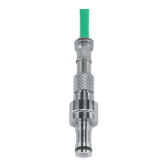
4 mm Cavity Pressure and Temperature Sensor
Type 6190CA... (–9 pC/bar, 2 000 bar, 200 °C)
(Thermocouple Type K)
Content
Front Page: Machining the Mold
1.
General Notes
2.
Important Areas of Sensor Hole
3.
Hole
3.1 Unmachined Sensor
3.2 Cavity-Matched Sensor
4.
Cable Channeling and Connector
4.1 Single-Wire Cable Technology
Rear Page: Sensor Installation, Service and Repair
5.
Installing Sensor
6.
Installing Cable and Connector
6.1 Single-Wire Technology
7.
Installing Identification Plate
8.
Functional Test
9.
Service and Repair
Foreword
Information in this document is subject to change without
notice. Kistler reserves the right to change or improve its
products and make changes in the content without obliga-
tion to notify any person or organization of such changes or
improvements.
© 2008, Kistler Group. All rights reserved.
1. General Notes
•
Sensor ø4 mm may not be machined
•
Front of sensor must be clean and without notches
•
Only use recommended installation accessories
•
Do not use cable to pull sensor out of hole
2. Important Areas of Sensor Hole
Be aware of the following important areas of the bore:
1. Sensor contact surface must be flat and perpendicular
2. H7 hole to center sensor
3. Chamfer protects O-ring during installation
4. Not to be used to center sensor
5. Sharp edges reduce witness mark on part
3. Hole
3.1 Unmachined Sensor
For use in flat cavity wall with sensor fitted at right angles
to cavity
•
Hole and thread must be free of debris and shavings
•
Accessories set Type 1300A81 may be used
3.1.1 Sensor with Mounting Nut Type 6457
Electrical discharge machine (EDM), mill or precision grind H7
hole in hardened tool steel. Check centering and alignment.
Clean thread of debris and shavings.
6190C_002-433e-08.08
3.1.2 Sensor with Spacer Sleeve Type 6459
EDM, mill or precision grind H7 hole in hardened tool steel.
Check centering and alignment. Clean thread of debris and
shavings.
3.2 Hole for Cavity-Wall Matched Sensor
This sensor has a thermocouple welded into the front face.
The sensor cannot be machined to match the cavity wall.
•
Sensor CANNOT be machined
4. Cable Channeling and Connector
•
Install cables in channels to simplify mould assembly
•
Do not route cables next to hot runner cartridge
•
Chamfer all sharp edges
•
Cover open channels/slots
4.1 Single-Wire Technique
The single-wire technique uses the tool steel of which the mould
is made to ensure an electrical shielding of the sensor signal.
Thus the wiring can be run through drilled holes or channels.
•
Single-wire cable must be completely enclosed in
the mold
•
Single-wire cable may not be run together with
power cables
4.1.1 Single-wire Connector Type 1839 and Temperature Con-
nector
A sensor supplied with assembled connectors is run in a chan-
nel with a recess for mounting plate.
•
Ensure radii are machined in channels
•
Cover open channels to prevent cable damage
4.1.2 Multi-channel Single-Wire Connectors and Tempe ra-
ture Amplifier
Sensors Type 6190CAG/G1 or sensors in the set Type
6833A..., which are all connected to 4-channel connector
Type 1708A... and temperature amplifier Type 2205A...,
require the following channels and recess.
Recess for 4-channel connector Type 1708A..., temperature
amplifier Type 2205A... and adapter plate Type 5700A25
Advertisement
Table of Contents

Related Manuals for Kistler 6190CA Series


Summary of Contents for Kistler 6190CA Series
- Page 1 3.2 Hole for Cavity-Wall Matched Sensor Information in this document is subject to change without notice. Kistler reserves the right to change or improve its This sensor has a thermocouple welded into the front face. products and make changes in the content without obliga- The sensor cannot be machined to match the cavity wall.
- Page 2 Damaged cables cannot be repaired. Replacement cable Type 2219B... can be ordered from Kistler local sales office. • Fragile contacts, remove cable only for repair 9.5 Repairs at Kistler Factory repairs at Kistler are arranged by the local sales office • Do not preload sensor Information: www.kistler.com •...
Need help?
Do you have a question about the 6190CA Series and is the answer not in the manual?
Questions and answers