
Related Manuals for Onicon SYSTEM-1000


Summary of Contents for Onicon SYSTEM-1000
- Page 1 SYSTEM-1000 SYSTEM-1000 FLOW AND ENERGY MEASUREMENT SYSTEM FLOW AND ENERGY MEASUREMENT SYSTEM Installation and Operation Guide Installation and Operation Guide ONICON DOC-0005327 Rev.A...
-
Page 2: Heavy Duty Thermowell Assembly For Process Temperatures Over 300°F
SYSTEM - 1000 FLOW AND ENERGY MEASUREMENT SYSTEM SAFETY INFORMATION The System-1000 BTU Meter was calibrated at the factory before shipment. To ensure correct use of the system, please read this manual thoroughly. Regarding this manual: • This manual should be passed on to the end user. -
Page 3: Table Of Contents
SECTION 2.0 UNPACKING ............................8 2.1 CHECKING THAT YOU HAVE RECEIVED EVERYTHING ....................8 SECTION 3.0 INSTALLATION............................ 9 3.1 SITE SELECTION ....................................9 3.1.1 The System-1000 BTU Meter ............................9 3.1.2 The Flow Meter ..................................9 3.1.3 The Temperature Sensors ..............................9 3.2 MECHANICAL INSTALLATION ..............................10 3.2.1 Thermowell Installation ..............................11... -
Page 4: Section 1.0 General Information
SECTION 1.0 GENERAL INFORMATION We at ONICON Incorporated would like to thank you for purchasing our quality American made System-1000 BTU Meter. As our valued customer, our commitment to you is to provide fast reliable service, while continuing to offer quality products to meet your growing flow measurement needs. -
Page 5: Standard Features And Specifications
Eight (8) Active Analog Outputs Analog Outputs Eight (8) Isolated Dry Contact Inputs for Digital Outputs Totalization or Alarm * SPECIFICATIONS subject to change without notice. Note - See model codification for additional information regarding option selections. ONICON Incorporated 727.447.6140 Page 5 onicon.com... -
Page 6: Model Numbering System
* SPECIFICATIONS subject to change without notice. ** The default address is set to slave to prevent bus contention. The user will have to program the master address they desire for MS/TP communication with the SYSTEM-1000 to proceed. 1.4 MODEL NUMBERING SYSTEM... -
Page 7: Additional Required Hardware
F-5400/F-5500 Thermal Mass Flow Meters ¾” - 24” Inline/Insertion Please refer to ONICON’s flow meter IOM, or contact ONICON for help in selecting the flow meter that will best fit your requirements. 1.6 WORKING ENVIRONMENT The System-1000 was designed for installation and use in typical industrial environments that are free of corrosive liquids and fumes, direct liquid exposure, temperature extremes and vibrations. -
Page 8: Section 2.0 Unpacking
ONICON customer service department. Most products are shipped insured unless the customer speci cally requests otherwise. CHECK THAT YOU HAVE RECEIVED EVERYTHING Each box comes with a label identifying the ONICON job number, Model Number, Serial Number, and Tag Information. (Use tags to identify the meter location.) Typical order includes:... -
Page 9: Section 3.0 Installation
If the System-1000 is configured as a dual-channel system, it can be paired with two sets of temp sensors for two independent energy measurements. -
Page 10: Mechanical Installation
(4) DRYWALL ANCHORS THAT SUPPORT A MINIMUM OF 60 LBS CENTERLINE USE FOR LEVELING Image not to scale ONICON Incorporated • www.onicon.com • sales@onicon.com • +1 (727) 447-6140 CAUTION DO NOT drill holes in the enclosure. Use only the openings that are provided. ONICON Incorporated 727.447.6140 Page 10 onicon.com... -
Page 11: Thermowell Installation
SYSTEM - 1000 FLOW AND ENERGY MEASUREMENT SYSTEM 3.2.1 Thermowell Installation Sections 3.2.1.1 - 3.2.1.3 are thermowell kits for ONICON solid state temperature sensors and high temperature RTDs with matching transmitters. See sections 3.2.1.4 - 3.2.1.5 for thermowells for 4-wire RTDs... - Page 12 DO NOT OVER TIGHTEN THE POSITION CLAMPING NUT. If fluid leaks, do not attempt to correct by tightening this nut further. An internal o-ring seals the fluid. Contact ONICON for assistance in the event of a leak. ONICON Incorporated 727.447.6140 Page 12 onicon.com...
-
Page 13: Clamp-On Thermowell (Onicon/Analog)
Clamp-on thermowells are for metallic pipes ONLY and are typically used along with clamp-on ultrasonic flow meters. It is also very important to properly insulate over them. The insulation thickness (or R value) required is proportional to the difference between ambient temp and process temp. ONICON Incorporated 727.447.6140 Page 13 onicon.com... -
Page 14: 5Mm Diameter Thermowell (4-Wire Rtds)
1. RTD temperature sensor – provided by ONICON. 2. 5 mm diameter thermowell – provided by ONICON. 3. 1” solder x ½” NPT bushing OR line size x ½” bushing – provided by customer or ordered from ONICON. 4. Customer supplied line size tee. -
Page 15: Temperature Sensor Installation
One temperature sensor can be installed five diameters downstream of the flow meter leaving enough clearance to remove either sensor from the pipe without interference from the other sensor. Refer to the flow meter IOM and/or other documentation that is provided with your ONICON flow meter. ONICON Incorporated 727.447.6140 Page 15 onicon.com... -
Page 16: Electrical Installation
• 99-253 VAC, 50/60 Hz, 100VA IMPORTANT NOTE: This option is not field selectable. Contact ONICON prior to installation if needed to change the input voltage rating. WARNING Conduit openings in the System-1000 enclosure must be closed with UL listed fittings applicable to NEMA 13 enclosures. -
Page 17: Input Signal Connections
SYSTEM - 1000 FLOW AND ENERGY MEASUREMENT SYSTEM 3.3.2 Input Signal Connections ONICON Incorporated 727.447.6140 Page 17 onicon.com... -
Page 18: Input Signal Connections From Flow Meters
SYSTEM - 1000 FLOW AND ENERGY MEASUREMENT SYSTEM 3.3.2.1 Input Signal Connections From Flow Meters ONICON Incorporated 727.447.6140 Page 18 onicon.com... -
Page 19: Temperature Input Wiring Details
SYSTEM - 1000 FLOW AND ENERGY MEASUREMENT SYSTEM 3.3.2.2 Temperature Input Wiring Details ONICON FIXED RANGE or LOOP POWERED 4-20mA SCALABLE RANGE TEMPERATURE INPUTS TERMINAL BLOCK TB5 (+) Signal 1. (+) SUPPLY TEMP Supply Temperature Sensor (-) Reference 2. (-) SUPPLY TEMP Shield 3. -
Page 20: Input Signal Connections For Temperature Sensors
3.3.2.3 Input Signal Connections for Temperature Sensors Do not exceed 4.5 in-lb (0.5 Nm) of torque when tightening. CAUTION Shield connections are required for proper operation. Failure to use shielded cable may result in erratic operation. ONICON Incorporated 727.447.6140 Page 20 onicon.com... -
Page 21: Peripheral Devices: Flow Meters
SYSTEM - 1000 FLOW AND ENERGY MEASUREMENT SYSTEM 3.3.2.4 Peripheral Devices: Flow Meters ONICON flow meters are provided with a number of different output configurations. These affect the number of wires contained in the cable attached to the flow meter. Refer to the diagram below meter. -
Page 22: Output Signal Connections
OUTPUT 2 OUTPUT 3 COMM COMM J11-15 J11-13 J11-11 J12-3 J8-13 J8-15 J8-17 J12-5 PULSE OUT (+) PULSE OUT (+) PULSE OUT (-) J11-16 J11-14 J11-12 J12-2 J8-14 J8-16 J8-18 J12-4 PULSE OUT (-) ONICON Incorporated 727.447.6140 Page 22 onicon.com... -
Page 23: Section 4.0 Start - Up And Commissioning
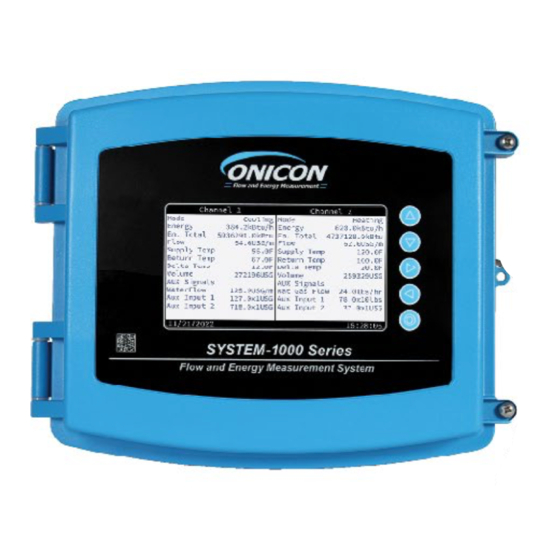
SECTION 4.0 START - UP AND COMMISSIONING 4.1 DISPLAY AND USER INTERFACE When power is applied to the System-1000, the Main Menu screen will appear on the display. Five (5) button user interface is provided to operate and program the meter. -
Page 24: Commissioning
SYSTEM - 1000 FLOW AND ENERGY MEASUREMENT SYSTEM 4.3 COMMISSIONING Upon initial installation, it is strongly recommended that the SYSTEM-1000 and its associated flow meters are commissioned to ensure that they are properly installed and functioning correctly. This process involves verifying the mechanical installation, measuring flow and temperature signals and then comparing these measurements to the specified installation and operating parameters listed on the FACTORY CONFIGURATION SHEET provided with the meter. - Page 25 SYSTEM - 1000 FLOW AND ENERGY MEASUREMENT SYSTEM ONICON Incorporated 727.447.6140 Page 25 onicon.com...
-
Page 26: Network Configuration
Shield wires must not be connected to the RS485 connector on the System-1000 • The maximum number of devices allowed on an RS485 network segment without a repeater is 32. - Page 27 • If the meter is connected to an active network, • If the meter is connected to an active network, System-1000 display will show Active on the NETWORK System-1000 display will show Active on the NETWORK message message Link Down: No traffic has been seen in 60 seconds 2.
- Page 28 SYSTEM - 1000 FLOW AND ENERGY MEASUREMENT SYSTEM BACnet Protocol Implementation Conformance Statement Date: 01/03/2023 Vendor Name: ONICON Inc. Product Name: System 1000 Product Model Number: SYS-1100-111, SYS-1100-121, SYS-1200-111, SYS-1200-121 Application Software Version: 1.26.1 Firmware Revision: 1.3.0 BACnet Protocol Revision: 16 BACnet Standardized Device Profiles Supported (Annex L): ...
- Page 29 Indicating support for multiple character sets does not imply that they can all be supported simultaneously. ISO 10646 (UTF-8) IBM™/Microsoft™ DBCS ISO 8859-1 ISO 10646 (UCS-2) ISO 10646 (UCS-4) JIS X 0208 ONICON Incorporated 727.447.6140 Page 29 onicon.com...
- Page 30 Present Secondary Rate for Channel 2 (if used) Present COP. Depends on an electric meter input from AUX AI 15 Efficiency COP Ch. 2 Input Channel 1 AI16 Therm Energy Net Rate Ch1-Ch2 Thermal Differential between both channels (if used) ONICON Incorporated 727.447.6140 Page 30 onicon.com...
- Page 31 Non-resettable Reverse or dual mode volume total Channel 2 AV 29 Volume Total Mode 2 Ch. 2 (Heating when it is dual mode settings) AV 30 YTD Vol Total Mode 1 Ch. 2 Year-to-date unidirectional volume total Channel 2 ONICON Incorporated 727.447.6140 Page 31 onicon.com...
- Page 32 Aux Pulse Input PrevYr Total 4 Previous year's aux 4 pulse totalization Channel 1 AV 55 Aux Pulse Input User Total 4 Resettable aux 4 pulse totalization Channel 1 AV 56 Run hours Elapsed system runtime in hours ONICON Incorporated 727.447.6140 Page 32 onicon.com...
- Page 33 State of the alarm if digital in 3 is configured for alarm input. BI 7 Aux In Alarm 4 State of the alarm if digital in 4 is configured for alarm input. BI 9 System Fault System error ONICON Incorporated 727.447.6140 Page 33 onicon.com...
-
Page 34: Section 5.0 Menu Tree
SYSTEM - 1000 FLOW AND ENERGY MEASUREMENT SYSTEM SECTION 5.0 MENU TREE The real time data is found in the Energy Measurements Menu. ONICON Incorporated 727.447.6140 Page 34 onicon.com... - Page 35 SYSTEM - 1000 FLOW AND ENERGY MEASUREMENT SYSTEM ONICON Incorporated 727.447.6140 Page 35 onicon.com...
- Page 36 Aux Digital Outputs: The SYS-1000 can be factory configured with QTY (4) or QTY (8) digital outputs. Each digital output can be field configured for a variety of energy and flow readings. Multiplier options: 1, 10, 100, 1K, 10K, 100K, 1MEG ONICON Incorporated 727.447.6140 Page 36 onicon.com...
- Page 37 SYSTEM - 1000 FLOW AND ENERGY MEASUREMENT SYSTEM Please refer to Section 4.5 Network and Configuration ONICON Incorporated 727.447.6140 Page 37 onicon.com...
- Page 38 SYSTEM - 1000 FLOW AND ENERGY MEASUREMENT SYSTEM ONICON Incorporated 727.447.6140 Page 38 onicon.com...
- Page 39 SYSTEM - 1000 FLOW AND ENERGY MEASUREMENT SYSTEM ONICON Incorporated 727.447.6140 Page 39 onicon.com...
-
Page 40: Section 6.0 Diagnostics
Active: communication board is connected to the main board. Not connected: Main board is unable to communicate with the communications board. Contact ONICON if the communications board is damaged or unresponsive. Network: Provides information about the communication with the network. -
Page 41: Alarm Messages
Verify all configured parameters Flowmeter configured parameters are METER CONFIGURATION CORRUPT match the configuration on your not valid. ONICON calibration certificates The flow reading is below the Increase flow through the pipe. minimum flow threshold of ALARM LOW FLOW Increase configured full scale of the the meter (e.g. - Page 42 TEMP_HIGH (see above) input terminals. Replace internal battery. The main Warning that the internal battery has board must be removed to access WARN RTC FAIL failed. the battery. Contact ONICON for assistance in correcting this. ONICON Incorporated 727.447.6140 Page 42 onicon.com...
- Page 43 Contact ONICON for assistance in correcting this condition. To clear this alarm message, first...
-
Page 44: Appendix A - Drawings
SYSTEM - 1000 FLOW AND ENERGY MEASUREMENT SYSTEM APPENDIX A – DRAWINGS OUTDOOR THERMOWELL ASSEMBLY A-2 & A-3 HEAVY DUTY THERMOWELL FOR HIGH TEMPERATURE / PRESSURE (2 Pages) ONICON Incorporated 727.447.6140 Page 44 onicon.com... -
Page 45: Outdoor Thermowell Assembly In Welded Pipe
APPENDIX OUTDOOR THERMOWELL ASSEMBLY IN WELDED PIPE ONICON Incorporated 727.447.6140 A - 1 onicon.com... - Page 46 The thermowell, extension nipple, coupling and fitting were made to a specific length. DO NOT attempt to change the length of this assembly. Step 1: Drill 7/8” hole in pipe. Install thermowell using fittings supplied by ONICON. Complete steps 2 - 4 only after all welding, brazing & soldering are complete. IMPORTANT NOTE Each RTD and transmitter pair are matched at the factory and calibrated for a specific BTU meter.
- Page 47 In 1” pipe, thermowell must be installed in a customer provided tee as shown below. The thermowell, extension nipple, coupling and fitting were made to a specific length. DO NOT attempt to change the length of this assembly. ONICON Incorporated 727.447.6140 A - 3 onicon.com...
- Page 48 ONICON ONICON Incorporated • 11451 Belcher Road South • Largo, FL 33773 • USA 727.447.6140 • sales@onicon.com • onicon.com...
Need help?
Do you have a question about the SYSTEM-1000 and is the answer not in the manual?
Questions and answers