Onicon SYSTEM-30 BTU Installation And Operation Manual
Hide thumbs
Also See for SYSTEM-30 BTU:
- Installation and operation manual (32 pages) ,
- Installation and operation manual (38 pages)
Table of Contents
Advertisement
Quick Links
SYSTEM-30 BTU MEASUREMENT SYSTEM
LON Version
Installation and Operation Guide
For Software Version 2.8B Higher
1500 North Belcher Road, Clearwater, Florida 33765 (727) 447-6140 Fax (727) 442-5699
www.onicon.com E-mail: sales@onicon.com
System-30 BTU Measurement System LON – Installation Guide – Revised 10/2006
1
Advertisement
Table of Contents

Subscribe to Our Youtube Channel
Related Manuals for Onicon SYSTEM-30 BTU


Summary of Contents for Onicon SYSTEM-30 BTU
- Page 1 SYSTEM-30 BTU MEASUREMENT SYSTEM LON Version Installation and Operation Guide For Software Version 2.8B Higher 1500 North Belcher Road, Clearwater, Florida 33765 (727) 447-6140 Fax (727) 442-5699 www.onicon.com E-mail: sales@onicon.com System-30 BTU Measurement System LON – Installation Guide – Revised 10/2006...
- Page 2 ONICON assumes no responsibilities for this product except as stated in the warranty. • If the customer or any third party is harmed by the use of this product, ONICON assumes no responsibility for any such harm owing to any defects in the product which were not predictable, or for any indirect damages.
-
Page 3: Table Of Contents
4.5.3 Node Object Network Variables ..............22 4.5.4 Sample System-30-LON Set Up Document ..........23 4.6 Diagnostics ........................27 4.6.1 Diagnostic Lights..................27 4.7 Commissioning ......................28 4.7.1 Commissioning Worksheet ...............29 TROUBLESHOOTING GUIDE ......................29 System-30 BTU Measurement System LON – Installation Guide – Revised 10/2006... - Page 4 APPENDIX A – DRAWINGS TYPICAL SYSTEM INSTALLATION A-2 / A-3 THERMOWELL INSTALLATION WIRING DIAGRAM SIGNAL CONNECTION BOARD WIRING DIAGRAM FOR DIN CONNECTOR System-30 BTU Measurement System LON – Installation Guide – Revised 10/2006...
-
Page 5: Introduction
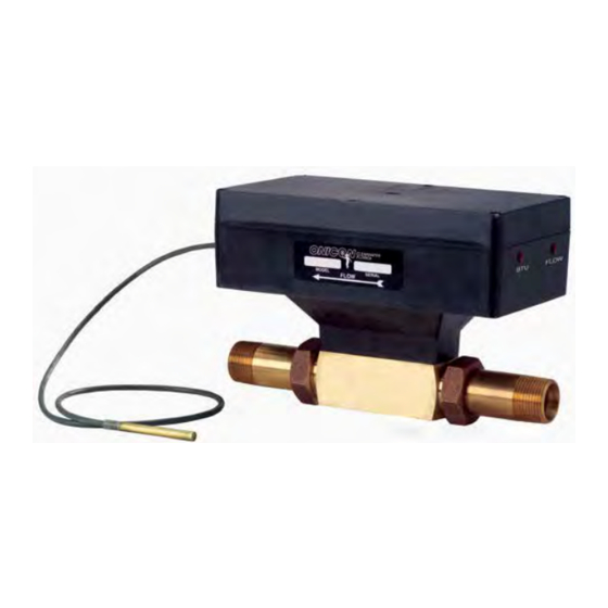
SYSTEM. TYPICAL SYSTEM-30 BTU MEASUREMENT SYSTEM ONICON’S System-30 is a true heat (BTU) computer, which accepts data from several sensors, performs a series of computations with that data, and transmits the results as an indication of the amount of heat (BTU’s) being transferred or as a totalized amount. -
Page 6: Standard Features And Specifications
Alphanumeric LCD displays total energy, total Note: Specifications are subject to change without Flow, energy rate, flow rate, supply temperature notice. and Return temperature Alpha: 16 characters, 0.2” high Numeric: 6 digit, 0.4” high System-30 BTU Measurement System LON – Installation Guide – Revised 10/2006... -
Page 7: Working Environment
The serial number of your SYSTEM-30 is located on the side of the enclosure. Serial numbers are unique identifiers that you should have available when contacting the factory for assistance regarding your system. System-30 BTU Measurement System LON – Installation Guide – Revised 10/2006... -
Page 8: Unpacking
A compression fitting with retaining nut makes up one end of each tail piece. The other end will either be a sweat fitting for copper or a threaded nipple with NPT threads. System-30 BTU Measurement System LON – Installation Guide – Revised 10/2006... -
Page 9: Installation
ONICON will be happy to assist with technical recommendations and to provide guidance by telephone and/or mail. On-site field engineering, installation, and/or service is also available at an additional cost. -
Page 10: Mechanical Installation
Before you attempt to use the BTU MEASUREMENT SYSTEM, isolate the main unit, open the bypass and flush the entire system so that it is free of flux, solder, pipe and tube cuttings and any other free moving particles. System-30 BTU Measurement System LON – Installation Guide – Revised 10/2006... -
Page 11: Thermowell Installation
Cable length is specified at time of order. This is three wire shielded plenum rated cable. Altering the cable length may affect calibration. Do not change the cable length without consulting ONICON. System-30 BTU Measurement System LON – Installation Guide – Revised 10/2006... - Page 12 THERMOWELL INSTALLATION IN THREADED PIPE TEES THERMOWELL INSTALLATION IN COPPER TEE System-30 BTU Measurement System LON – Installation Guide – Revised 10/2006...
- Page 13 THERMOWELL INSTALLATION IN WELDED PIPE System-30 BTU Measurement System LON – Installation Guide – Revised 10/2006...
-
Page 14: Electrical Installation
SINGLE MODE (4 PIPE) vs. DUAL MODE (2 PIPE) OPERATION ONICON System 30 BTU meters may be configured for single or dual mode applications. Single and dual mode is a reference to the piping system and not the meter itself. Single mode (4 pipes) applications are those that always have the same relationship between the supply and return pipe temperatures. - Page 15 Temperature 1 Sensor (Internal Sensor) Return Temp Temperature 2 Sensor (External Sensor) Mode 1 Total Heating (Supply Temp > Return Temp) Mode 2 Total Cooling (Supply Temp < Return Temp) System-30 BTU Measurement System LON – Installation Guide – Revised 10/2006...
- Page 16 Supply Temp Temperature 2 (External Sensor) Return Temp Temperature 1 (Internal Sensor) Mode 1 Total Cooling (Supply Temp < Return Temp) Mode 2 Total Heating (Supply Temp > Return Temp) System-30 BTU Measurement System LON – Installation Guide – Revised 10/2006...
-
Page 17: Electrical Wiring
24 V AC 60 Hz operation or 24 V DC operation. Do not connect the 24 V AC/DC source until all other signal connections have been made and verified. View of Signal Connection Board Wiring Diagram System-30 BTU Measurement System LON – Installation Guide – Revised 10/2006... -
Page 18: Start Up & Commissioning
Select the FLOW RATE page. Note the displayed flow rate. Confirm that the flow rate value is in the correct range. Successively pressing the SCROLL button will cycle the display through the run mode pages summarized in the tables below. System-30 BTU Measurement System LON – Installation Guide – Revised 10/2006... -
Page 19: Units And Multipliers
DEG F, DEG C The operating mode, measurement units and multipliers are programmed into the BTU meter at the factory. These settings may be re-programmed in the field. Please contact ONICON technical support personnel for assistance, if changes are required. -
Page 20: Network Device Address Entry
Note 10 – Volume-1 and Energy-1 are called Mode-1 Energy and Mode-1Volume Totals elsewhere; Volume-2 and Energy-2 are described as Mode-2 Volume and Mode-2 Energy Totals elsewhere. Important Note LON network variables relating to the auxiliary input function are not used on the System-30. System-30 BTU Measurement System LON – Installation Guide – Revised 10/2006... -
Page 21: Input Network Variables
A user may zero any of the Accumulators from the Network Variable Table above by commanding the appropriate Reset network variable in this table first to 1 then to 0. System-30 BTU Measurement System LON – Installation Guide – Revised 10/2006... -
Page 22: Node Object Network Variables
RQ_RESET. The Energy-1 accumulator can be zeroed by selecting Functional Block 17 and RQ_RESET. Note 2: All four accumulators can be simultaneously zeroed by selecting Functional Block 0 RQ_RESET. System-30 BTU Measurement System LON – Installation Guide – Revised 10/2006... -
Page 23: Sample System-30-Lon Set Up Document
The System-30 LON BTU Meter serial number, Neuron and 68HC11 program version numbers, Neuron ID, Flow Meter Model, Setup date. The heading is followed by tables describing the network variables (SNVTs), and Network properties. System-30 BTU Measurement System LON – Installation Guide – Revised 10/2006... - Page 24 1 - 65535 Energy-1 Accumulator nvoMegaBTU1i kiloSNVT_btu_meg Mega Btu 1 - 65535 Energy-2 Accumulator nvoKiloBTU2i SNVT_btu_ Kilo Btu 1 - 65535 Energy-2 Accumulator nvoMegaBTU2i kiloSNVT_btu_meg Mega Btu 1 - 65535 System-30 BTU Measurement System LON – Installation Guide – Revised 10/2006...
- Page 25 It is thus important for the System-30 LON program to receive an ASCII character other than one (0, 2, 3,etc) immediately after the ASCII character “1”. Otherwise, it will reset the total on the heartbeat of the sending program. System-30 BTU Measurement System LON – Installation Guide – Revised 10/2006...
- Page 26 Note 2: All five accumulators can be simultaneously zeroed by selecting Functional Block 0 ACTIVE NODE OBJECT STATUS REGISTERS nviStatus Functional Blocks object_id; invalid_id invalid_request comm_failure report_mask reset_complete 0, 3, 6, 17, 21, 27 System-30 BTU Measurement System LON – Installation Guide – Revised 10/2006...
-
Page 27: Diagnostics
The System-30 is equipped with diagnostic indicator lights that confirm the operation of the microprocessor and its input circuitry. Please contact the ONICON factory service personnel if either of the diagnostic lights indicate a potential problem with the operation of the BTU MEASUREMENT SYSTEM. 4.6.1... -
Page 28: Commissioning
Confirm that the voltage changes state (low to high or high to low) each time the controls system register records a new energy total. End of standard commissioning. Please contact ONICON’s technical service department at (727)447-6140 with any questions. System-30 BTU Measurement System LON – Installation Guide – Revised 10/2006... -
Page 29: 4.7.1 Commissioning Worksheet
Verify that the System-30 LON is communicating with the LON network. system (Device Offline) • Press and release switch S-1. For technical assistance, contact ONICON Incorporated at (727) 447-6140. System-30 BTU Measurement System LON – Installation Guide – Revised 10/2006... - Page 30 APPENDIX A – DRAWINGS TYPICAL SYSTEM INSTALLATION A-2 / A-3 THERMOWELL INSTALLATION WIRING DIAGRAM SIGNAL CONNECTION BOARD WIRING DIAGRAM FOR DIN CONNECTOR System-30 BTU Measurement System LON – Installation Guide – Revised 10/2006...
- Page 34 System-30 Wiring Diagram 1 2 3 6 7 8 TB 4 TB 1 1500 North Belcher Road, Clearwater, Florida 33765 Tel (727) 447-6140 Fax (727) 442-5699 www.onicon.com E-mail: sales@onicon.com 6-7-04...
- Page 35 System-30 Signal Connection Board 1500 North Belcher Road, Clearwater, Florida 33765 Tel (727) 447-6140 Fax (727) 442-5699 www.onicon.com E-mail: sales@onicon.com 0332-1 6-7-04...
- Page 36 BROWN ISOLATED 0-10 V OUTPUT output is ordered. YELLOW ISOLATED COMMON BYPASS VALVE Normally Closed ISOLATION VALVE Normally Open FLOW RETURN TEMP 1500 North Belcher Road, Clearwater, Florida 33765 Tel (727) 447-6140 Fax (727) 442-5699 0331-2 10-06 www.onicon.com E-mail: sales@onicon.com...
Need help?
Do you have a question about the SYSTEM-30 BTU and is the answer not in the manual?
Questions and answers