Table of Contents
Advertisement
Thermostatic, exposed, two hole, rim
& wall mounted bath /shower mixers
A7216AA bar shower
mixer without shower kit
A7224AA bath shower
mixer without shower kit
A7697AA bath shower
mixer without shower kit
A7215AA & A861383AA
wrap over shower shelves
BEFORE CONNECTION, FLUSH WATER THROUGH PIPEWORK TO REMOVE
ALL DEBRIS ETC. WHICH COULD DAMAGE THE VALVE MECHANISM
INSTALLER:
After installation please pass this instruction booklet to user
A7221AA bar shower
mixer pack with 600
rail & Hand spray
IMPORTANT
INSTALLATION
INSTRUCTIONS
Ceratherm T50
A7225AA & A7227AA
bar shower mixer dual
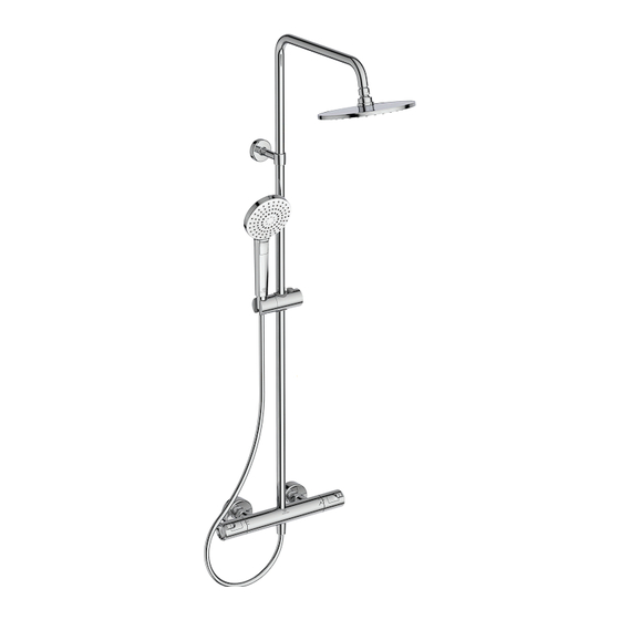
pack with overhead
Rain shower & Hand
spray
Advertisement
Table of Contents


Need help?
Do you have a question about the Ceratherm T50 A7216AA and is the answer not in the manual?
Questions and answers