Table of Contents
Advertisement
Quick Links
T750 Access Point
Quick Setup Guide
NOTE: The minimum software revision for the T750 Omni is
ZoneDirector (ZD) 10.4 or later, or SmartZone (SZ) 5.2 or later, or
standalone AP firmware 114.X or later.
This Quick Setup Guide provides step-by-step instructions on how to field-
install the Ruckus Wireless T750 Omni access point (AP). For detailed
information on planning the installation, performing a site survey, and
operating the T750 Omni, refer to the Ruckus Wireless Outdoor Access
Point User Guide, available at https://support.ruckuswireless.com.
WARNING! Only trained and qualified personnel should be allowed to
install, replace, or service this equipment. Only to be installed in
restricted access areas.
WARNING! Installation of this equipment must comply with local and
national electrical codes.
CAUTION! Make sure that you form a 80mm - 130mm (3"-5") drip loop
in any cable that is attached to the AP or the building. This will prevent
water from running along the cable and entering the AP or the building
where the cable terminates.
CAUTION! Be sure that grounding is available and that it meets local
and national electrical codes. For additional lightning protection, use
lightning rods and lightning arrestors.
CAUTION! Make sure that proper lightning surge protection
precautions are taken according to local electrical code.
WARNING! Ruckus Wireless strongly recommends that you wear eye
protection before mounting the T750 Omni.
This Guide in Other Languages
• 请从以下网站获得该指南的简体中文版
https://
support.ruckuswireless.com.
• Vous trouverez la version française de ce guide à l'adresse suivante
https://support.ruckuswireless.com.
• このガイドの日本語版は
https://support.ruckuswireless.com
ください。
• 이 가이드의 한국어 버전은 웹 사이트
(https://
support.ruckuswireless.com) 에서 확인하시기 바랍니다.
• Veja a versão em português (Brasil) deste guia em
support.ruckuswireless.com.
• Puede ver la versión en español (América Latina) de esta guía en
support.ruckuswireless.com.
Copyright
©
2022 CommScope, Inc. All rights reserved.
Published December 2022, Part Number 800-72101-001 Rev E
Before You Begin
Before deploying Ruckus Wireless products, please check for the latest
software and the release documentation.
• Release Notes and other user documentation are available at
support.ruckuswireless.com/documents.
• Software upgrades are available at
software.
• Software license and limited warranty information are available at
http://support.ruckuswireless.com/warranty.
Before deploying your Ruckus Wireless Access Point, verify that all items
listed in Package Contents are included in the package. If any item is
damaged or missing, notify your authorized Ruckus Wireless sales
representative. Also, make sure that you have the required hardware
and tools.
Required Hardware and Tools
• 1/2" (13 mm) flat-blade screwdriver or equivalent
• No. 2 Phillips screwdriver
• Small flat-blade screwdriver
• Torque wrench or torque screwdriver with sockets
• Long-nose pliers
• Electrical wire stripping and terminal crimping pliers
• Pipe, pole or a sturdy flat surface
• Electric drill with drill bits and customer-supplied wall anchors, flat
washers, and hex nuts for flat-surface mount
Package Contents
A complete T750 field installation package includes all of the items listed
below :
• T750 Access Point
• M25 data cable gland extender
• Three M25 data cable glands
• Outdoor AP Mounting Bracket kit
• One ground wire with lug
• Cloud Management Statement
• Cable gland extender gasket
• AC Connector
• Zipcord cable gland grommet
• Four 1/2" (12.7 mm) wide adjustable clamps, 2.5" (63.5 mm) diameter,
for main mounting bracket on smaller poles
• Safety cable kit
• Service Level Agreement/Limited Warranty Statement
• Declaration of Conformity
• Regulatory Statement
• Ruckus Wireless AP Getting Started Guide
• This Quick Setup Guide
でご覧
Mounting Instructions
Connecting and Sealing the RJ-45 Cables
https://
The T750 may use zero, or one or two RJ-45 cables, one for Ethernet when
configured as a Root AP (RAP), and another when the T750 is supplying
https://
PoE out to a peripheral device, such as a small cell or micro cell radio.
When the T750 uses RJ-45 cables, connect and seal the cables using the
M25 data cable glands as shown in Figure 2.
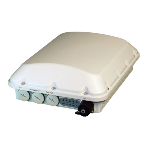
FIGURE 1 T750 AP PoE IN and PoE OUT ports
http://
http://support.ruckuswireless.com/
1. SFP port
2. PoE IN
WARNING! Do not use any PoE injector not tested and approved by
Ruckus Wireless to power the T750 Access Point.
WARNING! Do not plug PoE IN power into the PoE OUT port. See Figure
1.
1. Feed the end of the cable through the gland dome, rubber grommet,
clamping ring assembly and cable gland base, as shown in Figure 2.
FIGURE 2 RJ-45 Cable and Cable Gland Assembly
2. Use a wide flat-blade screwdriver to remove the required (PoE OUT or
PoE IN) blanking cap from the T750.
3. Connect the cable to the Ethernet port in the AP.
4. Tighten the cable gland base to 7 N.m (62 in-lbs).
5. Wrap the clamping ring assembly around the rubber grommet. Make
sure that the clamping ring assembly fully encloses the rubber
grommet.
6. Seat the clamping ring assembly and rubber grommet in the cable
gland base.
7. Hand-tighten the gland dome.
3. PoE OUT
4. AC port
NOTE: Do not seat the clamping ring and rubber grommet into the
cable gland base until the cable gland base has been torqued to
specifications.
1. SFP Port
3. Rubber grommet
2. Clamping ring
4. Gland dome
Page 1 of 4
Advertisement
Table of Contents

Related Manuals for Ruckus Wireless T750


Summary of Contents for Ruckus Wireless T750
- Page 1 • Veja a versão em português (Brasil) deste guia em https:// 6. Seat the clamping ring assembly and rubber grommet in the cable The T750 may use zero, or one or two RJ-45 cables, one for Ethernet when support.ruckuswireless.com. gland base.
- Page 2 Connecting the SFP Optic Module Using a Single Connecting the SFP Optic Module Using a Zipcord Attaching the Mounting Bracket to a Flat Surface Diameter Cable Cable 1. Place the mounting bracket at the location on the flat surface where you want to mount the AP.
- Page 3 5. Continue with Attaching the AP Bracket to the Linkage Bracket FIGURE 6 Attaching the mounting bracket to a vertical pole FIGURE 9 Attaching the AP bracket to the AP page 3. Attaching the AP Bracket to the Linkage Bracket Attach the AP bracket to the linkage bracket using the included bolt, lock washer, flat washer, serrated external-tooth washer and nut shown in the illustration below.
- Page 4 AP chassis ground point. Wire Stripping (Not Actual Size) CAUTION! The T750 AP includes one 9 mm stainless steel M6 x1 earth ground screw with split lock and flat washers. Make sure that any replacement screw is no longer than 9 mm.
Need help?
Do you have a question about the T750 and is the answer not in the manual?
Questions and answers