Table of Contents
Advertisement
Quick Links
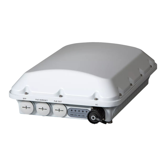
T710s Access Point
Quick Setup Guide
CAUTION!
The minimum software revision for the T710s
is ZoneDirector 9.13 or later, or SmartZone (SZ) 3.4 or later.
DO NOT CONNECT THE T710s TO A RUCKUS
WIRELESS ZONEDIRECTOR RUNNING 9.12.2 OR
EARLIER.
This Mounting Guide provides step-by-step instructions on how to
field-install the Ruckus Wireless T710s access point (AP).
For detailed information on planning the installation, performing a site
survey, and operating the T710s, refer to the Outdoor Access Point
User Guide, available at https://support.ruckuswireless.com.
WARNING: Only trained and qualified personnel should be allowed to
install, replace, or service this equipment.
WARNING: Installation of this equipment must comply with local and
national electrical codes.
CAUTION: Make sure that you form a 80mm - 130mm (3"-5") drip
loop in any cable that is attached to the AP or the building. This will
prevent water from running along the cable and entering the AP or the
building where the cable terminates.
CAUTION: Be sure that grounding is available and that it meets local
and national electrical codes. For additional lightning protection, use
lightning rods and lightning arrestors.
CAUTION: Make sure that proper lightning surge protection
precautions are taken according to local electrical code.
WARNING: Ruckus Wireless strongly recommends that you wear eye
protection before mounting the T710s.
T
G
O
L
HIS
UIDE IN
THER
ANGUAGES
请从以下网站获得该指南的简体中文版
https://support.ruckuswireless.com.
Vous trouverez la version française de ce guide à l'adresse suivante
https://support.ruckuswireless.com.
こ の ガ イ ド の⽇本語版は
https://support.ruckuswireless.com
で ご 覧 く だ さ い。
이 가이드의 한국어 버전은 웹 사이트
(https://support.ruckuswireless.com) 에서 확인하시기 바랍니다 .
Veja a versão em português (Brasil) deste guia em
https://support.ruckuswireless.com.
Puede ver la versión en español (América Latina) de esta guía en
https://support.ruckuswireless.com.
Copyright © 2017 Ruckus Wireless, Inc.
Published April 2017, Part Number 800-71212-001 Rev B
B
Y
B
EFORE
OU
EGIN
Before deploying your Ruckus Wireless T710s, verify that all items
listed in
Package Contents
are included in the package. If any item is
damaged or missing, notify your authorized Ruckus Wireless sales
representative. Also, make sure that you have the required hardware
and tools.
R
H
T
EQUIRED
ARDWARE AND
OOLS
•
Customer-supplied outdoor-rated three-wire (1-2mm
18AWG) AC cable
•
1/2" (13mm) flat-blade screwdriver or equivalent
•
No. 2 Phillips screwdriver
•
Small flat-blade screwdriver
•
Torque wrench or torque screwdriver with sockets
•
Long-nose pliers
•
Electrical wire stripping and terminal crimping pliers
•
Pipe or pole --OR-- a sturdy flat surface
•
Electric drill with drill bits and customer-supplied wall anchors, flat
washers, and hex nuts for flat-surface mount
•
Four factory-supplied 1/2" (12.7mm) wide stainless steel
adjustable clamps, 2.5" (63.5mm) diameter, for main mounting
bracket on smaller poles
•
Ruler
P
C
ACKAGE
ONTENTS
A complete T710s field installation package includes all of the items
listed below (see Figure 1for illustrations):
•
T710s Access Point (A)
•
M25 data cable gland extender (B)
•
Three M25 data cable glands (C)
•
Outdoor AP Mounting Bracket (D)
•
AC Power Cable End Connector (E)
•
Cable Gland Extender Flat Gasket (F)
•
Safety cable kit (G)
•
One ground wire with lug (H)
•
Service Level Agreement/Limited Warranty Statement
•
Regulatory Statement
•
Ruckus Wireless AP Getting Started Guide
•
Declaration of Conformity
•
This Quick Setup Guide
Figure 1:
Package Contents
2
or 14-
T710
S
A
S
ECTOR
The T710s 120-Degree Sector AP is best deployed where
internal-antenna beamforming can provide extended reach and
throughput to a 120-degree coverage area. See Figure 2 for the
azimuth coverage pattern, and see Figure 3 for the elevation
coverage pattern.
Figure 2:
Typical AP sector azimuth plane coverage, top view
C
NTENNA
OVERAGE
Extended
120º Reach
Page 1 of 4
Advertisement
Table of Contents

Related Manuals for Ruckus Wireless T710s


Summary of Contents for Ruckus Wireless T710s
- Page 1 Four factory-supplied 1/2” (12.7mm) wide stainless steel For detailed information on planning the installation, performing a site survey, and operating the T710s, refer to the Outdoor Access Point adjustable clamps, 2.5” (63.5mm) diameter, for main mounting User Guide, available at https://support.ruckuswireless.com.
- Page 2 Flat Surface Step 3b: Attaching the Mounting Bracket to a ring. T710s is supplying PoE out to a peripheral device, such as a small cell Metal Pole or micro cell radio. When the T710s uses RJ-45 cables, connect and Seat the clamping ring assembly and rubber O-ring in the cable seal the cables using the M25 data cable glands as shown in Figure 5.
- Page 3 - 3 (not used) NOTE: The color coding of wire conductors varies by region. Before completing this step, check your local wiring standards for guidance. Copyright © 2017 Ruckus Wireless, Inc. Page 3 of 4 Published April 2017, Part Number 800-71212-001 Rev B...
- Page 4 AP chassis ground point (Figure 14). CAUTION: The T710s AP includes one 12mm stainless steel M6x1 earth ground screw with split lock and flat washers. Make sure that any replacement screw is no longer than 12mm. If a screw is longer than 12mm, it can damage the AP chassis.
Need help?
Do you have a question about the T710s and is the answer not in the manual?
Questions and answers