Table of Contents
Advertisement
Quick Links
T710 Access Point
Mounting Guide
CAUTION!
THE MINIMUM SOFTWARE REVISION FOR
THE T710 IS ZONEFLEX (ZF) 9.12.2 OR LATER.
DO NOT CONNECT THE T710 TO A RUCKUS
WIRELESS CONTROLLER WITH ZF 9.12.1 OR
EARLIER.
This Mounting Guide provides step-by-step instructions on how to
field-install the Ruckus Wireless ZoneDirector T710 access point (AP).
For detailed information on planning the installation, performing a site
survey, and operating the T710, refer to the ZoneFlex Outdoor Access
Point User Guide, available at https://support.ruckuswireless.com.
WARNING:
Only trained and qualified personnel should be allowed to
install, replace, or service this equipment.
WARNING:
Installation of this equipment must comply with local and
national electrical codes.
CAUTION:
Make sure that you form a 80mm - 130mm (3"-5") drip
loop in any cable that is attached to the AP or the building. This will
prevent water from running along the cable and entering the AP or the
building where the cable terminates.
CAUTION:
Be sure that grounding is available and that it meets local
and national electrical codes. For additional lightning protection, use
lightning rods and lightning arrestors.
CAUTION:
Make sure that proper lightning surge protection
precautions are taken according to local electrical code.
WARNING:
Ruckus Wireless strongly recommends that you wear eye
protection before mounting the T710.
T
G
O
L
HIS
UIDE IN
THER
ANGUAGES
请从以下网站获得该指南的简体中文版
https://support.ruckuswireless.com.
Vous trouverez la version française de ce guide à l'adresse suivante
https://support.ruckuswireless.com.
こ の ガ イ ド の⽇本語版は
https://support.ruckuswireless.com
で ご 覧 く だ さ い。
이 가이드의 한국어 버전은 웹 사이트
(https://support.ruckuswireless.com) 에서 확인하시기 바랍니다 .
Veja a versão em português (Brasil) deste guia em
https://support.ruckuswireless.com.
Puede ver la versión en español (América Latina) de esta guía en
https://support.ruckuswireless.com.
Copyright © 2015 Ruckus Wireless, Inc.
Published November 2015, Part Number 800-70398-001 Rev A
B
Y
B
EFORE
OU
EGIN
Before deploying your Ruckus Wireless T710, verify that all items listed
in
Package Contents
are included in the package. If any item is
damaged or missing, notify your authorized Ruckus Wireless sales
representative. Also, make sure that you have the required hardware
and tools.
R
H
T
EQUIRED
ARDWARE AND
OOLS
•
Customer-supplied outdoor-rated three-wire (1-2mm
18AWG) AC cable
•
Customer-supplied earth-ground wire (3-5mm
•
1/2" (13mm) flat-blade screwdriver or equivalent
•
No. 2 Phillips screwdriver
•
Small flat-blade screwdriver
•
Torque wrench or torque screwdriver with sockets
•
Long-nose pliers
•
Electrical wire stripping and terminal crimping pliers
•
Pipe or pole --OR-- a sturdy flat surface
•
Electric drill with drill bits and customer-supplied wall anchors, flat
washers, and hex nuts for flat-surface mount
•
Two customer-supplied M16 (5/8") carriage bolts for main
mounting bracket on a wooden pole
•
Four customer-supplied 6mm (1/4") bolts or screws for main
mounting bracket --OR--
Four customer-supplied 14mm (1/2") bolts or screws for main
mounting bracket --OR--
Four factory-supplied 1/2" (12.7mm) wide stainless steel adjust-
able clamps, 2.5" (63.5mm) diameter, for main mounting bracket
on smaller poles --OR--
Two 7/8" customer-supplied (22mm) wide stainless steel adjust-
able clamps for main mounting bracket on larger poles
•
Ruler
P
C
ACKAGE
ONTENTS
A complete T710 field installation package includes all of the items
listed below:
•
T710 Access Point (A in Figure 1), includes crimp-type earth-
ground ring terminal
•
Two M25 data cable glands (B in Figure 1)
•
One main mounting bracket (C in Figure 1)
•
One U-joint bracket (D in Figure 1)
•
Nine sets 12mm M6 x 1 hex bolt with lock and flat washers
(E in Figure 1)
•
One hook bracket (F in Figure 1)
•
One set 70mm M8x1.25 hex bolt with spring lock and flat
washers (G in Figure 1)
•
One AP attachment bracket (H in Figure 1)
•
Four SAE32 steel clamps, 2.5-inch diameter (I in Figure 1)
•
One AC power cable input end connector and cap
(J in Figure 1)
•
One safety cable (K in Figure 1)
•
This Mounting Guide
Figure 1:
T710 field-installation package contents
A
2
or 14-
2
or 10-12 AWG)
The field installation package can also include:
•
Service Level Agreement/Limited Warranty Statement
•
Regulatory Statement
•
Registration card
•
Declaration of Conformity, if required
NOTE: This kit can include extra screws, nuts and washers. You may
use the extras wherever required.
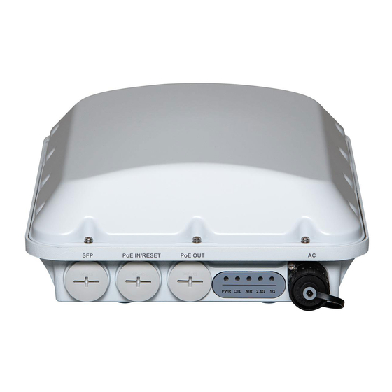
S
1: C
TEP
ONNECTING AND
C
ABLES
The T710 may use zero, or one or two RJ-45 cables, one for Ethernet
when configured as a Root AP (RAP), and one when the T710 is
supplying PoE out to a peripheral device, such as a small cell or micro
cell radio. When the T710 uses RJ-45 cables, connect and seal the
cables using the M25 data cable glands (B in Figure 1).
1
Feed the end of the cable through the sealing nut, rubber O-ring,
clamping ring assembly and cable gland base as shown in Figure
2.
Figure 2:
RJ-45 cable and cable gland assembly
2
Use a wide flat-blade screwdriver to remove the required (RESET/
PoE OUT or PoE IN) blanking cap from the T710.
3
Connect the cable to the Ethernet port in the T710.
4
Tighten the cable gland base into the T710 chassis to 7 N.m or
62 in-lbs.
B
C
D
E
F
G
H
J
K
S
RJ-45
EALING THE
Cable gland base
Clamping ring assembly
Rubber O-ring
Sealing nut
Page 1 of 4
I
Advertisement
Table of Contents

Related Manuals for Ruckus Wireless T710


Summary of Contents for Ruckus Wireless T710
-
Page 1: Mounting Guide
ABLES install, replace, or service this equipment. mounting bracket --OR-- The T710 may use zero, or one or two RJ-45 cables, one for Ethernet WARNING: Installation of this equipment must comply with local and Four customer-supplied 14mm (1/2“) bolts or screws for main when configured as a Root AP (RAP), and one when the T710 is national electrical codes. - Page 2 Figure 7. Typical AC wire colors: (Earth Ground): Green (US), Green/Yellow (EU) - 1 (Neutral/Return): White or Gray (US), Blue (EU) Copyright © 2015 Ruckus Wireless, Inc. Page 2 of 4 Published November 2015, Part Number 800-70398-001 Rev A...
- Page 3 Neutral/Return Line/Hot (not used) Two different-sized grommets are supplied in the AC connector NOTE: After a reset, you can access the internal T710 AP web AP F ROUBLESHOOTING EPLACING THE USES assembly kit. Use the grommet that is appropriate to the diameter interface using https://192.168.0.1.
- Page 4 Front cover screw-tightening pattern Keep Clear Sky View Re-apply power to the T710. You have completed replacing the fuses in the T710. Copyright © 2015 Ruckus Wireless, Inc. Page 4 of 4 Published November 2015, Part Number 800-70398-001 Rev A...
Need help?
Do you have a question about the T710 and is the answer not in the manual?
Questions and answers