Table of Contents
Advertisement
Quick Links
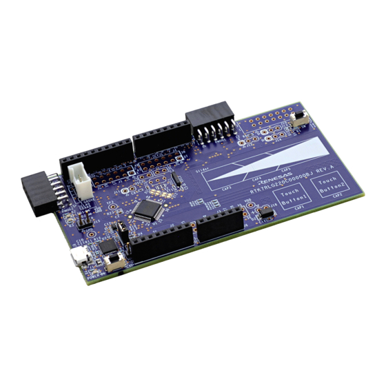
RL78/G22
Fast Prototyping Board
16
16-Bit Single-Chip Microcontrollers
RL78 Family
All information contained in these materials, including products and product specifications, represents
information on the product at the time of publication and is subject to change by Renesas Electronics
Corp. without notice. Please review the latest information published by Renesas Electronics Corp.
through various means, including the Renesas Electronics Corp. website (http://www.renesas.com).
www.renesas.com
User's Manual
Rev.1.00 Nov 2022
Advertisement
Table of Contents

Related Manuals for Renesas RL78/G22


Summary of Contents for Renesas RL78/G22
- Page 1 All information contained in these materials, including products and product specifications, represents information on the product at the time of publication and is subject to change by Renesas Electronics Corp. without notice. Please review the latest information published by Renesas Electronics Corp.
- Page 2 Renesas Electronics disclaims any and all liability for any damages or losses incurred by you or any third parties arising from the use of any Renesas Electronics product that is inconsistent with any Renesas Electronics data sheet, user’s manual or other Renesas Electronics document.
- Page 3 Unit Products The following usage notes are applicable to all Microprocessing unit and Microcontroller unit products from Renesas. For detailed usage notes on the products covered by this document, refer to the relevant sections of the document as well as any technical updates that have been issued for the products.
- Page 4 The revision history summarizes the locations of revisions and additions. It does not list all revisions. Refer to the text of the manual for details. The following documents apply to the RL78/G22 Fast Prototyping Board. Be sure to refer to the latest versions of these documents.
- Page 5 Digilent Inc. For the Pmod™ interface specification, refer to the Pmod™ License Agreement page at the Web site of Digilent Inc. Random Access Memory Renesas Flash Programmer Read Only Memory Serial Peripheral Interface Timer Pulse Unit UART Universal Asynchronous Receiver/Transmitter...
-
Page 6: Table Of Contents
Table of Contents 1. Overview ..........................1 Purpose ..............................1 Features ..............................1 Preparation ..............................1 1.3.1 Installing the e studio IDE ....................... 2 1.3.2 Installing the CS+ IDE ........................2 Board Specification Table .......................... 3 Block Diagram ............................4 2. -
Page 7: Overview
This user’s manual describes the RL78/G22 Fast Prototyping Board (RTK7RLG220C00000BJ) (hereinafter referred to as “this product”). Purpose This product is an evaluation tool for a Renesas MCU. This user’s manual describes the hardware specifications, ways of setting switches, and the basic setup procedure. Features This product can handle the following tasks. -
Page 8: Installing The E Studio Ide
3. Select “RL78” for [Device Families]. 4. Confirm that the latest version of Renesas CCRL has been selected as the compiler. 5. Select the [I accept the terms of the Software Agreements] checkbox and then click on the [Install] button. -
Page 9: Board Specification Table
RL78/G22 Fast Prototyping Board 1. Overview Board Specification Table Table 1-1 shows the board specifications. Table 1-1 Board Specification Table Item Specification Part No.: R7F102GGE2DFB Evaluation MCU (RL78/G22) Package: 48-pin LFQFP On-chip memory: 64-KB ROM, 4-KB RAM, 2-KB data flash memory Board size 53.34 mm x 99.06 mm... -
Page 10: Block Diagram
RL78/G22 Fast Prototyping Board 1. Overview Block Diagram Figure 1-1 shows the block diagram of this product. Arduino Grove MCU header Pmod Power connector connector connector Power- supply circuit Evaluation MCU Emulator (RL78/G22) connector USB-to-serial connector converter Reset switch... -
Page 11: Board Layout
RL78/G22 Fast Prototyping Board 2. Board Layout 2. Board Layout Figure 2-1 shows the external appearance of the top side of this product. Ten digital pins for Arduino Eight digital pins for Arduino MCU headers Pmod Type 6A... -
Page 12: Parts Layout
RL78/G22 Fast Prototyping Board 3. Parts Layout 3. Parts Layout Figure 3-1 shows the parts layout of this product. Figure 3-1 Parts Layout Figure 3-2 shows the external dimensions of this product. Unit: mm Figure 3-2 External Dimensions R20UT5121EJ0100 Rev. 1.00 Page 6 of 35 Nov.16.22... -
Page 13: Operating Environment
RL78/G22 Fast Prototyping Board 4. Operating Environment 4. Operating Environment Figure 4-1 shows the operating environment of this product. Install the IDE on the host PC. USB cable RL78/G22 Fast Prototyping Board Host PC Figure 4-1 Operating Environment R20UT5121EJ0100 Rev. 1.00 Page 7 of 35 Nov.16.22... -
Page 14: User Circuits
5. User Circuits Evaluation MCU The specifications for the power supply, system clock, and reset of the evaluation MCU (RL78/G22) at the time of shipment are as follows. Power supply: 5 V (VBUS) supplied from the USB (including the analog power supply) •... -
Page 15: Arduino Connectors
RL78/G22 Fast Prototyping Board 5. User Circuits Arduino Connectors The specification of the Arduino connectors is on the assumption that Arduino shields are to be connectable. However, we do not guarantee connection to all types of Arduino ... - Page 16 RL78/G22 Fast Prototyping Board 5. User Circuits Table 5-1 Pin Assignments of the Arduino Connectors (1/2) Part No. in Name of RL78/G22 the Circuit Arduino Power Port Analog Serial Schematics Signal* Supply J5-1 N.C. J5-2 IOREF J5-3 RESET...
- Page 17 RL78/G22 Fast Prototyping Board 5. User Circuits Table 5-2 Pin Assignments of the Arduino Connectors (2/2) Part No. in Name of RL78/G22 the Circuit Arduino Power Port Analog Serial Schematics Signal* Supply J7-1 RX/0 RxD1 J7-2 TX/1 TxD1...
-
Page 18: Pmod Tm Connectors
Pmod1 is assumed to be connected to the Pmod Interface Type 6A module*. Pmod2 is assumed to be connected to the Pmod Interface Type 2A or 3A module*. Note: For details on the Pmod module from Renesas, refer to the Web site at: https://www.renesas.com/quickconnect. - Page 19 RL78/G22 Fast Prototyping Board 5. User Circuits Table 5-3 Pin Assignments of Pmod (Pmod1) Pin No. of Name of RL78/G22 Pmod Pmod Power Port SPI (CSI) UART Signal Supply INTP4 RESET SO20 6(7) (P74/SI01)* SCL01 7(6) (P75/SCK01)* SDA01 - -...
-
Page 20: Mcu Headers
RL78/G22 Fast Prototyping Board 5. User Circuits MCU Headers The MCU headers are provided as through holes J1 to J4 for a total of 12 (6 x 2) pins. The pin headers have a pitch of 2.54 mm and the evaluation MCU is connected to the through holes for the headers. - Page 21 RL78/G22 Fast Prototyping Board 5. User Circuits Table 5-6 Pin Assignments of the MCU Headers (J2) Part No. in Name of RL78/G22 the Circuit Arduino Power Port and Peripheral Modules Others Schematics Signal* Supply J2-1 P50/TS00/INTP1/SI11/SDA11 J2-2 P51/TS28/INTP2/SO11 J2-3...
- Page 22 RL78/G22 Fast Prototyping Board 5. User Circuits Table 5-7 Pin Assignments of the MCU Headers (J3) Part No. in Name of RL78/G22 the Circuit Arduino Power Port and Peripheral Modules Others Schematics Signal* Supply J3-1 P27/ANI7/TS25 J3-2 (26) P26/ANI6/TS24...
- Page 23 RL78/G22 Fast Prototyping Board 5. User Circuits Table 5-8 Pin Assignments of the MCU Headers (J4) Part No. in Name of RL78/G22 the Circuit Arduino Power Port and Peripheral Modules Others Schematics Signal* Supply J4-1 P120/ANI19 J4-2 P41/TI07/TO07 J4-3...
-
Page 24: Grove Connector
MCU clocks, refer to the RL78/G22 User’s Manual: Hardware. For details on the clock circuit of this product, refer to the circuit schematics of the RL78/G22 Fast Prototyping Board. Table 5-10 shows the details of the clocks on the RL78/G22 Fast Prototyping Board. -
Page 25: Reset Switch
RL78/G22 Fast Prototyping Board 5. User Circuits 5.11 Reset Switch Pressing the reset switch (RST) applies a hardware reset to the evaluation MCU. 5.12 User Switch An optional user switch (SW) is mounted. It is connected to pin 43 of the evaluation MCU, which operates as pin function P137. -
Page 26: Usb-To-Serial Converter Reset Header
RL78/G22 Fast Prototyping Board 5. User Circuits 5.14 USB-to-Serial Converter Reset Header The USB-to-serial converter is placed in the forced reset state by short-circuiting its reset header (J15). If the evaluation MCU alone is to operate without the use of the RL78 COM port debug tool, place the USB-to-serial converter in the reset state. -
Page 27: Power-Supply Selection Header
RL78/G22 Fast Prototyping Board 5. User Circuits 5.15 Power-Supply Selection Header The operating power (VDD) of the evaluation MCU can be changed to supply from the emulator or external power, and to 5 V or 3.3 V with the use of a header (J17). Only change the jumper setting of J17 while power is not being supplied. -
Page 28: External Power Supply
RL78/G22 Fast Prototyping Board 5. User Circuits Power-supply selection header (J17) Open-circuit: emulator or external power Figure 5-7 Setting of the Header to Select Supply from the Emulator or External Power (Top Side) 5.16 External Power Supply When the evaluation MCU is to have a desired power-supply voltage, or when more current is required, use an external power supply. -
Page 29: Current Measurement Header
RL78/G22 Fast Prototyping Board 5. User Circuits 5.17 Current Measurement Header This header (J11) is used to measure the current drawn by the evaluation MCU (J11 header components are not mounted). Connecting an ammeter to this product enables measurement of the current being drawn by the evaluation MCU. -
Page 30: Pattern For Cutting The I/O Power Supply For The Usb-To-Serial Converter
RL78/G22 Fast Prototyping Board 5. User Circuits 5.18 Pattern for Cutting the I/O Power Supply for the USB-to-Serial Converter If you intend to use this board without connecting a USB connector, cut the given pattern for cutting (VCCIO). Figure 5-11 shows the position of the pattern for cutting. -
Page 31: Emulator Connector
This 14-pin connector (J10) is used to connect this product to an on-chip debugging E2 emulator or E2 emulator Lite, from Renesas Electronics, incorporating programming facilities (the connector is not mounted). The emulator is used for programming or debugging the evaluation MCU. - Page 32 RL78/G22 Fast Prototyping Board 5. User Circuits After the changes to the circuit have been made to connect the emulator as described in the previous page, if you want to restore the settings to those for COM port debugging with the use of the USB-to-serial converter, make the following change of setting as follows.
-
Page 33: Handling Precautions
RL78/G22 Fast Prototyping Board 6. Handling Precautions 6. Handling Precautions Power to be Supplied When power is supplied to this product from an emulator or through the USB, note that the total current of VDD, 5 V, and 3.3 V should not exceed the maximum current of 200 mA. - Page 34 RL78/G22 Fast Prototyping Board 6. Handling Precautions In the circuit schematics, the symbol below indicates that there are only short-circuit pads without any pattern for cutting. R20UT5121EJ0100 Rev. 1.00 Page 28 of 35 Nov.16.22...
-
Page 35: Power Supplies And Usage Conditions
J17: open-circuit • 5.0 V Notes: 1. Connecting the RL78/G22 Fast Prototyping Board to an Arduino shield, a Pmod module, or a Grove module shall be conducted at the user’s own responsibility and should only proceed after confirming the specifications of the power supply and interfaces. -
Page 36: Note On Using Qe For Capacitive Touch
RL78/G22 Fast Prototyping Board 6. Handling Precautions Note on Using QE for Capacitive Touch When you are using QE for Capacitive Touch (QE) with this product, change the circuits in the following cases (1) and (2). For the methods for developing touch applications with the use of QE, refer to the application note “RL78 Family Using QE and SIS to Develop Capacitive Touch Applications”... - Page 37 RL78/G22 Fast Prototyping Board 6. Handling Precautions (2) Not using the serial connection function of QE After the changes to the circuit have been made as described under “(1) Usage with the serial connection function of QE”, if you want to restore the settings to those for COM port debugging (including the case of the usage described under note above), make the following change of setting as follows.
-
Page 38: Note On Using P12/Txd0
UART transmission to the P12/TxD0 line is written to the target MCU before the host PC recognizes the USB-to-serial converter as the COM port, the operation of the USB-to-serial converter may be unstable and prevent connection to the Renesas Flash Programmer or terminal software. -
Page 39: Developing Code
[Target Device]: Select [R7F102GGE]. • [Connection with Target Board]: • [COM Port]: Select the COM port number for assignment to the RL78/G22 FPB from the pull-down list. [Reset control pin]: Select [DTR]. R7F102GGE Figure 7-1 Settings of the e studio R20UT5121EJ0100 Rev. -
Page 40: Using Com Port Debugging With Cs
RL78/G22 Fast Prototyping Board 7. Developing Code Using COM Port Debugging with CS+ Figure 7-2 and Figure 7-3 show the settings of CS+ when it is to be connected to the RL78/G22 Fast Prototyping Board. [Using Debug Tool]: • Select [RL78 COM Port] from [Using Debug Tool] in the [Debug] menu. -
Page 41: Additional Information
Copyright This document may be, wholly or partially, subject to change without notice. All rights reserved. Duplication of this document, either in whole or part is prohibited without the written permission of Renesas Electronics Europe Limited. © 2022 Renesas Electronics Corporation. All rights reserved. - Page 42 Revision History RL78/G22 Fast Prototyping Board User’s Manual Rev. Date Description Page Summary 1.00 Nov.16.22 First Edition issued...
- Page 43 RL78/G22 Fast Prototyping Board User’s Manual Publication Date: Rev.1.00 Nov.16.22 Published by: Renesas Electronics Corporation...
- Page 44 RL78/G22 R20UT5121EJ0100...
- Page 45 Mouser Electronics Authorized Distributor Click to View Pricing, Inventory, Delivery & Lifecycle Information: Renesas Electronics RTK7RLG220C00000BJ...
Need help?
Do you have a question about the RL78/G22 and is the answer not in the manual?
Questions and answers