Table of Contents
Advertisement
Quick Links
Advertisement
Table of Contents

Subscribe to Our Youtube Channel
Related Manuals for Planet Networking & Communication ICA-E3550V


Summary of Contents for Planet Networking & Communication ICA-E3550V
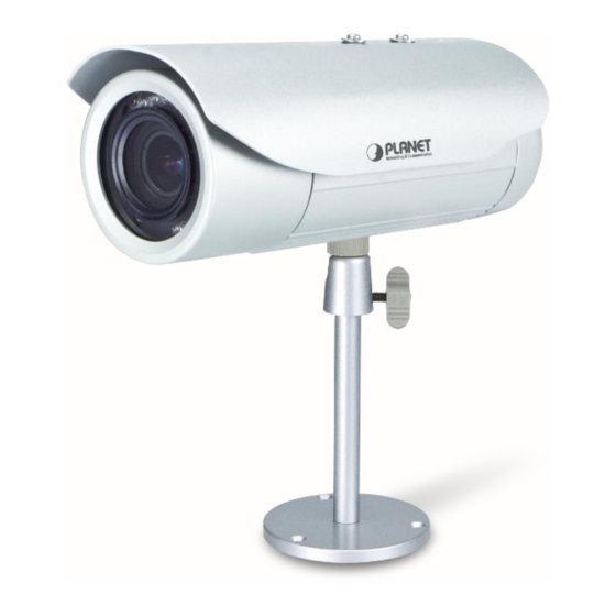
- Page 1 5 Mega-pixel Bullet IR PoE IP Camera with Extended Support ►ICA-E3550V...
- Page 2 5 Mega-pixel Bullet IR PoE IP Camera ICA-E3550V Copyright Copyright 2018 by PLANET Technology Corp. All rights reserved. No part of this publication may be reproduced, transmitted, transcribed, stored in a retrieval system, or translated into any language or computer language, in any form or by any means, electronic, mechanical, magnetic, optical, chemical, manual or otherwise, without the prior written permission of PLANET.
- Page 3 Do not dispose of WEEE as unsorted municipal waste; they should be collected separately. Revision User’s Manual of PLANET 5 Mega-pixel Bullet IR PoE IP Camera Model: ICA-E3550V Rev: 1.2 (August, 2018) Part No. EM-ICA-E3550V_v1.2...
-
Page 4: Table Of Contents
1.4 Product Specifications ............................11 Chapter 2. Hardware Interface ......................13 2.1 Physical Descriptions ............................13 2.1.1 Identification of ICA-E3550V connectors ....................13 2.1.2 I/O Control Instruction ..........................14 2.2 Hardware Installation ............................17 2.3 Initial Utility Installation ............................18 2.4 Using UPnP of Windows XP or 7 ........................21 2.4.1 Windows XP ............................ - Page 5 5 Mega-pixel Bullet IR PoE IP Camera ICA-E3550V 3.10.1 Event Server ............................74 3.10.2 Event Configuration ..........................77 3.10.3 Event List .............................. 85 3.10.4 Manual Event ............................89 3.11 System ................................89 3.11.1 User Account ............................89 3.11.2 System Info ............................90 3.11.3 Factory Default ............................
-
Page 6: Chapter 1. Product Introduction
1.2 Overview Extended Support with Specific Software PLANET E-series of IP cameras, ICA-E3550V and ICA-E5550V, are able to provide advanced surveillance monitoring applications with specific software such as video analytics and vehicle license plate recognition. Firstly, through the NVR-E6480, it can help users monitor and record images/videos... - Page 7 Day & Night Functionality To adapt to constantly changing lighting conditions during the day and night, the ICA-E3550V comes with a removable IR-cut filter and built-in IR illuminators, which enable the camera to provide color video...
- Page 8 5 Mega-pixel Bullet IR PoE IP Camera ICA-E3550V when there is sufficient light, and black/white video in dark conditions. The ICA-E3550V is able to maintain clear images 24 hours a day. Exceptional Image Quality Together with powerful image processing attributes like Wide Dynamic Range (WDR) and 3-dimensional Noise Reduction (3DNR) technology, the ICA-E3550V is able to filter the intense backlight surrounding a subject and remove noises from video signal.
- Page 9 Flexible Installation and Power Functionality The ICA-E3550V incorporates IEEE 802.3af Power over Ethernet technology and can be powered from a PoE sourcing equipment via the network, which eliminates the need for power cables and reduces installation costs.
-
Page 10: Features
5 Mega-pixel Bullet IR PoE IP Camera ICA-E3550V 1.3 Features Camera ■ 1/3.2” 5MP progressive scan CMOS sensor ■ 2.8~12 mm vari-focal, fixed-iris lens ■ 0.1 lux minimum illumination at F1.4 ■ Maximum resolution 2592 x 1944 ■ Removable IR-cut filter for Day & Night function ... -
Page 11: Product Specifications
5 Mega-pixel Bullet IR PoE IP Camera ICA-E3550V 1.4 Product Specifications Model ICA-E3550V Camera Image Device 1/3.2" 5 mega-pixel progressive scan CMOS Sensor Vari-focal 2.8~12 mm, fixed-iris Lens Mechanical IR-cut filter Angle of view: horizontal: 28.2~69.2 degrees Min. Illuminator 0.1 lux @ F1.4... - Page 12 5 Mega-pixel Bullet IR PoE IP Camera ICA-E3550V anonymous login, 802.1X network access control 10 simultaneous unicast users Users System Integration Application Programming Software Development Kit (SDK) available; ONVIF compliant Interface Alarm Triggering Video motion detection (3 regions) Notify control center; Change camera settings; Command other devices;...
-
Page 13: Chapter 2. Hardware Interface
ICA-E3550V Chapter 2. Hardware Interface 2.1 Physical Descriptions 2.1.1 Identification of ICA-E3550V connectors 1. Memory Card Slot: Supports microSDHC and microSDXC cards. Insert a memory card (not included) into this slot for local recording purposes. 2. Reset Button: Uses the Reset Button to reset the camera to its factory default settings. To do the reset, press and hold the Reset button for at least 5 seconds or until the Power LED lights up. -
Page 14: I/O Control Instruction
5 Mega-pixel Bullet IR PoE IP Camera ICA-E3550V 5. Audio Input Connect to audio input devices, such as a microphone with built-in amplifier, etc. 6. Audio Output Connect to audio output devices, such as a speaker, etc. 7. Digital Input/Output Connect to digital input or output devices, such as an alarm trigger, panic button, etc. - Page 15 5 Mega-pixel Bullet IR PoE IP Camera ICA-E3550V 3) Typical Connection Based on these specifications, if the DI device has a voltage of 0V ~ 30V or the DO device has a voltage of < 24V (< 50mA), then the camera can supply internal power to these devices and there is no need to connect the DI/DO device to an external power source.
- Page 16 5 Mega-pixel Bullet IR PoE IP Camera ICA-E3550V The illustration below is a graphic example of connecting a relay to a high voltage DO device. 110V-220V AC External Power Source Relay (DO1 Device) Camera Illuminator...
-
Page 17: Hardware Installation
5 Mega-pixel Bullet IR PoE IP Camera ICA-E3550V 2.2 Hardware Installation 1. Place the Camera on the ceiling or fix it onto wall Use three screws to fix the bracket plate onto the ceiling or wall. 2. Plug an Ethernet cable into the Camera Connect an Ethernet cable to the LAN socket located on the Network Camera’s bottom and attach it... -
Page 18: Initial Utility Installation
5 Mega-pixel Bullet IR PoE IP Camera ICA-E3550V 2.3 Initial Utility Installation This chapter shows how to quickly set up your H.264 camera. The camera is with the default settings. However, to help you find the networked camera quickly, the windows utility PLANET Smart Discovery Lite can search the cameras in the network that will help you to configure some basic settings before you start advanced management and monitoring. - Page 19 5 Mega-pixel Bullet IR PoE IP Camera ICA-E3550V screen shows. If there is no DHCP server in the network, the default IP of camera is 192.168.0.20. (1) This utility shows all necessary information from the devices, such as MAC address, device name, firmware version and device IP subnet address.
- Page 20 5 Mega-pixel Bullet IR PoE IP Camera ICA-E3550V 5. If the user name and password are input correctly, the following web page will be displayed.
-
Page 21: Using Upnp Of Windows Xp Or 7
5 Mega-pixel Bullet IR PoE IP Camera ICA-E3550V 2.4 Using UPnP of Windows XP or 7 2.4.1 Windows XP UPnP™ is short for Universal Plug and Play, which is a networking architecture that provides compatibility among networking equipment, software, and peripherals. This device is an UPnP enabled device. - Page 22 5 Mega-pixel Bullet IR PoE IP Camera ICA-E3550V The “Add or Remove Programs” will display on the screen and click Add/Remove Widows Components to continue.
- Page 23 5 Mega-pixel Bullet IR PoE IP Camera ICA-E3550V The following screen will appear; select “Networking Services” and click “Details” to continue. The “Networking Services” will be displayed on the screen; select “Universal Plug and Play” and click “OK” to continue.
- Page 24 5 Mega-pixel Bullet IR PoE IP Camera ICA-E3550V Please click “Next” to continue. The program will start installing the UPnP automatically. You will see the pop-up screen as shown below. Please wait while Setup configures the components.
-
Page 25: Windows 7
5 Mega-pixel Bullet IR PoE IP Camera ICA-E3550V Please click “Finish” to complete the UPnP installation Double-click “My Network Places” on the desktop; the “My Network Places” will be displayed on the screen and double-click the UPnP icon with Internet Camera to view your device in an Internet browser. - Page 26 5 Mega-pixel Bullet IR PoE IP Camera ICA-E3550V password or confirmation, type the password or provide confirmation.
- Page 27 5 Mega-pixel Bullet IR PoE IP Camera ICA-E3550V...
-
Page 28: Setting Up Activex For Internet Camera
5 Mega-pixel Bullet IR PoE IP Camera ICA-E3550V 2.5 Setting Up ActiveX for Internet Camera The Internet Camera web pages communicate with the Internet Camera using an ActiveX control. The ActiveX control must be downloaded from the Internet Camera and installed on your PC. Your Internet Explorer security settings must allow for the web page to work correctly. -
Page 29: Internet Explorer 7 For Windows Xp
5 Mega-pixel Bullet IR PoE IP Camera ICA-E3550V By now, you have finished your entire PC configuration for Internet Camera. 2.5.2 Internet Explorer 7 for Windows XP From your IE browser “Tools” “Internet Options…” “Security” ”Custom Level…”, please set up your “Settings”... - Page 30 5 Mega-pixel Bullet IR PoE IP Camera ICA-E3550V • Enable “Automatic prompting for ActiveX controls” • Prompt “Initialize and script active controls not marked….” From your IE browser “Tools” “Internet Options…” “Security” “Trusted Sites” “Custom Level…”, please set up your “Settings” as follows: •...
-
Page 31: Chapter 3. Web-Based Management
5 Mega-pixel Bullet IR PoE IP Camera ICA-E3550V Chapter 3. Web-based Management This chapter provides setup details of the Internet Camera’s Web-based Interface. 3.1. Introduction The Internet Camera can be configured with your Web browser. Before configuring, please make sure your PC is under the same IP segment as Internet Camera. -
Page 32: Live Viewing
5 Mega-pixel Bullet IR PoE IP Camera ICA-E3550V If the User Name and Password have been changed with PLANET IP Utility, please enter the new User Name and Password here. After logging on, you should see the following messages at the bottom of Internet Explorer. - Page 33 5 Mega-pixel Bullet IR PoE IP Camera ICA-E3550V 1920x1080 (2-5MP cameras). While being on the Live View page, the Live View icon appears as being pressed. If you leave the Live View page, you can later return by pressing that button. The buttons shown on the Live View page vary depending on the functions supported by the camera.
- Page 34 5 Mega-pixel Bullet IR PoE IP Camera ICA-E3550V Configurator’s Setup page. To see how each of the streams looks like, there are quick buttons on the Live View page: - Show Stream 1 video - Show Stream 2 video When pressing the Stream 2 button, the Live View would look like this: To capture the snapshots of the current live view, press the snapshot button.
-
Page 35: Configuration
5 Mega-pixel Bullet IR PoE IP Camera ICA-E3550V Audio level adjusted to the maximum: This volume control appears on the user interface only when the Audio-in function of the camera has been “Enabled” under the Setup page. The digital output controls appear on the Live View page of the cameras with digital input/output function. -
Page 36: Host Setup
5 Mega-pixel Bullet IR PoE IP Camera ICA-E3550V 3.5 Host Setup The “Host Setup” section allows the administrator to define the name of the camera and preferred user interface language. 3.5.1 Host Parameters Description Host Name Host Name is used to identify the camera by a DHCP server. In some... -
Page 37: Gps Position
5 Mega-pixel Bullet IR PoE IP Camera ICA-E3550V 3.5.2 GPS Position This section allows users to manually set the GPS position of the camera and find the location of the camera on the map when using a Network Video Recorder (NVR). - Page 38 5 Mega-pixel Bullet IR PoE IP Camera ICA-E3550V There are two ways to adjust the date and time – automatically by getting date and time regularly from any of the NTP servers worldwide, or manually by selecting proper time zone, date and time. The automatic way can be used only if the camera has an access to NTP servers.
-
Page 39: Network
5 Mega-pixel Bullet IR PoE IP Camera ICA-E3550V Type 1 – define the starting or ending time of daylight saving period by the number of the week in the month (First, Second, Third or Last week). Type 2 – define the starting or ending time of daylight saving period by the exact date in the month (1- 31). - Page 40 5 Mega-pixel Bullet IR PoE IP Camera ICA-E3550V checkbox behind each row. “Allowed” mode will refuse access to all IP addresses except the ones listed below. “Blocked” mode will accept all incoming access except the IP addresses listed below. Using Netmask (Subnet Mask) allows you to set filtering for a whole range of IP address at once, without the need to enter all of them individually.
-
Page 41: Port Mapping
5 Mega-pixel Bullet IR PoE IP Camera ICA-E3550V 3.7.2 Port Mapping The section Port Mapping provides the list of services and protocols that require their own port number for communication. By default, the camera already has all the ports defined. On this page, the user can modify the port numbers in case there is a specific need for that. -
Page 42: Https
5 Mega-pixel Bullet IR PoE IP Camera ICA-E3550V Streaming Server Port Select the port used by this IP device for Video Streaming (TCP). RTSP Server Port Select the port assigned for RTSP protocol access. Multicast Setting allows users to configure the IP addresses and ports for multicast video and audio (supported models only) streams. -
Page 43: Ieee802.1X
5 Mega-pixel Bullet IR PoE IP Camera ICA-E3550V There are two methods to create certificates – Certificate Signing Request (CSR) and Self-Signed Certificate. Certificate Signing Request (CSR): User uses a signed certificate issued by trusted Certification Authority (CA). Self-Signed Certificate: User wants to use the certificate created and issued by user himself. -
Page 44: Snmp Setting
5 Mega-pixel Bullet IR PoE IP Camera ICA-E3550V authenticator, and the authenticator forwards the credentials to the authentication server for verification. If the authentication server determines the credentials are valid, the supplicant (client device) is allowed to access resources located on the protected side of the network. - Page 45 5 Mega-pixel Bullet IR PoE IP Camera ICA-E3550V To use SNMP, just enable SNMP function in the camera (SNMP agents) and run SNMP management software in server (NMS: Network Management Station) to connect to the devices. The SNMP agent supports versions 1, 2 and 3. SNMP v1 is the initial implementation of SNMP. SNMP v2 is proposed to enhance the performance of management, such as the communication of server and devices, the confirmation of information delivery and receipt.
- Page 46 5 Mega-pixel Bullet IR PoE IP Camera ICA-E3550V SNMP Trap Usage: SNMP traps enable notifications from devices. Devices may send message to the management server whenever significant events occur such as cold start, warm start and authentication failure. The manager will get the information immediately and take action if necessary.
-
Page 47: Rtp
5 Mega-pixel Bullet IR PoE IP Camera ICA-E3550V Group Description Provides the status and operation of Transport Layer (Layer 4) using TCP protocol. For example, TCP Local Port and incoming/outgoing TCP segments. Provides the status and operation of Transport Layer (Layer 4) using UDP protocol. - Page 48 5 Mega-pixel Bullet IR PoE IP Camera ICA-E3550V Type of Service The “Type of Service” provides 4 options to define the priorities of how the data from the camera should be handled by the routers that support ToS concept. By default, the ToS priority is set as “Normal Service”.
- Page 49 5 Mega-pixel Bullet IR PoE IP Camera ICA-E3550V the cameras instantly. Bonjour The Bonjour section provides the option to enable or disable the ability of the camera to be discovered by the other network devices using Bonjour protocol, developed by Apple Inc. Both Bonjour and UPnP serve the similar purpose –...
-
Page 50: Ip Settings
5 Mega-pixel Bullet IR PoE IP Camera ICA-E3550V To disable the ONVIF support, remove the check mark from the check box and press Apply. If you need to activate ONVIF on multiple cameras conveniently, you may use the IP Utility instead, using system cgi and ONVIF_STATE=1 as URL command. - Page 51 5 Mega-pixel Bullet IR PoE IP Camera ICA-E3550V automatically assign itself an IP address, listed under the Static IP Address. Host Name is used to identify the camera by a DHCP server. In some networks with very strict security policy, it is required that all the network devices should have their host name, and when the devices attempt to access the network by requesting an IP address from a DHCP server, the DHCP server would check if the host name is among the allowed devices.
-
Page 52: Dns
5 Mega-pixel Bullet IR PoE IP Camera ICA-E3550V Subnet Mask and Gateway accordingly. In some rare cases, the camera may be connected to the control center over Internet. Usually, the most cost efficient way is to use ADSL connection with PPPoE. To avoid the unexpected changes of IP... -
Page 53: Ddns & P2P
5 Mega-pixel Bullet IR PoE IP Camera ICA-E3550V be used when the connection to the Primary DNS Server fails. After changing any of the items above, press Apply to save the changes. The Reset button undoes the changes that had just been made but not Applied yet. - Page 54 5 Mega-pixel Bullet IR PoE IP Camera ICA-E3550V DDNS Service instantly responds to NVR and tells it the camera’s IP. Now NVR will use the IP of the camera to connect to the camera and the video stream from the camera to NVR can be initiated.
-
Page 55: Video & Audio
5 Mega-pixel Bullet IR PoE IP Camera ICA-E3550V 3.9 Video and Audio The section Video or Video and Audio (for audio supported cameras) provides the options to adjust the video quality, configure the streaming details of the camera, and audio settings (for Audio supported cameras only), which will be described on the succeeding pages. - Page 56 5 Mega-pixel Bullet IR PoE IP Camera ICA-E3550V looks like, by selecting either Stream-1 or Stream-2 under the live video window. Usually, Stream-1 is configured to be high quality video with maximum resolution and frame rate for recording purposes while Stream-2 is usually a moderate quality stream for live view purposes of the VMS, to reduce VMS computing power during video decoding of multiple channels.
- Page 57 5 Mega-pixel Bullet IR PoE IP Camera ICA-E3550V Parameters Description There are two encoder types available: H.264 (High Profile) and Encoder Type MJPEG. This item is available only if the Encoder Type is H.264. The H.264 Profile defines the video compression scheme: High Profile, Main Profile, and Baseline.
- Page 58 5 Mega-pixel Bullet IR PoE IP Camera ICA-E3550V Parameters Description (only for H.264) mode). The bitrate will be floating slightly under that limit. For example, if the limit is set as 2M, the bitrate will be floating around 1.6~2.0 Mbps.
- Page 59 5 Mega-pixel Bullet IR PoE IP Camera ICA-E3550V Motion Detection The “Motion Detection” section allows the user to configure the video motion detection system of the camera. Motion detection regions are based on Stream 1. By default, there are three (3) enabled pre- defined regions covering the whole camera view.
- Page 60 5 Mega-pixel Bullet IR PoE IP Camera ICA-E3550V individually. Look at the example: Only region 1 is enabled while 2 and 3 are disabled. The disabled regions disappear from the video display. Note that the number of the motion detection region is written in the upper left corner of the region.
- Page 61 5 Mega-pixel Bullet IR PoE IP Camera ICA-E3550V motion detection region has moved for about 1-3 pixels during two video frames, then such small motion will be discarded by camera if the sensitivity is low, and will still trigger an alarm if the sensitivity is high.
- Page 62 5 Mega-pixel Bullet IR PoE IP Camera ICA-E3550V For example, we want to detect people but not the cat walking in the room. Although both people and cat may move with the speed that will trigger motion, they have different size of triggered pixels. For example, a human passing by the motion detection region will trigger 25% of pixels in that region while the cat would trigger only 2%.
- Page 63 5 Mega-pixel Bullet IR PoE IP Camera ICA-E3550V The objects listed in each cell will trigger an alarm under given settings: Low threshold (0-5%) High threshold (5-100%) Low sensitivity Big and fast Big and fast (0-65) Small and fast Big and fast...
- Page 64 5 Mega-pixel Bullet IR PoE IP Camera ICA-E3550V at most 3 regions in each group. Normally, the Profile 1 (Runtime MD Profile) is used as an active profile of the camera. However, in some cases it is possible to let the camera switch to Profile 2 by using the Event Handler system of the camera.
- Page 65 5 Mega-pixel Bullet IR PoE IP Camera ICA-E3550V Parameters Description regardless of exposure level. This feature is visible only in cameras with built-in IR LED. There are two modes: Auto: The built-in IR LED will be turned on automatically upon day to night switch and turned off upon night to day switch.
- Page 66 5 Mega-pixel Bullet IR PoE IP Camera ICA-E3550V image. Select the Contrast level from the following options: Lowest, low, medium, Contrast high, highest Turn ON or OFF the Digital Noise Reduction. When turned on, the noise on Digital Noise the video (especially in low light) is reduced and image will look smoother Reduction and clearer.
- Page 67 5 Mega-pixel Bullet IR PoE IP Camera ICA-E3550V Exposure Mode -Auto In Auto Exposure Mode, you control the image brightness by configuring the AE Reference Target and Slowest Auto Shutter. AE Reference Target (Auto Exposure reference target) can be considered as the “Target Brightness on Sensor”.
- Page 68 5 Mega-pixel Bullet IR PoE IP Camera ICA-E3550V If the exposure time extends beyond the interval between frames (too slow shutter), (i.e. 1/30 second), then the frame rate will be automatically reduced. Longer time in this value gives clearer images at night for slow moving objects, but more motion blur for fast moving objects.
- Page 69 5 Mega-pixel Bullet IR PoE IP Camera ICA-E3550V For advanced users, there is also an option to switch from Auto mode to Manual mode of White Balance directly and input the R Gain and B Gain values manually. After changing any of the items above, press Apply to save the changes. The Reset button undoes the changes that had just been made but not Applied yet.
- Page 70 5 Mega-pixel Bullet IR PoE IP Camera ICA-E3550V can be read normally when the video is enlarged on the display to 1:1 ratio. The purpose of having the text so small is to provide sufficient legal evidence while blocking the smallest possible area of the video to avoid valuable video evidence being blocked by text overlay.
- Page 71 5 Mega-pixel Bullet IR PoE IP Camera ICA-E3550V Parameters Description supported. Minutes in two-digit format. 00~59 Seconds in two-digit format. 00~59 a hyphen, "-" a colon, ":" a slash, "/" show Camera Name (It might be truncated if exceeds max OSD length) After changing any of the items above, press Apply to save the changes.
-
Page 72: Audio
5 Mega-pixel Bullet IR PoE IP Camera ICA-E3550V explains the use of URL commands. When switching back to live view, the privacy mask would look like this: Please note that the Text Overlay (OSD) and Privacy Masks will take effect for both Stream 1 and Stream After changing any of the items above, press Apply to save the changes. - Page 73 5 Mega-pixel Bullet IR PoE IP Camera ICA-E3550V looks like below: Parameters Description The option “Enabled” would activate incoming audio (either line in or built-in microphone). The option “Disabled” would turn off the incoming Audio In audio. In such case, the video stream is captured without audio.
-
Page 74: Event
5 Mega-pixel Bullet IR PoE IP Camera ICA-E3550V This volume control appears in user interface only when the Audio-in function of the camera has been “Enabled”. 3.10 Event This section describes how to set up the Event Handler, which deals with how the IP devices respond to situations. - Page 75 5 Mega-pixel Bullet IR PoE IP Camera ICA-E3550V FTP Server FTP servers can receive snapshot or video uploads that are issued as part of the response from event handlers. You may set up one FTP server. To set up FTP servers, make sure to enter the network address of FTP server, the Network (FTP) port, the User Name and Password of FTP account, Connection mode (Passive or Active) and Connection time before timeout.
- Page 76 5 Mega-pixel Bullet IR PoE IP Camera ICA-E3550V server. To set up SMTP servers, make sure to enable the SMTP account and choose the proper Authentication type. There are many types available. The default is Login. We recommend you to use Auto Detection.
-
Page 77: Event Configuration
5 Mega-pixel Bullet IR PoE IP Camera ICA-E3550V Camera B. Camera B would then swivel to the preset point where the corridor leads into the entrance and switch to higher bit rate to temporarily provide clearer image. After the event ends, Camera B will go back to its normal routine in lower bit rate. - Page 78 5 Mega-pixel Bullet IR PoE IP Camera ICA-E3550V Video/Snapshot and Audio and Send URL Commands. Digital I/O ports appear only for the camera models that support this function. Digital I/O ports Digital input/output ports (select models only) are used to connect digital input (DI) and digital output (DO) devices.
- Page 79 5 Mega-pixel Bullet IR PoE IP Camera ICA-E3550V example is a “panic button”, which always stays in inactive mode “0” until the button is pressed; when the button is pressed, its active level becomes “1” which means the DI is triggered. Active level “1”...
- Page 80 5 Mega-pixel Bullet IR PoE IP Camera ICA-E3550V considered, while the sound of a door creaking is a cause for alarm. The red line on the Activity graph shows the threshold set at 15%. The blue graph shows the sound activity. If the blue graph exceeds the red line, sound is triggered.
- Page 81 5 Mega-pixel Bullet IR PoE IP Camera ICA-E3550V to keep the settings without using it, which will be useful in testing and troubleshooting. To set up Notification Messages, make sure to enable the message and then determine what type of message to send (HTTP CGI or email).
- Page 82 5 Mega-pixel Bullet IR PoE IP Camera ICA-E3550V upload video/snapshot. Snapshots can be sent to FTP/HTTP CGI, e-Mail, or local storage (for select models only), while video can only be uploaded to FTP, HTTP CGI servers, or local storage (for select models).
- Page 83 5 Mega-pixel Bullet IR PoE IP Camera ICA-E3550V snapshots it should attempt to capture during the Upload Time. If this value is set to 0, then the IP device will attempt to capture as many snapshots as possible. Depending upon the device loading, the number of snapshots taken may not reach the number you specified.
- Page 84 5 Mega-pixel Bullet IR PoE IP Camera ICA-E3550V E-Mail Recipient/Subject: When uploading video/snapshots via email, these fields are required. Auto Naming Rules for Files and Folders: To properly track images and videos, a well-thought naming rule is necessary. There are a number of automatic variables available to design a proper naming system, which may be used both on files and folders.
-
Page 85: Event List
5 Mega-pixel Bullet IR PoE IP Camera ICA-E3550V An example would be when the access control device at the entrance detects an entry, this device provides a DI signal to the PTZ camera, and triggers an event. This event then sends a loopback command to the PTZ Camera itself (by setting its own IP as the HTTP CGI server). - Page 86 5 Mega-pixel Bullet IR PoE IP Camera ICA-E3550V In the example below, the event handler rule is active 24 hours a day, 7 days a week. How is it triggered? Events may be triggered by one of the several sources.
- Page 87 5 Mega-pixel Bullet IR PoE IP Camera ICA-E3550V You may also ask the event to be repeatedly triggered during this scheduled time. The interval is determined in minutes. You may use this with email / FTP upload to take snapshots at regular intervals.
- Page 88 5 Mega-pixel Bullet IR PoE IP Camera ICA-E3550V response for this rule. Send notification Message: Select from the three pre-defined messages which you’ve setup in the Event Configuration section. You may enable multiple messages at the same time. For sending Email, please limit the recipient to one per event rule.
-
Page 89: Manual Event
5 Mega-pixel Bullet IR PoE IP Camera ICA-E3550V 3.10.4 Manual Event You may select one event in the Manual Event area below to be triggered via web user interface. After changing any of the items above, press Apply to save the changes. The Reset button undoes the changes that had just been made but not Applied yet. -
Page 90: System Info
5 Mega-pixel Bullet IR PoE IP Camera ICA-E3550V Configurator or when trying to access camera or change settings by URL commands. After changing any of the items above, press Apply to save the changes. The Reset button undoes the changes that had just been made but not Applied yet. -
Page 91: Factory Default
5 Mega-pixel Bullet IR PoE IP Camera ICA-E3550V information is very helpful while doing the camera configuration, maintenance or troubleshooting. The Server Report is a convenient way of exporting the full list of camera related information in a text format, so that it can be sent to the technical support team for faster service. -
Page 92: Firmware Upload
5 Mega-pixel Bullet IR PoE IP Camera ICA-E3550V 3.11.4 Firmware Upload The Firmware Upload section allows remote upgrade or downgrade of camera firmware. The upgrade to newer version is usually done in order to gain new functions or fix existing bugs or limitations while... -
Page 93: Logout
5 Mega-pixel Bullet IR PoE IP Camera ICA-E3550V 3.11.6 Logout Clicking this item allows you to log out of the IP device. Be sure to log out this IP device once you have completed all the tasks via Web Configurator. -
Page 94: Appendix A. Factory Default
5 Mega-pixel Bullet IR PoE IP Camera ICA-E3550V Appendix A. Factory Default To recover the default IP address and password, please follow the steps: • Remove the rear cover; the Ethernet cable is still connected. • Press and hold the reset button over 5 seconds. Do not release the button until power LED (red) lights up solidly. -
Page 95: Appendix B. Ping Ip Address
5 Mega-pixel Bullet IR PoE IP Camera ICA-E3550V Appendix B. Ping IP Address The ping (stands for Packet Internet Groper) command is used to detect whether a specific IP address is accessible by sending a packet to the specific address and waiting for a reply. It’s also a very useful tool to confirm whether or not Internet camera is installed or if the IP address conflicts with any other device over the network. -
Page 96: Appendix C. Planet Ddns Application
5 Mega-pixel Bullet IR PoE IP Camera ICA-E3550V Appendix C. Planet DDNS Application Configuring PLANET DDNS steps: Step 1: Visit DDNS provider’s web site and register an account if you do not have one yet. For example, register an account at http://planetddns.com... -
Page 97: Appendix D. Configuring Port Forwarding Manually
5 Mega-pixel Bullet IR PoE IP Camera ICA-E3550V Appendix D. Configuring Port Forwarding Manually The device can be used with a router. If the device wants to be accessed from the WAN, its IP address needs to be set up as a fixed IP address. The port forwarding or Virtual Server function of router also needs to be set up. - Page 98 5 Mega-pixel Bullet IR PoE IP Camera ICA-E3550V modifying the IP address. Failure to do so will reset the IP address when you restart your computer. Your WAN IP Address will be listed here. 3. Open/set Virtual Server Ports to enable remote image viewing The firewall security features built into the router and most routers prevent users from accessing the video from the device over the Internet.
- Page 99 5 Mega-pixel Bullet IR PoE IP Camera ICA-E3550V Enter valid ports in the Virtual Server section of your router. Please make sure to check the box on this line to enable settings. Then the device can be accessed from WAN by the router’s WAN IP address.
Need help?
Do you have a question about the ICA-E3550V and is the answer not in the manual?
Questions and answers