Table of Contents
Advertisement
Quick Links
USER GUIDE AND SPECIFICATIONS
NI USB-6525
Introduction
This user guide describes how to use the National Instruments USB-6525
data acquisition (DAQ) device.
The NI USB-6525 is a full-speed USB 2.0 device that provides
eight ±60 VDC channel-to-channel isolated digital inputs (DI),
eight 60 VDC/30 V
rms
outputs, and a 32-bit counter.
1
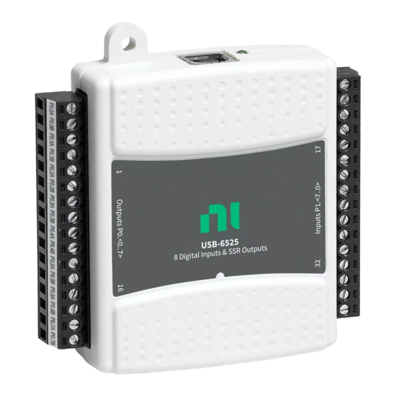
1 USB Cable Strain Relief
channel-to-channel isolated solid-state relay (SSR)
Figure 1. USB-6525 Top View
Advertisement
Table of Contents

Related Manuals for National Instruments 779640-01


Summary of Contents for National Instruments 779640-01
- Page 1 USER GUIDE AND SPECIFICATIONS NI USB-6525 This user guide describes how to use the National Instruments USB-6525 data acquisition (DAQ) device. Introduction The NI USB-6525 is a full-speed USB 2.0 device that provides eight ±60 VDC channel-to-channel isolated digital inputs (DI),...
-
Page 2: Installing Software
The NI-DAQmx CD contains example programs that you can use to get started programming with the USB-6525. Refer to the NI-DAQmx for USB Devices Getting Started Guide, that shipped with your device and is also accessible from Start»All Programs»National Instruments»NI-DAQ for more information. Note For information about non-Windows operating system support, refer to ni.com/... -
Page 3: Setting Up Hardware
1 Overlay Label with Pin Orientation Guides 3 Screw Terminal Blocks 2 Combicon Jack 4 Signal Labels Figure 4. Signal Label Application Diagram Connect the wiring to the appropriate screw terminals. © National Instruments Corporation USB-6525 User Guide and Specifications... - Page 4 I/O Connector The USB-6525 device ships with two detachable terminal blocks for digital signals. Each individual terminal accepts a wire gauge between 16 AWG–28 AWG. Table 1. Digital Terminal Assignments Module Terminal Signal Module Terminal Signal P0.0A P1.0+ P0.0B P1.0– P0.1A P1.1+ P0.1B...
-
Page 5: Signal Descriptions
The filter operates on the inputs from the optocouplers. The optocouplers turn on faster than they turn off, passing rising edges faster than falling © National Instruments Corporation USB-6525 User Guide and Specifications... - Page 6 edges. The optocouplers can therefore subtract up to 150 μs from a low pulse. Table 3 lists the pulse widths guaranteed to be passed and blocked. Table 3. NI 6525 Digital Filtering Pulse Width Passed Pulse Width Blocked Filter Interval Low Pulse High Pulse Low Pulse...
-
Page 7: Digital Filtering Example
After a change, you can read the input lines to determine the current line states. The maximum rate of change detection is determined by the software response time, which varies from system to system. © National Instruments Corporation USB-6525 User Guide and Specifications... -
Page 8: Change Detection Example
An overflow bit indicates that an additional rising or falling edge has been detected before the software could process the previous change. Refer to the software documentation for information about how to set up and implement the change detection. Change Detection Example Table 4 shows a change detection example for six bits of one port. -
Page 9: Watchdog Timer
To use MAX (recommended) to program the power-up states, select the device and click the Properties button. Refer to the software documentation for information about how to program the power-up states using NI-DAQ with LabVIEW or other National Instruments application development environments (ADEs). Watchdog Timer... - Page 10 Each channel has its own positive and negative terminals. The input range on the channels is –60 VDC to +60 VDC. Sensing DC Voltages The USB-6525 detects a wide range of DC signals, from TTL-like logic levels to DC power supply levels up to 60 V. Applying a DC voltage of at least 3.2 V across two input terminals registers logic high.
- Page 11 Limit flyback voltages at your inductive load by installing one of the following: • For DC loads—Install a flyback diode within 18 in. of the load. • For AC loads—Install a metal oxide varistor (MOV) rated for 30 V or slightly higher. © National Instruments Corporation USB-6525 User Guide and Specifications...
- Page 12 Figures 8 and 9 show examples of using an external flyback diode to protect DC inductive loads and an MOV to protect AC inductive loads, respectively. Flyback Diode for DC Inductive Loads P0.x A Inductive Load – P0.x B USB-6525 Figure 8.
-
Page 13: Event Counter
For more information about event timing requirements, refer to Specifications section. Refer to your software documentation for more information about counter programming techniques. © National Instruments Corporation USB-6525 User Guide and Specifications... -
Page 14: Specifications
Specifications The following specifications are typical at 25 °C, unless otherwise noted. Isolated Inputs Number of input channels.......8, ch-ch isolated Input voltage range .........–60 VDC to 60 VDC Level Input low voltage –60 VDC 1 VDC Input high voltage 3.2 VDC 60 VDC Input current ...........3.0 mA/channel max Minimum pulse-width... -
Page 15: Bus Interface
Torque for screw terminals ....0.22 – 0.25 N · m (2.0 – 2.2 lb · in.) Weight With connectors ......Approx. 87 g (3.1 oz) Without connectors ......Approx. 64 g (2.3 oz) © National Instruments Corporation USB-6525 User Guide and Specifications... -
Page 16: Hazardous Locations
Safety Standards This product meets the requirements of the following standards of safety for electrical equipment for measurement, control, and laboratory use: • IEC 61010-1, EN 61010-1 • UL 61010-1, CSA 61010-1 Note For UL and other safety certifications, refer to the product label or the Online Product Certification section. -
Page 17: Electromagnetic Compatibility
For additional environmental information, refer to the NI and the Environment Web page at . This page contains the ni.com/environment environmental regulations and directives with which NI complies, as well as other environmental information not included in this document. © National Instruments Corporation USB-6525 User Guide and Specifications... -
Page 18: Waste Electrical And Electronic Equipment (Weee)
Waste Electrical and Electronic Equipment (WEEE) EU Customers At the end of their life cycle, all products must be sent to a WEEE recycling center. For more information about WEEE recycling centers and National Instruments WEEE initiatives, visit ni.com/environment/weee.htm National Instruments... - Page 19 Working Voltage is the highest rms value of an AC or DC voltage that can occur across any particular insulation. MAINS is defined as a hazardous live electrical supply system that powers equipment. Suitably rated measuring circuits may be connected to the MAINS for measuring purposes. © National Instruments Corporation USB-6525 User Guide and Specifications...
-
Page 20: Where To Go For Support
Taiwan 886 02 2377 2222, Thailand 662 278 6777, Turkey 90 212 279 3031, United Kingdom 44 (0) 1635 523545 National Instruments, NI, ni.com, and LabVIEW are trademarks of National Instruments Corporation. Refer to the Terms of Use section on ni.com/legal for more information about National Instruments trademarks.
Need help?
Do you have a question about the 779640-01 and is the answer not in the manual?
Questions and answers