
Related Manuals for National Instruments USB-6525


Summary of Contents for National Instruments USB-6525
- Page 1 National Instruments USB-6525 Manual Get Pricing & Availability at ApexWaves.com Call Today: 1-800-915-6216 Email: sales@apexwaves.com https://www.apexwaves.com/modular-systems/national-instruments/dio-series/USB-6525...
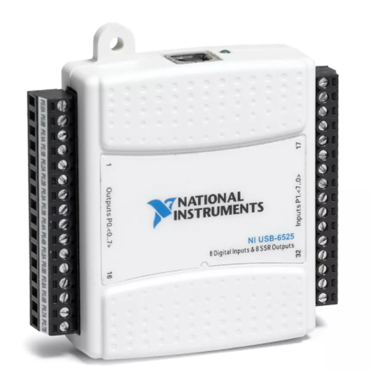
- Page 2 USER GUIDE AND SPECIFICATIONS NI USB-6525 This user guide describes how to use the National Instruments USB-6525 data acquisition (DAQ) device. Introduction The NI USB-6525 is a full-speed USB 2.0 device that provides eight ±60 VDC channel-to-channel isolated digital inputs (DI),...
-
Page 3: Installing Software
Figure 2. USB-6525 Back View Installing Software Software support for the USB-6525 for Windows 2000/XP is provided by NI-DAQmx. The NI-DAQmx CD contains example programs that you can use to get started programming with the USB-6525. Refer to the NI-DAQmx for USB Devices Getting Started Guide, that shipped with your device and is also accessible from Start»All Programs»National Instruments»NI-DAQ... -
Page 4: Setting Up Hardware
Install combicon screw terminal blocks by inserting them into the combicon jacks. Note The USB-6525 kit ships with signal labels. You can apply the signal labels on the screw terminal blocks for easy signal identification. Refer to Table 1 and Figure 4 for label orientation and affix provided signal labels to the screw terminal blocks. - Page 5 I/O Connector The USB-6525 device ships with two detachable terminal blocks for digital signals. Each individual terminal accepts a wire gauge between 16 AWG–28 AWG. Table 1. Digital Terminal Assignments Module Terminal Signal Module Terminal Signal P0.0A P1.0+ P0.0B P1.0–...
-
Page 6: Signal Descriptions
The filter operates on the inputs from the optocouplers. The optocouplers turn on faster than they turn off, passing rising edges faster than falling © National Instruments Corporation USB-6525 User Guide and Specifications... - Page 7 The filter clock is programmable and allows you to control how long a pulse must last to be recognized. The sample clock provides a fast sample rate to ensure that input pulses remain constant between filter clocks. The accuracy of the sample clock is ±1.5%. USB-6525 User Guide and Specifications ni.com...
-
Page 8: Digital Filtering Example
After a change, you can read the input lines to determine the current line states. The maximum rate of change detection is determined by the software response time, which varies from system to system. © National Instruments Corporation USB-6525 User Guide and Specifications... -
Page 9: Change Detection Example
You cannot read the state of any lines that are configured for change detection until the change detection interrupt occurs. USB-6525 User Guide and Specifications ni.com... -
Page 10: Programmable Power-Up Output States
Event Counter section for more information about the counter. Optically Isolated Inputs The USB-6525 provides eight channels of isolated digital inputs. These inputs consist of an optocoupler, a depletion-mode MOSFET-based current-limiting circuit, and Schottky diode. The accuracy of the sample clock is ±1.5%. -
Page 11: Sensing Dc Voltages
When the switch is open, no current flows through the load and no voltage is applied to the load or to the USB-6525 input. The digital logic of the USB-6525 then registers a logic low for the channel. When the switch is USB-6525 User Guide and Specifications ni.com... -
Page 12: Solid-State Relay (Ssr) Outputs
USB-6525 registers a logic high for the channel. Solid-State Relay (SSR) Outputs You can connect loads to the USB-6525. Connect the load to one of the leads of the power source. Connect either the P0.xA or the P0.xB terminal to the load and the other terminal to the other lead of the AC or DC power source. - Page 13 P0.x A Inductive Load – P0.x B USB-6525 Figure 8. Contact Protection for DC Inductive Loads MOV for AC Inductive Loads P0.xA Inductive Load P0.xB USB-6525 Figure 9. Contact Protection for AC Inductive Loads USB-6525 User Guide and Specifications ni.com...
-
Page 14: Using The Usb-6525 As A Ttl Output Device
Using the USB-6525 as a TTL Output Device Figure 10 shows a signal connection example for a TTL-level application with an external supply voltage of +5 V. To External +5 V Supply = 5 kΩ P0.x A P0.x B Isolated... -
Page 15: Specifications
Switching rate (90% duty cycle) ....5 operations per second Relay open time ........60 μs typ Relay close time........1.2 ms typ On resistance...........550 mΩ max Off state leakage ........0.6 μA typ Counter Number of counters ........1 (P1.7 can be configured as a counter) USB-6525 User Guide and Specifications ni.com... -
Page 16: Bus Interface
Torque for screw terminals ....0.22 – 0.25 N · m (2.0 – 2.2 lb · in.) Weight With connectors ......Approx. 87 g (3.1 oz) Without connectors ......Approx. 64 g (2.3 oz) © National Instruments Corporation USB-6525 User Guide and Specifications... -
Page 17: Hazardous Locations
Do not use this module for connection to signals or for measurements within Measurement Categories II, III, or IV. Hazardous Locations The USB-6525 is not certified for use in hazardous locations. Environmental The USB-6525 device is intended for indoor use only. -
Page 18: Electromagnetic Compatibility
For additional environmental information, refer to the NI and the Environment Web page at . This page contains the ni.com/environment environmental regulations and directives with which NI complies, as well as other environmental information not included in this document. © National Instruments Corporation USB-6525 User Guide and Specifications... -
Page 19: Waste Electrical And Electronic Equipment (Weee)
The following section contains important safety information that you must follow when installing and using the USB-6525. Do not operate the USB-6525 in a manner not specified in this document. Misuse of the device can result in a hazard. You can compromise the safety protection built into the device if the device is damaged in any way. - Page 20 Working Voltage is the highest rms value of an AC or DC voltage that can occur across any particular insulation. MAINS is defined as a hazardous live electrical supply system that powers equipment. Suitably rated measuring circuits may be connected to the MAINS for measuring purposes. © National Instruments Corporation USB-6525 User Guide and Specifications...
-
Page 21: Where To Go For Support
Taiwan 886 02 2377 2222, Thailand 662 278 6777, Turkey 90 212 279 3031, United Kingdom 44 (0) 1635 523545 National Instruments, NI, ni.com, and LabVIEW are trademarks of National Instruments Corporation. Refer to the Terms of Use section on ni.com/legal for more information about National Instruments trademarks.
Need help?
Do you have a question about the USB-6525 and is the answer not in the manual?
Questions and answers