Table of Contents
Advertisement
Quick Links
Advertisement
Table of Contents

Related Manuals for Pentair Autotrol 255 Logix 740-760


Summary of Contents for Pentair Autotrol 255 Logix 740-760
- Page 1 AUTOTROL 255 LOGIX 740-760 INSTALLER MANUAL WATER PURIFICATION...
-
Page 2: Table Of Contents
Installer Manual 255-LOGIX 740-760 - Table of content Table of content Generalities ......... . 6 1.1. - Page 3 Installer Manual 255-LOGIX 740-760 - Table of content Installation ......... . 23 5.1.
- Page 4 Installer Manual 255-LOGIX 740-760 - Table of content Commissioning ........45 7.1.
- Page 5 Installer Manual 255-LOGIX 740-760 - Table of content Spare parts ......... . 67 11.1.
-
Page 6: Generalities
23.05.2018 BRY/FLA tank assembly. 08.10.2019 General corrections. 1.3. Manufacturer identifier, product Manufacturer: Pentair International LLC Avenue de Sevelin 18 1004 Lausanne Switzerland Product: 255-LOGIX 740-760 1.4. Intended use The device is intended to be used for domestic applications only and it is purpose-built for water treatment. -
Page 7: Abbreviations Used
Installer Manual 255-LOGIX 740-760 - Generalities 1.5. Abbreviations used BLFC ................. Brine Line Flow Controller DF..................Down Flow DLFC ................. Drain Line Flow Controller Inj ..................Injector PN ..................Part Number QC..................Quick Connect Regen ................Regeneration SBV..................Safety Brine Valve TC .................. -
Page 8: Procedure For Technical Support
Pentair Quality System EMEA products benefit, under specific conditions, from a manufacturer warranty that may be invoked by Pentair’s direct customers. Users should contact the vendor of this product for applicable conditions and in case of a potential warranty claim. -
Page 9: Scan & Service Application
Installer Manual 255-LOGIX 740-760 - Generalities 1.10. Scan & Service application Scan & Service mobile application is the ideal support for the maintenance person in his daily business. A simple scan of an identification (ID) label (1) present on the valve with a smartphone gives an instantaneously access to all updated information related to the product, such as: •... -
Page 10: Safety
Installer Manual 255-LOGIX 740-760 - Safety Safety 2.1. Safety pictograms definition Caution Warning Warns of a risk of minor injury or major Warns against serious personal injury material damage to the device or and damage to health. environment. Danger Mandatory Warns against serious personal injury or Standard or measure to apply. -
Page 11: Hazards
Installer Manual 255-LOGIX 740-760 - Safety 2.3. Hazards All the safety and protection instructions contained in this document must be observed in order to avoid temporary or permanent injury, damage to property or environmental pollution. At the same time, any other legal regulations, accident prevention and environmental protection measures, as well as any recognized technical regulations relating to appropriate and risk-free methods of working which apply in the country and place of use of the device must be adhered to. -
Page 12: Hygiene Measures
Installer Manual 255-LOGIX 740-760 - Safety Assembly • Assemble only with components which are in accordance with DM 174 and ACS; • after installation and before use, perform one or more manual regenerations in order to clean the media bed. During such operations, do not use the water for human consumption. Perform a disinfection of the system in the case of installations for treatment of drinking water for human use. -
Page 13: Description
(0.8125") optional with extra insert Riser tube [length]............29 mm ± 3 mm (1⅛ ± ⅛") above top of tank Electrical Controller Operating Voltage ........... 12 VAC (requires use of Pentair Water supplied transformer) Input Supply Frequency............ 50 or 60 Hz (controller configuration dependent) Motor Input Voltage ............ -
Page 14: Performance Flow Rate Characteristics
Installer Manual 255-LOGIX 740-760 - Description 3.1.1. Performance flow rate characteristics The graph shows the pressure drop created by the valve itself at different flow rates. It makes it possible to predetermine the maximum flow rate going through the valve depending on the system settings (inlet pressure etc). -
Page 15: Outline Drawing
Installer Manual 255-LOGIX 740-760 - Description 3.2. Outline drawing Ref. MKT-IM-001 / C - 08.10.2019 15 / 76... -
Page 16: Description And Components Location
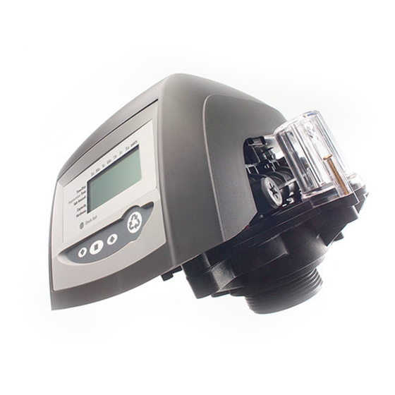
Installer Manual 255-LOGIX 740-760 - Description 3.3. Description and components location One-piece valve disc spring Injector and cap Optical sensor Control module mount Manifold connection LCD display BLFC / Refill controller Brine tank tube Check ball connection Air check Manual REGEN button UP button SET button DOWN button... -
Page 17: System Regeneration Cycle (8-Cycles Operation)
Installer Manual 255-LOGIX 740-760 - Description 3.4. System regeneration cycle (8-cycles operation) Service (downflow) — cycle C0 Untreated water is directed down through the resin bed and up through the riser tube. The hardness ions attach themselves to the resin and are removed from the raw water being exchanged on the resin beads towards sodium ions. - Page 18 Installer Manual 255-LOGIX 740-760 - Description SERVICE BACKWASH C1 and C6 Inlet Outlet Inlet Outlet Drain Valve Valve BRINE/SLOW RINSE REPRESSURIZE C2-C3 Inlet Outlet Inlet Outlet Drain Valve Valve From brine tank RAPID RINSE BRINE REFILL C5 and C7 Inlet Outlet Inlet Outlet...
-
Page 19: System Sizing
Installer Manual 255-LOGIX 740-760 - System sizing System sizing 4.1. Recommendations 4.1.1. Injector/DLFC/Refill flow controler-Valve configuration Backwash flow Vessel diameter Media volume Injector Flow Refill flow control control [In] control [gpm] [gpm] 5/10 E [yellow] 0.33 F [peach] 0.33 G [tan] 0.33 H [lt purple] 0.33... -
Page 20: Injector Flow Rates (Tables)
Installer Manual 255-LOGIX 740-760 - System sizing 4.3. Injector flow rates (tables) The following tables represent the injectors flow rate as a function of the inlet pressure for the different injector sizes. TOTAL BRINE DRAW RINSE Injector "F" (Peach) Injector "E" (Yellow) For 7"... - Page 21 Installer Manual 255-LOGIX 740-760 - System sizing TOTAL BRINE DRAW RINSE Injector "K" (Pink) Injector "J" (Light Blue) For 12" Tanks For 10" Tanks Inlet pressure [bar] Inlet pressure [bar] Injector "L" (Orange) For 13 " and 14" Tanks Inlet pressure [bar] Ref.
-
Page 22: Salt Amount Definition
Installer Manual 255-LOGIX 740-760 - System sizing 4.4. Salt amount definition 3 salt settings are available on 740 and 760 controls: Equivalent CaCO Settings Amount of brine used 45 [g L - (Low Salt) 30 [g/L] salt resin 120 [g S - (Standard Salt) 60.2 [g/L] salt... -
Page 23: Installation
Installer Manual 255-LOGIX 740-760 - Installation Installation 5.1. Safety notices for installation • Observe all warnings that appear in this manual; • only qualified and professional personnel are authorized to carry out installation work. 5.2. Installation environment 5.2.1. General • Use only brine salts designed for water softening. -
Page 24: Mechanical
Installer Manual 255-LOGIX 740-760 - Installation 5.2.3. Mechanical • Do not use petroleum-based lubricants such as vaseline, oils, or hydrocarbon-based lubricants. Use only 100% silicone lubricants; • all plastic connections should be hand tightened. PTFE (plumber’s tape) may be used on connections that do not use an O-ring seal. -
Page 25: Integration Constraints
Installer Manual 255-LOGIX 740-760 - Installation 5.3. Integration constraints Location of a water treatment system is important. The following conditions are required: • level platform or floor; • room to access equipment for maintenance and adding brine (salt) to tank; •... -
Page 26: Block Diagram And Configuration Example
Installer Manual 255-LOGIX 740-760 - Installation 5.4. Block diagram and configuration example Block diagram Pressure gauge Main inlet User’s line Check valve to prevent water harm Filter cartridge By-pass Pressure regulator Meter Suggested options Mixing device Can be integrated in the Drain line valve Brine line... -
Page 27: Valve Connection To Piping
Installer Manual 255-LOGIX 740-760 - Installation 5.5. Valve connection to piping The connections should be hand tightened using PTFE (plumber’s tape) on the threads if using the threaded connection type. In case of heat welding (metal type connection), the connections should not be made to the valve when soldering. - Page 28 • in any case, any failure caused by improper installation and/or piping connections may void the warranty of Pentair products; • in the same way, using lubricant* on the valve thread is not allowed and will void the warranty for the valve and tank.
-
Page 29: Connections (Electrical)
Installer Manual 255-LOGIX 740-760 - Installation 5.6. Connections (electrical) Lockout connection (764 only) Chlorine generator outlet (EU versions only) AC transformer input (low voltage) Main motor & optical sensor connection Sensor input for turbine 760/762 Dry contact signal input 740/742 Secondary valve motor control (764 only) 5.7. -
Page 30: Drain Line Connection
Installer Manual 255-LOGIX 740-760 - Installation Caution Do not solder pipes with lead-based solder. Caution Do not use tools to tighten plastic fittings. Over time, stress may break the connections. When the 256 bypass valve is used, only hand tighten the plastic nuts. Caution... -
Page 31: Overflow Line Connection
Installer Manual 255-LOGIX 740-760 - Installation Note Waste connections or the drain outlet shall be designed and constructed to provide connection to the sanitary waste system through an air-gap of 2 pipe diameters or 25.4 mm (1"), whichever is larger. Caution... -
Page 32: Brine Line Connection
Installer Manual 255-LOGIX 740-760 - Installation Overflow fitting Drain tubing Secure hose in place Air gap Drain Caution Floor drain is always recommended to avoid flooding in case of overflow. 5.10. Brine line connection The brine line from the tank connects to the valve. Make the connections and hand tighten. Be sure that the brine line is secure and free from air leaks. -
Page 33: Programming
Installer Manual 255-LOGIX 740-760 - Programming Programming 6.1. Display 1. Hourglass Displayed when the motor is running. The camshaft should be turning. 2. Cursor These cursors appear next to the item that is currently displayed. 3. Days of the week Displayed days of the week. - Page 34 Installer Manual 255-LOGIX 740-760 - Programming 11. "g/L" Indicates that the value entered/displayed for salt amount is in grams/ Liter of resin. 12. "KG" Indicates that the value entered/displayed is in kilograms or kilograins. 13. "x100" x100 multiplier for large values. Indicates that the value entered/displayed for salt amount is in pounds 14.
-
Page 35: Commands
Installer Manual 255-LOGIX 740-760 - Programming 6.2. Commands - Down arrow Scrolls down or decrement through a group of choices. Accepts a setting that normally becomes stored in memory. - Set Also used together with the arrow buttons to access special features. - Up arrow Scrolls up or increment through a group of choices. -
Page 36: Basic Programming
Installer Manual 255-LOGIX 740-760 - Programming 6.3. Basic programming Note Menus are displayed in a defined and incremental order. 6.3.1. Basic programming mode chart Default Units of Parameter description Range of values Notes value measure To choose a 3-cycle filter 5 - 80 / F Program system size None... -
Page 37: Program System Size
Installer Manual 255-LOGIX 740-760 - Programming 6.3.2. Program system size Set your input system size and your resin volume in liters. to scroll though resin volume choices. Choose the nearest volume to your actual system size. To choose a 3-cycle filter operation, press until an "F"... -
Page 38: Day Of Week
Installer Manual 255-LOGIX 740-760 - Programming 6.3.4. Day of week Set the current day of the week. Press → Arrow flashes. Select displayed day with Press to validate the selection and advance to the next parameter using 6.3.5. Regeneration time Set the time when regeneration will take place. -
Page 39: Calendar Override (760 On-Demand Controller Only)
Installer Manual 255-LOGIX 740-760 - Programming 6.3.7. Calendar override (760 on-demand controller only) Set number of days for calendar override on-demand controller. Press → Number of days flashes. Adjust displayed number with → Default time for calendar override: 0 day. →... -
Page 40: Estimated Capacity
Installer Manual 255-LOGIX 740-760 - Programming 6.3.9. Estimated capacity Note The system capacity is displayed in kilograms equivalent CaCO of hardness removed before a regeneration is necessary. Note Value is derived from the system’s resin volume input and salt amount input. Note... -
Page 41: Advanced Programming
Installer Manual 255-LOGIX 740-760 - Programming 6.4. Advanced programming Note Press and hold for 5 seconds to access advance programming. A "P" symbol is displayed on the bottom left of screen. The 740/760 features an advanced programming level that allows the installing dealer to make changes to the controller for more demanding applications. -
Page 42: Master Setting Reference Chart
Installer Manual 255-LOGIX 740-760 - Programming 6.4.1. Master setting reference chart Default Units of Parameter description Range of values Notes value measure 1:00 - 12:59 AM hour: Range depends on value Time of day 12:00 PM 0:00 - 23:59 PM minute selected for P10. -
Page 43: Cycle Time Programming
Installer Manual 255-LOGIX 740-760 - Programming 6.4.2. Cycle time programming Press and hold the for 5 seconds when the controller is not in regeneration to enter cycle time programming. → A small “C#” with a number will be displayed indicating the controller is in cycle time programming. -
Page 44: Diagnostic
Installer Manual 255-LOGIX 740-760 - Programming 6.4.3. Diagnostic To access diagnostic values, press and hold for 5 seconds to view the "H" levels. Diagnostic Description Unit Range Code Resin volume Day since last regeneration l/min 0 - 255 Current flow rate 0 - 177 Water used today (since time of regeneration) l/min... -
Page 45: Commissioning
Installer Manual 255-LOGIX 740-760 - Commissioning Commissioning Note This chapter is available for standard regeneration types. Contact your supplier if the actual regeneration is not standard and if you need assistance. 7.1. Water filling, draining and waterproofness inspection 7.1.1. Activating the softener After you have performed the previous initial programming steps, you will need to activate the softener. - Page 46 Installer Manual 255-LOGIX 740-760 - Commissioning 5. Add water to the brine tank (initial fill) (softener only). → With a bucket or hose, add approximately 15 liters (4 gallons) of water to the brine tank. If the tank has a salt platform in the bottom of the tank, add water until the water level is approximately 25 mm (1") above the platform.
-
Page 47: Additional Tips
Installer Manual 255-LOGIX 740-760 - Commissioning 8. If the water level is receding from the brine tank you can then advance the controller back to the treated water (C0) position by pressing simultaneously to advance the controller to the C0 position. 9. -
Page 48: Sodium Or Calcium Hypochlorite
Installer Manual 255-LOGIX 740-760 - Commissioning 7.2.2. Sodium or calcium hypochlorite These materials are satisfactory for use with polystyrene resins, synthetic gel zeolite, greensand and bentonites. 5.25% Sodium hypochlorite If stronger solutions are used, such as those sold for commercial laundries, adjust the dosage accordingly. -
Page 49: Operation
Installer Manual 255-LOGIX 740-760 - Operation Operation During a regeneration: • A "C#" is displayed to show the current cycle; • total regen time remaining is displayed on screen; • you can press and hold to show current cycle time remaining. 8.1. -
Page 50: To Advance Regeneration Cycles
Installer Manual 255-LOGIX 740-760 - Operation Double regeneration After an immediate regeneration has begun, press again to plan a second manual regeneration. → A flashing "x2" symbol indicates the second regeneration will start at the programmed delayed regeneration time. Immediate double regeneration Press and hold to start the second regeneration immediately following the current regeneration. -
Page 51: Maintenance
Installer Manual 255-LOGIX 740-760 - Maintenance Maintenance Mandatory Cleaning and maintenance shall take place at regular intervals in order to guarantee the proper functioning of the complete system, and be documented in the Maintenance chapter in the User Guide document. Mandatory... -
Page 52: Regeneration Test
Installer Manual 255-LOGIX 740-760 - Maintenance 9.1.3. Regeneration test 1. Check condition of brine tank and any associated equipment. 2. Check salt level in brine tank. 3. Initiate regeneration test. → Check brine draw during brine draw stage, observe aircheck ball and make sure or proper function. - Page 53 Installer Manual 255-LOGIX 740-760 - Maintenance Items 1 year 2 year 3 year 4 year 5 year Motor, motor cable and Check Check Check Check Replace optical sensor harness Optical sensor Check Check Check Check Replace Inlet Hardness Check Check Check Check Check...
-
Page 54: Recommendations
Installer Manual 255-LOGIX 740-760 - Maintenance 9.3. Recommendations 9.3.1. Use original spare parts Caution To ensure correct operation and safety of the device, only use original spare parts and accessories recommended by the manufacturer. Parts to keep in stock for potential replacements are motor and optical sensor, controller, transformer, injectors, flapper kit, O-ring kit, refill and DLFC. -
Page 55: Injector Cleaning
Installer Manual 255-LOGIX 740-760 - Maintenance 9.4.2. Injector cleaning Operation Using a Torx key, unscrew and remove the injector cap (4). Caution Take care not to damage the injector (5). Using pliers, gently extract the injector (5) from valve body. Clean the injector (5) using compressed air, a soft brush or possibly a pin. -
Page 56: Injector Screen Cap Cleaning
Installer Manual 255-LOGIX 740-760 - Maintenance 9.4.4. Injector screen cap cleaning Operation Using a Torx key, unscrew and extract the injector screen cap (4). Unclip the white plastic basket (5) and clean it with a soft brush. Use of descaling agent such as white vinegar might be required in case of impurities on the plastic basket (5). -
Page 57: Air Check Valve Cleaning
Installer Manual 255-LOGIX 740-760 - Maintenance 9.4.6. Air check valve cleaning Operation Unscrew brine pipe (5). Using a Phillips screwdriver, loosen air check cap screw (2) (2x). Let the 2 screws (2) on the cap (4). Remove the cap (4). Clean the air check ball (3) and groove (1) using a soft cloth or a soft brush. -
Page 58: Valve From Tank Disassembly
Installer Manual 255-LOGIX 740-760 - Maintenance 9.4.7. Valve from tank disassembly Operation Tip Depending on the maintenance required, it may be useful to disassemble the valve from the tank in order to have easier access. Unlock the cover (1) from the slide clips (2) (one on each side of the valve). Lift the cover (1). -
Page 59: Motor And Camshaft Replacement
Installer Manual 255-LOGIX 740-760 - Maintenance 9.4.8. Motor and camshaft replacement Operation Remove the white locking pin (2) securing the motor (3). Turn the motor (3) counter clockwise and slide it out of its position. Slide the camshaft (1) backwards until it is released from its mounting boss, then lift it up. Ref. -
Page 60: Optical Sensor And Controller Replacement
Installer Manual 255-LOGIX 740-760 - Maintenance 9.4.9. Optical sensor and controller replacement Operation Note To remove the optical sensor, you first have to disassemble the camshaft. See “Motor and camshaft replacement”, page 59. Caution Take care with sharp edges. The optical sensor (2) is clipped on the front edge, gently press on the clips to release the optical sensor (2) from its location. -
Page 61: Top Plate And Disc Valve Replacement
Installer Manual 255-LOGIX 740-760 - Maintenance 9.4.10. Top plate and disc valve replacement Operation Caution Take care with sharp edges. Use of protective glove is highly recommended to remove the spring (3). Using a flat screwdriver, release the flapper springs (2) one by one and then remove the spring (3). -
Page 62: Valve On Tank Assembly
Installer Manual 255-LOGIX 740-760 - Maintenance 9.4.11. Valve on tank assembly Operation Lubricate the seals with approved silicone grease. Spin the valve (1) onto the tank (2), ensuring the threads are not cross-threaded. Rotate the valve (1) clockwise and freely, without using force until it comes to a stop. Note... -
Page 63: Troubleshooting
Installer Manual 255-LOGIX 740-760 - Troubleshooting Troubleshooting Err. code Cause Reset and recovery Controller power has been connected Reset controller. ERR 1 and the controller is not sure of the See 6.4.4. Resetting the controller, operating status. page 44. Disconnect and reconnect the power. Controller power does not match 50 or If problem is not solved, obtain an ERR 2... - Page 64 Installer Manual 255-LOGIX 740-760 - Troubleshooting Issue Cause Reset and recovery - - : - - Power failure occurred. Press to reset the time. Remove brine controller to clean ball Uncontrolled brine refill flow rate. and seat. Brine tank Check all connections in brine line for Air leak in brine line to air check.
- Page 65 Installer Manual 255-LOGIX 740-760 - Troubleshooting Issue Cause Reset and recovery Set pump to maintain 1.4 bar at Low water pressure. softener. Restricted drain line. Change drain to remove restriction. Valve will not draw Injector plugged. Clean injector and screen. brine.
- Page 66 Installer Manual 255-LOGIX 740-760 - Troubleshooting Issue Cause Reset and recovery Control brine dosage set and repeat Improper regeneration. regeneration. Set P6 to proper level. Incorrect brine setting. See 6.3.8. Amount of brine used per regeneration, page 39. Run out of Incorrect hardness or capacity Set to correct values.
-
Page 67: Spare Parts
Installer Manual 255-LOGIX 740-760 - Spare parts Spare parts 11.1. Valve parts list Ref. MKT-IM-001 / C - 08.10.2019 67 / 76... - Page 68 Installer Manual 255-LOGIX 740-760 - Spare parts Assembly Item Part number Description quantity 1244650 255 valve assembly, without flow controls 1033784 255 tank adapter new style 1010154 O-ring EP 1232370 O-ring EP 1235340 Top plate, 255 valve, 700/860 series controller 1235341 Spring, one-piece, 255 valve 1236246...
- Page 69 Installer Manual 255-LOGIX 740-760 - Spare parts Assembly Item Part number Description quantity Drain control assembly with o-ring 1000208 N°6 1000209 No.7 (1.2 gpm; 4.5 Lpm) 1000210 No.8 (1.6 gpm; 6.1 Lpm) 1000211 No.9 (2.0 gpm; 7.6 Lpm) 1000212 No.10 (2.5 gpm; 9.5 Lpm) 1000213 No.12 (3.5 gpm;...
-
Page 70: Options And Special Kits
Installer Manual 255-LOGIX 740-760 - Spare parts 11.2. Options and special kits 740/760 Controller Assembly Item Part number Description quantity Electronics modules/controllers Logix 740 controller - picto diode/picto without diode/picto 1242147 filter Logix 760 controller - picto diode/picto without diode/picto 1242165 filter Transformer... - Page 71 Installer Manual 255-LOGIX 740-760 - Spare parts Meter adapter Assembly Item Part number Description quantity 1032350 Meter adapter kit 1040524 Piping boss/meter install kit 1234259 Male plastic piping boss 1" BSP + int. turbine 1234260 Male plastic piping boss 3/4" BSP + int. turbine * Not shown Ref.
- Page 72 Installer Manual 255-LOGIX 740-760 - Spare parts Piping boss (manifold) Assembly Item Part number Description quantity 3023761 Piping boss 3/4" BSPT stainless steel 3/8" BSPT drain 3023747 Piping boss 1" BSPT stainless steel 1/2" BSPT drain 1040283 Piping boss 3/4" BSPT Noryl 1/2" BSPT drain 1040524 Piping boss/meter install kit 3028275...
- Page 73 Installer Manual 255-LOGIX 740-760 - Spare parts Bypass & connections Assembly Item Part number Description quantity 1040769 Bypass body assy (includes bypass installation kit) 1040524 Bypass installation kit 1034302 Bypass repair kit (rotor seals & clips) 3028264 Drain elbow for bypass 256 3023824 3/4"...
- Page 74 Installer Manual 255-LOGIX 740-760 - Spare parts Valve installation kits Part Assembly Item Description number quantity Kit-255/1 3029815 Comprises MS-4564PO; CC-D1203; MS-RI3460; AV090 E01240 Air check elbow (CA40) 1/4" FNPT- 3/8" T 4564PO 1009116 Upper screen 3028263 Riser tube 1.050" RI3460 AV090 3028267...
-
Page 75: Disposal
This will help to reduce the impact on the environment, health, safety and help to promote recycling. Pentair does not collect used product for recycling. Contact your local recycling center for more information. - Page 76 www.pentairaquaeurope.com...
Need help?
Do you have a question about the Autotrol 255 Logix 740-760 and is the answer not in the manual?
Questions and answers
How much water should be in the brine tank at the end of the c-8 cycle is that amount of water enough for the next regeneration?
The recommended water level in the brine tank for the Pentair Logix 740-760 at the end of the C8 (Refill) cycle is enough to allow the chlorine solution to be carried into the softener. This amount is sufficient for the next regeneration.
This answer is automatically generated