Table of Contents
Advertisement
Quick Links
Advertisement
Table of Contents

Related Manuals for Mirion Technologies LDM 320


Summary of Contents for Mirion Technologies LDM 320
- Page 1 Dosimetry Hands-Free Reader LDM 320 User's Manual 150532EN-C...
- Page 2 LDM 320 Revision Log Revision Log Rev. Date Verified by Approved by Origin and description of Revised pages revision — — — Not issued — 16/02/2012 Perez J Salle JL. Translation of the French version — 2012–06 Perez J Perez J Salle JL.
-
Page 3: Table Of Contents
3.1.1. Installation 3.2. Installation of USB Driver 3.2.1. Checking the LDM 320 Driver Installation 3.2.2. Installation of LDM 320 for Windows XP 3.2.3. Installation of LDM 320 for Windows Seven Operation 4.1. Setting Up the LDM 320D 4.2. Setting Up the LDM 320W 4.2.1. - Page 4 LDM 320 Table of Contents Certificate 150532EN-C Publication, traduction et reproduction totales ou partielles de ce document sont rigoureusement interdites, sauf autorisation écrite de nos services. The publication, translation or reproduction, either partly or wholly, of this document is not allowed without our written consent. Format 112175C.
-
Page 5: Introduction
LDM 320 Introduction Introduction 1.1. Related Documents and Product References Designation Reference Mounting Assembly LDM 320D 147636 Mounting Assembly LDM 320W 150518 LDM 320D 150534 LDM 320W 150517 Note: The LDM 320S (ref 149119) was designed specifically to operate in a strong magnetic background. -
Page 6: Description
(DOSICARE, DOSISERV and SENTINEL or configuration software (such as DMCUser)) to communicate with DMC 2000, DMC 3000 and SOR dosimeters. The LDM 320 is connected to a USB port of a PC. It is available in two versions: Desk version (LDM 320D):... -
Page 7: General Reader Operation
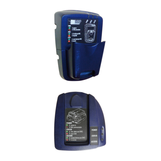
LDM 320 Description Wall mount version (LDM 320W): Figure 2 - LDM 320W 2.2. General Reader Operation The dosimeter reader is connected to a "host" PC through a USB link. Users operate the reader by computer via a USB cord. Most commands are intended for communication with a dosimeter present in the reader coverage area. -
Page 8: Ldm 320 Block Diagram
Description LDM 320 2.3. LDM 320 Block Diagram Figure 3 - Block Diagram 2.4. Reader Operating Modes The reader has several operating modes. Switching from one mode to another is done via computer. Upon power-on, the reader starts in the mode indicated by the associated configuration parameter. -
Page 9: Normal Operating Mode
LDM 320 Description 2.4.1. Normal Operating Mode This is the reader operational functioning mode. In this mode the reader operates as a slave to the PC: It retrieves the PC commands. It searches for dosimeters. It runs the commands (reading or writing dosimeter information or parameters). -
Page 10: Installation, Connection And Start-Up
(f = 125 kHz: video terminals, power supplies, rotary machines, etc.). Install readers in accordance with §4 recommendations. To install and start up the LDM 320, take the following steps: Install the software on the PC. Connect the reader to the PC. -
Page 11: Installation Of Usb Driver
Installation of USB Driver Some software programs such as DMCUser automatically install the USB driver specific to the LDM 320 readers. In the event of malfunction (hardware type not detected), the driver can be checked for correct installation by using the instructions below. -
Page 12: Checking The Ldm 320 Driver Installation
Checking the LDM 320 Driver Installation In order to check this driver for correct installation, follow the instructions below: Connect the LDM 320 reader to the computer USB port once the driver is installed. Using Windows, select the "Workstation" and right-click with the mouse. -
Page 13: Installation Of Ldm 320 For Windows Xp
Once the file is recovered, create a folder, and uncompress the compressed file into this folder. Connect the LDM 320 to a USB port. The computer will recognize a new device: 150532EN-C Publication, traduction et reproduction totales ou partielles de ce document sont rigoureusement interdites, sauf autorisation écrite de nos services. - Page 14 Installation, Connection and Start-up LDM 320 Click "Next" and indicate the access path to the uncompressed folder. 150532EN-C Publication, traduction et reproduction totales ou partielles de ce document sont rigoureusement interdites, sauf autorisation écrite de nos services. The publication, translation or reproduction, either partly or wholly, of this document is not allowed without our written consent. Format 112175C.
- Page 15 Once this operation is completed, the following screen will appear: Once the installation is complete, the computer will again detect a new "USB Serial Port" device. The LDM 320 is ready for use when the last screen indicates that the installation is completed. 150532EN-C Publication, traduction et reproduction totales ou partielles de ce document sont rigoureusement interdites, sauf autorisation écrite de nos services.
-
Page 16: Installation Of Ldm 320 For Windows Seven
Once the file is recovered uncompress the file into a folder. Connect the LDM 320 to a USB port. The computer will recognize a new device. Note: If Windows does not self start any installation procedure, open the Device Manager and apply the following procedure to install the driver. - Page 17 The port A driver is successfully installed. Once the port A driver is installed, repeat the same procedure for port B. The LDM 320 is ready for use. 150532EN-C Publication, traduction et reproduction totales ou partielles de ce document sont rigoureusement interdites, sauf autorisation écrite de nos services.
- Page 18 Installation, Connection and Start-up LDM 320 150532EN-C Publication, traduction et reproduction totales ou partielles de ce document sont rigoureusement interdites, sauf autorisation écrite de nos services. The publication, translation or reproduction, either partly or wholly, of this document is not allowed without our written consent. Format 112175C.
-
Page 19: Operation
LDM 320 Operation Operation 4.1. Setting Up the LDM 320D It is recommended to place the dosimeter on the reader, in the notch provided for this purpose, as represented below: During the exchanges between the reader and dosimeter, move other dosimeters at least 30 cm away from the reader. -
Page 20: Setting Up The Ldm 320W
Operation LDM 320 4.2. Setting Up the LDM 320W The LDM 320W readers feature a sleeve designed to accommodate the following dosimeters: DMC 2000 DMC 3000 SOR/R SOR/T IPAM-Tx, complete with dosimeter Figure 7 - DMC 3000 with and iPAM-Tx 4.2.1. -
Page 21: Installing A Dosimeter Rack
LDM 320 Operation 4.2.2. Installing a Dosimeter Rack It is recommended to install DMC racks a minimum of 50 cm away from any LDM 320 readers. Figure 9 - Readers and Dosimeter Rack 150532EN-C Publication, traduction et reproduction totales ou partielles de ce document sont rigoureusement interdites, sauf autorisation écrite de nos services. -
Page 22: Operating Significance Of The Lights
Operating significance of the lights The reader has no stand-alone function; it must be used connected to a PC using software provided by Mirion Technologies (MGPI). Three bicolor LEDs inform users about the status of exchange sequences with the dosimeter. -
Page 23: Maintenance
LDM 320 Maintenance Maintenance 5.1. Failure Analysis Symptoms Analysis Action Verify that the reader is Start again after checking. powered. Verify good connection with No communication with the the USB cable. Verify the proper Configure the port. If the fault configuration of the PC port. - Page 24 Maintenance LDM 320 Once the reader is disconnected, follow the procedure below: Remove the four side attaching screws and recover the washers (1). Once separated, remove the reader without applying excessive force to the cord. Remove the four screws and recover the washers (2).
-
Page 25: Characteristics
LDM 320 Characteristics Characteristics 6.1. Physical Characteristics 6.1.1. LDM 320D Length: 109 mm Width: 100 mm Depth: 29 mm Weight: 150 grams PC to reader cable length: 6.1.2. LDM 320W Length: 157 mm Width: 99 mm Depth: 75 mm Weight: 400 grams 6.2. -
Page 26: Environmental Conditions
Characteristics LDM 320 6.3. Environmental Conditions Operating Temperature: 0 to +50°C Storage Temperature: -10°C to +60°C Relative humidity (without condensation): IP Indice LDM 320D: IP52 IP Indice LDM 320W: IP30 6.4. USB Link 150532EN-C Publication, traduction et reproduction totales ou partielles de ce document sont rigoureusement interdites, sauf autorisation écrite de nos services. -
Page 27: Extension Connector
LDM 320 Characteristics Five-pin contact connector. J1 Pin No. Description Vbus (red) D- (white) D+ (green) GND (black) GND (Cable shielding) 6.5. Extension Connector Digital Outputs and Inputs can be controlled by the software: DMCUser. See user’s manual of this software for details. - Page 28 Characteristics LDM 320 J4 Pin No. Description INPUT Digital Input 5 Spare for ext. pwr sply Spare for RX-LDM Spare for RX-LDM Spare for analog input 1 Spare for analog input 2 Spare for external antenna (PWR4A) Spare for external antenna (PWR4B) 150532EN-C Publication, traduction et reproduction totales ou partielles de ce document sont rigoureusement interdites, sauf autorisation écrite de nos services.
-
Page 29: Spare Parts And Accessories
LDM 320 Spare Parts and Accessories Spare Parts and Accessories 7.1. Spare Parts LDM 320D Designation Reference USB cable 127684–SAV LDM 320W Designation Reference Case (Body + sleeve) 153367–SAV USB cable 127684–SAV 150532EN-C Publication, traduction et reproduction totales ou partielles de ce document sont rigoureusement interdites, sauf autorisation écrite de nos services. -
Page 30: Glossary
Glossary LDM 320 Glossary AGC: Automatic Gain Control DIO : Digital Input Output GND : Ground LED: Light Emitting Diode PC : Personal Computer 150532EN-C Publication, traduction et reproduction totales ou partielles de ce document sont rigoureusement interdites, sauf autorisation écrite de nos services. - Page 31 LDM 320 Certificate Certificate 150532EN-C Publication, traduction et reproduction totales ou partielles de ce document sont rigoureusement interdites, sauf autorisation écrite de nos services. The publication, translation or reproduction, either partly or wholly, of this document is not allowed without our written consent. Format 112175C.
- Page 32 Tel +49 (0) 89 515 13 0 Fax +49 (0) 89 515 13 169 www.mirion.com Due to evolutions in standards and equipment, the information provided is subject to change without notice. Please contact us for confirmation. Published by Mirion Technologies Format 112175D 150532EN-C...
Need help?
Do you have a question about the LDM 320 and is the answer not in the manual?
Questions and answers