Table of Contents
Advertisement
Quick Links
Advertisement
Table of Contents

Related Manuals for Mirion Technologies 2040


Summary of Contents for Mirion Technologies 2040
- Page 1 Model 2040 Coincidence Analyzer Manual Type 9231715B...
- Page 2 Copyright 2016, Mirion Technologies (Canberra), Inc . All rights reserved. The material in this document, including all information, pictures, graphics and text, is the property of Mirion Technologies (Canberra), Inc. and is protected by U.S. copyright laws and international copyright conventions.
-
Page 3: Table Of Contents
Input .............................. 13 Output ............................13 Controls ............................13 Performance ..........................13 Connectors ............................ 13 Physical............................13 Environmental ..........................14 B. Installation Considerations ............15 C. FCC Notice ................... 16 Model 2040 Coincidence Analyzer User's Manual - Not released – 9231715B... - Page 4 Product complies with appropriate current EU directives (Low Voltage & EMC). Product complies with appropriate current FCC /UL /CSA 61010-1 directives (Low Volatge & EMC). Manufacturer’s Address Mirion Technologies (Canberra), Inc. 800 Research Parkway Meriden, CT 06450 USA 2040 Coincidence Analyzer User's Manual - 9231715B...
-
Page 5: Introduction
LogicShaper and Delay may also be used as inputs to the 2040. The 2040 output pulse is a NIM logic pulse, and is produced when all switch-selected input conditions are met. For example, if A and B and ANTI inputs are IN, pulses must be present at A and B and not at ANTI, with the leading edges of A and B within the resolving time of the unit. -
Page 6: Applications
Model 2043 Time Analyzer shown in Figure 4. The 2040 coincidence would be used with the RANGE switch set to 0.1 - 1 μsec. Care must be used in the arrangement shown to set the relative delays properly, which is done by adjusting 2015A amplifier time constants, 2043 output delay, and 1457 de - lay amp time constants. -
Page 7: Controls And Connectors
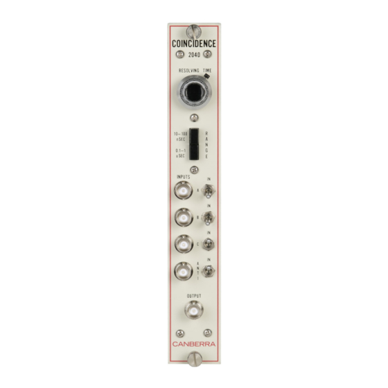
Front and Rear Panels 2. Controls and Connectors Front and Rear Panels This is a brief description of the 2040’s front and rear panel connectors. For more detailed information, refer to Appendix A, Specifications. Resolving Time Control This potentiometer selects resolving times within the range set by the RANGE switch. -
Page 8: Operations
Setup 1. Insert the Model 2040 Coincidence Analyzer module in an AEC compatible bin such as the Canberra Model 2000. 2. For coincidence operation, connect input signals, which meet the conditions detailed in the Inputs section of Appendix A, Specifications, to BNC connectors A and B. - Page 9 RESOLVING TIME set on the RESOLVING TIME control. Vary the delay and RESOLVING TIME controls and check them at different settings. Refer to Figure 4-2 for a typical linearity/accuracy curve of actual resolving time vs. indicated time. 2040 Coincidence Analyzer User's Manual - 9231715B...
- Page 10 Chapter 3 Operations 6. Set all IN switches at their off position (down). Note that the OUTPUT signal disappears. Figure 4-2 Dial Resolving Time vs. Actual Resolving Time Model 2040 Coincidence Analyzer User's Manual - Not released – 9231715B...
-
Page 11: Anti-Coincidence
A, B, or C occur in coincidence with the signal at the ANTI connector. 8. Repeat Step 7 utilizing other coincidence inputs. The following truth table will be obtained when operating the Model 2040 Coincidence Analyzer: Input Signal ANTI OUTPUT Note: It is assumed that a “0”... -
Page 12: Circuit Description
Analyzer. A functional schematic and/or block diagram of the Model 2040 can be ordered from Canberra. Each input to the Model 2040 has a differentiator and a one-shot associated with it. The differentiator detects the leading edge of the input pulse and generates a negative spike to trigger the one-shot. - Page 13 Anti-Coincidence 2040 Coincidence Analyzer User's Manual - 9231715B...
- Page 14 Chapter 4 Circuit Description Model 2040 Coincidence Analyzer User's Manual - Not released – 9231715B...
- Page 15 Anti-Coincidence 2040 Coincidence Analyzer User's Manual - 9231715B...
- Page 16 Chapter 4 Circuit Description Model 2040 Coincidence Analyzer User's Manual - Not released – 9231715B...
-
Page 17: Specifications
-12 V dc -12 mA Physical SIZE – Standard single-width NIM module 3.43 cm x 22.12 cm (1.35 x 8.71 in.) per DOE/ER-0457T. NET WEIGHT – 0.9 kg (2.0 lb). SHIPPING WEIGHT – 1.8 kg (4.0 lb). 2040 Coincidence Analyzer User's Manual - 9231715B... -
Page 18: Environmental
OPERATING TEMPERATURE – 0 to 50 °C. OPERATING HUMIDITY – 0 to 80% relative, non-condensing. Meets the environmental conditions specified by EN 61010, Installation Category I, Pollution Degree 2. Model 2040 Coincidence Analyzer User's Manual - Not released – 9231715B... -
Page 19: Installation Considerations
Any maintenance should be performed by a qualified Mirion Technologies (Canberra) service representative. Operating Protection Impairment Mirion Technologies (Canberra) is not liable for any operational malfunctions or personal injuries due to mishandling or unauthorized repair and maintenance not detailed in this manual. -
Page 20: Fcc Notice
Operation of this equipment in a residential area is likely to cause harmful interference in which case the user will be required to correct the interference at his own expense. Model 2040 Coincidence Analyzer User's Manual - Not released – 9231715B... - Page 21 Request for Circuit Information The Schematics and Block Diagrams may be available for this unit directly from Mirion Technologies (Canberra). Request can be made by calling, faxing, or emailing: Training and Technical Services Department Mirion Technologies (Canberra), Inc 800 Research Parkway, Meriden, CT 06450 Telephone: (800) 255-6370FAX: (203) 639-2067 Email: techsupport@canberra.com...
- Page 22 Notes...
- Page 23 _____________________________________________________ Warranty Mirion Technologies (Canberra) Inc. (we, us, our) warrants to the customer (you, your) that for a period of ninety (90) days from the date of shipment, software provided by us in connection with equipment manufactured by us shall operate in accordance with applicable specifications when used with equipment manufactured by us and that the media on which the software is provided shall be free from defects.
Need help?
Do you have a question about the 2040 and is the answer not in the manual?
Questions and answers