Table of Contents
Advertisement
Quick Links
Advertisement
Table of Contents

Related Manuals for Mirion Technologies Lynx II DSA


Summary of Contents for Mirion Technologies Lynx II DSA
- Page 1 Lynx Digital Signal Analyzer User's Manual 7096089...
- Page 2 The material in this document, including all information, pictures, graphics and text, is the property of Mirion Technologies, Inc. and is protected by U.S. copyright laws and international copyright conventions. Mirion Technologies, Inc. expressly grants the purchaser of this product the right to copy any material in this document for the purchaser’s own use,...
-
Page 3: Table Of Contents
The Lynx II DSA .......................... 25 Rack-Mount Option ......................... 26 Genie 2000 Analysis Software ..................... 26 Lynx II and MID Files ......................27 Editing an MCA's Settings ....................... 27 Editing the Definition ....................... 27 Lynx II DSA User's Manual – 7096089... - Page 4 Basic Detector Setup Using Lynx II ..................63 Communicating with Lynx II ....................... 65 Lynx Access – Default Settings ....................65 Universal Plug and Play ......................66 Communication Interfaces ....................... 67 Lynx II Setup for Administrators and Users................. 67 Lynx II DSA User's Manual - 7096089...
- Page 5 Print Spectrum ........................130 Security ..........................131 Backup and Restore........................ 132 Lock/Unlock ........................... 134 Release Notes ......................... 134 About Application ........................134 Reboot ............................ 134 A. Specifications ................135 Acquisition Device Input ......................135 Lynx II DSA User's Manual – 7096089...
- Page 6 Pileup Rejection With a Live Source ..................166 Live Time Correction With a Live Source ................. 168 PUR Guard ..........................170 PUR Guard Setup ........................171 PUR Guard Adjustment Using a Live Spectrum ..............172 Lynx II DSA User's Manual - 7096089...
- Page 7 Centroid ..........................192 FWHM and FWTM........................ 193 Area ............................193 Area Uncertainty ........................196 J. Installation Consideration ............198 K. FCC Notice ................. 199 L. Disposing of This Equipment ............ 200 Index ....................201 Lynx II DSA User's Manual – 7096089...
- Page 8 This device has been evaluated for the purpose of use in a work environment. If it is used in a home environment, there is a risk of interference with radio waves. Manufacturer's Address Mirion Technologies (Canberra), Inc. 800 Research Parkway Meriden, CT. 06450 USA Lynx II DSA User's Manual - 7096089...
-
Page 9: Preface
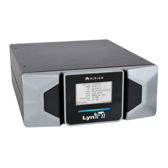
This User's Manual is intended for the readers who will use the Lynx II in their facility to acquire Figure 1 Front View of Lynx II DSA spectroscopic data; the installer or technician who will initially set up the system with other measurement and network equipment;... - Page 10 Notes viii Lynx II DSA User's Manual - 7096089...
-
Page 11: Introduction
This manual describes the capabilities of the Lynx II DSA and its Web-browser-based control software. Setup and interaction with the Genie 2000 software are reviewed, as it relates to the Lynx II DSA. System setup details for the Lynx II system are provided, and User instructions for data acquisitions are also described. - Page 12 The Lynx II User’s Manual is supplied as a PDF file on the Lynx II CD and also avalaible for download from www.mirion.com. Note: CDs are only distributed upon request. All contents of CD will be available on Mirion’s website. Lynx II DSA User's Manual - 7096089...
-
Page 13: Key Features
• Flexible form factor: for Standalone Desktop use; or rack-mount – one Lynx II unit, or two Lynx II units side by side, may be rack-mounted in 2U of a standard 19 inch electronics cabinet using the optional rack-mount kit. Lynx II DSA User's Manual – 7096089... -
Page 14: Abbreviations And Acronyms
Universal Serial Bus RNDIS: Remote Network Driver Interface Specification UPnP: Universal Plug and Play URL: Uniform Resource Locator, also referred to as a Web Address UTP: Unshielded Twisted Pair in reference to Ethernet cables Lynx II DSA User's Manual - 7096089... -
Page 15: Acquisition Modes And Acquisition Units
Input #2 must be set for MCS mode. Acquisition can be directed into either of two memory groups. The memory groups are identical in size. Each group can store the spectrum data and the elapsed sweeps independent of the other group Lynx II DSA User's Manual – 7096089... - Page 16 If data is not requested and buffers run out, eventually new data will be lost. If using List or time-stamped List mode through a custom application, please see the important note in Using the Programming Libraries on page 7. Lynx II DSA User's Manual - 7096089...
-
Page 17: Using Programming Libraries
This removed data will then no longer be available to the programming library. Ask your local representative for more information about the Programming Libraries, if required. Lynx II DSA User's Manual – 7096089... -
Page 18: Getting Started
Chapter 2 Getting Started 2. Getting Started The Lynx II DSA can be accessed from a computer through any of the following ways: • Through Mirion’s Genie Spectroscopy Analysis suite. Please refer to the Genie 2000 Analysis Software on page 26 for more information on using Genie. - Page 19 By default, the factory settings disable the “Login required” setting. If requested, please enter the user name and password. The factory default name is administrator and the default password is password. Lynx II DSA User's Manual – 7096089...
-
Page 20: Introduction To The Lynx Ii Web Client Interface
• The Maintenance option in the Navigator view provides access to maintenance features such as MCA information, errors/diagnostics, firmware updates, etc. • Acquisition control is through the Acquisition Panel. Figure 4: Acquisition Panel Lynx II DSA User's Manual - 7096089... -
Page 21: Accessing The Lynx Ii System
USB. Please refer to Lynx II Access – Default Settings on page 65 for additional information on each connection method using factory settings, with guidance on how to set up the communication adapter on the computer side. Lynx II DSA User's Manual – 7096089... - Page 22 DHCP server. Click the Save button to save all changes. If the Network Settings have changed, communication to your Lynx II will likely stop until your browser is redirected to the new settings. Lynx II DSA User's Manual - 7096089...
- Page 23 Acquisition | Coincidence to set coincidence parameters, or Acquisition | External Control to set external start/stop control parameters. The Acquisition Mode for Input 1 can be set to PHA, DLFC, MSS, LIST, or TLIST modes. Lynx II DSA User's Manual – 7096089...
-
Page 24: Sample Energy Calibration
This option displays the energy and FWHM calibration coefficients only. These coefficients are used to convert from channel to energy in the spectral plot. Proper calibration can be performed using Mirion’s software like Genie 2000, Apex, or ProSpect. Lynx II DSA User's Manual - 7096089... -
Page 25: Controls And Connectors
Front Panel LCD Screen The front panel LCD screen displays the instrument status and activity of the Lynx II unit. Lynx II DSA is powered up and turned on the Power LED Bar on the front panel is a steady blue. - Page 26 • Simultaneous PHS/MCS, “PHA MCS”. Note this is displayed when both MCS and PHA inputs are acquiring data. • “MSS”, if the state is MSS. “LIST”, if the state is List. • “TLIST”, if the state is Timestamped List. • Lynx II DSA User's Manual - 7096089...
- Page 27 Maintenance | MCA Information. The date format is displayed as day-month-year where the month can be “JAN”, “FEB”, “MAR”, “APR”, “MAY”, “JUN”, “JUL”, “AUG”, “SEPT”, “OCT”, “NOV”, or “DEC”. Firmware Version Lynx II’s system firmware version. Lynx II DSA User's Manual – 7096089...
-
Page 28: Rear Panel Connectors
A single connector is provided for the ±200 V output. Positive high voltage output; range is +200 to +1500 or +1500 to +5000 V. HV– Negative high voltage output; range is –200 to –1500 or –1500 to –5000 V. Lynx II DSA User's Manual - 7096089... -
Page 29: Energy
Accepts external signals to start/stop data acquisition if using MCS mode; two software selectable modes (one for Start, Stop, or Start & Stop modes; the other for Suspend & Resume mode). CHAN ADV MCS Channel Advance accepts external MCS channel advance signals. Lynx II DSA User's Manual – 7096089... - Page 30 Selection can be changed through the Web Client's Maintenance | Diagnostics | Monitors option to Off, Slow Shaper, Fast Shaper, and ADC to review the energy signal. The default is Slow Shaper. Lynx II DSA User's Manual - 7096089...
-
Page 31: Preamp Pwr
If the Lynx II web interface is operational, the cause can be determined through the Diagnostic option in the Maintenance section of the user interface. • LED is Off – Instrument is not receiving power. Lynx II DSA User's Manual – 7096089... -
Page 32: Lynx System Power
“Quick Start” in Communications Setup starting on page 153 for more details. Controls for the Lynx II System If using the Lynx II with your Genie 2000 software, you may use your Genie 2000 interface to control your Lynx II system. Lynx II DSA User's Manual - 7096089... -
Page 33: Power Switch
Controls for the Lynx II System The Lynx II DSA provides a thin-client application for setup and control. Please refer to A Brief Overview of the Lynx II User Interface on page 8 for accessing the Lynx II directly through a web browser. -
Page 34: Factory Reset Control
Lynx II must be repeated because the communication settings will have been reset to the factory state. Please refer to Lynx II Setup for Administrators and Users on page 67 for more information. Lynx II DSA User's Manual - 7096089... -
Page 35: System Setup
Administrator to get the Lynx II system configured for your needs. In most cases, communication parameters will be set up once, then remain unchanged until a new change is needed, or a Factory Reset procedure is executed. Lynx II DSA User's Manual – 7096089... -
Page 36: Rack-Mount Option
Note: Most of the information presented in this section is a review of the information presented in the Genie 2000 Operations Manual. As it may be relevant, some areas focus on details specific to the Lynx II DSA, and some details that are not relevant to Lynx II are omitted. -
Page 37: Lynx Ii And Mid Files
Save the Definition file. The New Command If you want to create a very new MCA Definition, the File | New menu command clears the definition table so you can begin a new definition. Lynx II DSA User's Manual – 7096089... -
Page 38: The Mca Input Definition (Mid) Editor
MID file. In addition to using the MID Editor to create a new input definition, it may be used to edit an existing MID file. You may choose to use the MID Editor to change the default settings for some of the Lynx II DSA's programmable components. Basic Concepts We'll review some basic concepts that are important to understand before actually getting into the details of how you define your system's MCAs. -
Page 39: Viewing The Current Database
The Load/Unload functions will be disabled while any Acquisition and Analysis applications are running and have open data sources. This prevents one user from altering the runtime database while another user is accessing it. Lynx II DSA User's Manual – 7096089... -
Page 40: Loading The Database
Click on the one you want to unload, then click on the Unload button. Note that this menu item is disabled if the MCA Runtime Configuration Database is currently being used by another application. Lynx II DSA User's Manual - 7096089... -
Page 41: Starting The Mid Editor
2. The “Add MCAs to Definition Table” dialog box opens. This dialog contains all available MCAs. 3. Select Lynx MCA from the list of available MCAs by clicking on the ‘+’ symbol next to Network MCAs. Lynx II DSA User's Manual – 7096089... -
Page 42: Deleting An Mca
Chapter 4 System Setup Figure 8: Adding the Lynx II DSA 4. Click on Add to add a Lynx II DSA to the MCA Input Definition Editor list. You can add as many MCAs to the definition as are necessary for your system, highlight each MCA and then click the Add button to add them to the MCA Input Definition Editor list. -
Page 43: Defining An Mca
MID file. To begin, click on the Lynx II DSA entry in the Definition Table (shown below) that you want to set up. The selection should be highlighted. -
Page 44: Device Setup
From the Device menu, select the MCA command to display a dialog box. Enter either the IP address or its exact UPnP Name. See Discovering the Lynx II DSA on page 35 for additional information. Next, select the MCA's Number depending on your acquisition requirements, where 1 = PHA acquisition, and 2 = MCS acquisition. - Page 45 IP address information in the Device IP Address field. Note: Discover will only work on networks that do not block Universal Plug and Play (UPnP) messages and the PC must have UPnP enabled. Lynx II DSA User's Manual – 7096089...
- Page 46 Choices for the Sample Changer setup are: • None • Internal Chgr • GammaAnalyst • GammaProduct The selection here determines the settings available in Genie’s run-time adjust dialog for the Sample Changer interface. Lynx II DSA User's Manual - 7096089...
-
Page 47: Parameters Settings
Gamma or X Ray - Ge, Gamma or X Ray - NaI, Gamma or X Ray - Si, Alpha or Beta Particle - Si, or Other. For additional information please refer to the Genie 2000 Operations Manual. Lynx II DSA User's Manual – 7096089... -
Page 48: Saving The Input Definition
Inputs will be sorted alphabetically. You can choose either method, but in the case of systems with a large number of inputs, By Input is an easier display to understand than By MCA. Lynx II DSA User's Manual - 7096089... -
Page 49: Using The Definition Tables
Note: At any time, you can click Next to proceed to the next screen, click Back to return to the previous screen, or click Cancel to exit the wizard. You can also access the help topic for each screen by clicking on the Help button. Lynx II DSA User's Manual – 7096089... - Page 50 The Select MCA screen lets you select the MCA you want to create a definition for. Select “Lynx MCA” from the list of available MCAs by clicking on the ‘+’ symbol next to Network MCAs, and then click the Next button. Figure 16 Selecting the MCA Lynx II DSA User's Manual - 7096089...
- Page 51 1 = PHA acquisition, and 2 = MCS acquisition. In addition, enter the Lynx II’s IP address, or the Lynx II’s exact UPnP Name. See Discovering a Lynx II DSA on page 35 for additional information. Figure 17 Configuring the MCA - By IP Address Figure 18 Configuring the MCA - By Name Lynx II DSA User's Manual –...
- Page 52 Note: Discover will only work on networks that do not block Universal Plug and Play (UPnP) messages and the PC must have UPnP enabled. UPnP in the Lynx II is enabled by default. Figure 19 MID Plug and Play Discover of Lynx II Lynx II DSA User's Manual - 7096089...
- Page 53 For maximum flexibility at run-time, you can set the value here to maximum. Steps 4, 5, and 6 You won’t see the screens for Steps 4, 5, and 6; these steps are not used when setting up a Lynx II. Lynx II DSA User's Manual – 7096089...
- Page 54 The Step 7 Mid File Name defaults to UNTITLED, which you’ll probably want to change to something more meaningful. If the name you enter is the same as that of an existing MID file, the system will ask if you want to overwrite the existing file. Lynx II DSA User's Manual - 7096089...
-
Page 55: Lynx Ii Genie 2000 Acquisition Window Adjust
MID Editor or MID Wizard session by selecting MCA Number 1 for PHA or Number 2 for MCS. The Stabilizer control in the Adjust dialog provides access to a set of parameters used to adjust the Spectrum Stabilizer. Lynx II DSA User's Manual – 7096089... - Page 56 Gain Mode Sets the Gain Stabilization mode to Off, On, or Hold. • Off disables spectrum stabilization and sets the correction adjustment to the system gain back to zero. Lynx II DSA User's Manual - 7096089...
- Page 57 Manual Ratio setting, and Automatic allows the Lynx II to calculate the value automatically when acquisition and stabilization are active. For most typical applications this setting should be set to Automatic. Lynx II DSA User's Manual – 7096089...
-
Page 58: Dsp Gain Parameters
(if selectable) is set as high as possible, Attenuator setting is off (no input/gain attenuation), Fine Gain is set as low as possible, and Coarse Gain set as high as possible. Lynx II DSA User's Manual - 7096089... - Page 59 Sets the amplifier’s Pulse Pileup Rejector and Live Time Corrector. When PUR is On, the pileup rejector and live time corrector (LTC) are enabled. Off disables the pileup rejector and LTC. For normal operation, this setting should be On. Lynx II DSA User's Manual – 7096089...
- Page 60 In Manual mode, the signal processing is inhibited for the greater of the user-selected TRP Inhibit Time OR the external RESET signal OR the Internal Inhibit Time. Inp. Polarity Sets the detector signal polarity for the ENERGY input as Positive or Negative. Lynx II DSA User's Manual - 7096089...
-
Page 61: High Voltage Parameters
The 200 volts range has a single connector for both positive and negative voltages. Voltage Limit The Voltage limit control establishes the HVPS’s maximum output voltage within the selected range. The Voltage Limit setting must be established before the Voltage control is adjusted. Lynx II DSA User's Manual – 7096089... - Page 62 Select to Disable or Enable the high voltage supply's Inhibit Latch. The default state is Enabled. WARNING: Please note that when HVPS Inhibit is Disabled, the Inhibit Signal cannot shut down the HVPS (i.e. in case of detector warm-up) resulting in possible damage to the detector. Lynx II DSA User's Manual - 7096089...
-
Page 63: Dsp Filter Parameters
Sets the device’s pole/zero setting from 0 to 4095. The values 1 to 4095 represent the cancellation of the preamplifier time constants from 1.7 ms to 40 µs respectively; a value of zero sets the pole/zero compensation off (time constant of infinity). Lynx II DSA User's Manual – 7096089... -
Page 64: Sample Changer Parameters
“Changer is Ready” condition is met or acquisition is aborted. If the acquisition has been deferred as a result of the “Changer is Ready” condition not having been met, then Genie’s acquisition status will be reported as “Wait” instead of “Busy”. Lynx II DSA User's Manual - 7096089... - Page 65 Load Sample/Start The Load operation loads the next sample into the sample changer. Sample Num. The Load operation loads the specific sample number specified through the Sample Num setting into the sample changer. Lynx II DSA User's Manual – 7096089...
- Page 66 Issues a stop command. This command stops all sample changer motions. Clear Error Issues a clear error command. This command directs the sample changer to clear all internal hard and soft PLC errors. Lynx II DSA User's Manual - 7096089...
-
Page 67: Mcs Parameters
MCS input are counted for the selected dwell time. • Selecting ROI enables the “ROI discrimination mode”, meaning that all incoming events processed by the DSP that fall within the selected discrimination window are counted for the selected dwell time. Lynx II DSA User's Manual – 7096089... -
Page 68: Acquisition Setup
The datasource type is defined during the MID Editor or MID Wizard session by selecting MCA Number 1 for PHA or Number 2 for MCS. Figure 30 Acquisition Setup Controls in Genie 2000 for PHA Figure 31 Acquisition Setup Controls in Genie 2000 for MCS Lynx II DSA User's Manual - 7096089... -
Page 69: Counting Modes
Start & Stop selection as the Pulse mode, whereas the Suspend & Resume selection as the Lynx II mode or Level mode. Please refer to the External Controls on page 96 for detailed explanations of each setting. Lynx II DSA User's Manual – 7096089... -
Page 70: Input Size
The gate input signal at the COINC/ANTI connector of the instrument's rear panel determines which incoming signals are recorded. Events that do not meet the qualification requirements are not recorded. Lynx II DSA User's Manual - 7096089... - Page 71 Input Pulse Width is only enabled for the Combined Advanced gate modes. Lynx II DSA User's Manual – 7096089...
-
Page 72: System Connections For A Detector
This describes a basic system consisting of a Lynx II, a Mirion Germanium Detector and its Preamplifier (or preamp), and a PC running Genie 2000, Apex, or ProSpect. Figure 32 Typical Lynx II System Connections with a Detector Lynx II DSA User's Manual - 7096089... -
Page 73: Basic Detector Setup Using Lynx Ii
Voltage Power Supply connection. • If your detector requires, and you've configured the Lynx II to supply positive high voltage, connect the SHV cable between the preamp's HV INPUT connector and the Lynx II's HV+ connector. Lynx II DSA User's Manual – 7096089... - Page 74 TRP INH connector. Note: Take care to not connect the cable in Step 3 to the Model 2101's HV INHIBIT connector; that connector has a different purpose. Figure 35: BNC Connector (cable end) Lynx II DSA User's Manual - 7096089...
-
Page 75: Communicating With Lynx Ii
The Lynx II supports Ethernet (TCP/IP) network connections over Ethernet and USB interfaces. Refer to Communications Setup on page 153 for details. The Lynx II DSA is shipped with factory 'default' settings including a special administrator ID as indicated below. If your settings have been misplaced or forgotten, the Lynx II system may be restored to factory settings, using procedures found in Factory Reset Control on page 24. -
Page 76: Universal Plug And Play
153 describes the initial setup and basic operation of each of these interfaces. To access the Lynx II DSA for the first time, you must first connect to it, then configure the selected computer interface to access the Lynx II at the appropriate default IP address described above. -
Page 77: Communication Interfaces
Each site’s network requirements are unique. To connect your Lynx II to your network typically requires changing the Lynx II’s settings to match your network’s requirements. To make such changes, you will need to first connect to the Lynx II using Ethernet or USB. Lynx II DSA User's Manual – 7096089... - Page 78 Chapter 4 System Setup Establish an Ethernet or USB connection between your computer and the Lynx II DSA using the Lynx II’s default settings. If needed, the following references contain additional information on establishing such connection: • The section Lynx II Access – Default Settings on page 65 contains important information on making the connection to the Lynx II.
-
Page 79: Common Settings Required During Initial Setup And After A Factory Reset
Accessing your Lynx II through the UPnP Name on page 13. Factory Reset procedure enables UPnP advertising in the Lynx II and resets the UPnP name to Lynx-II. UPnP is enabled on a new Lynx II received from the factory. Lynx II DSA User's Manual – 7096089... -
Page 80: Web-Based Operations
2000 or other applications to control the same Lynx II is not possible. Important: When accessing multiple devices from the same browser, be sure to clear the browser cache before accessing a different device. Lynx II DSA User's Manual - 7096089... -
Page 81: Accessing The Lynx Ii Web Client User Interface
By default, the “Login required” feature on a new Lynx II DSA is disabled. If “Login required” had been enabled, then the default Lynx II Web Client’s Login page similar to the one shown below will be displayed. - Page 82 SCA/AUX Counter’s Time Series data. • The option to expand the plot to show a split-screen display, with the whole spectrum in the lower half of the display and the expanded portion in the upper half. Lynx II DSA User's Manual - 7096089...
-
Page 83: Overview Of The Lynx Ii Web Client User Interface
The Navigator View provides access to the Lynx II parameters and application features. The Navigator is made up of several option panels. An explanation of each is given in the following sections. Figure 40: Navigator View Lynx II DSA User's Manual – 7096089... -
Page 84: Data View
Mostly the spectrum is displayed in this region. However, when accessing the Digital Storage Oscilloscope (DSO), that will be displayed here as well. Both Auxiliary Counter and SCA data can be viewed as a time series plot. Lynx II DSA User's Manual - 7096089... -
Page 85: Acquisition Panel
LED. Holding the shift key while double-clicking on the LED will clear the fault. Double-clicking on any of the LEDs will display its settings in the Navigation Panel to the left. Lynx II DSA User's Manual – 7096089... - Page 86 Data and acquisition start time on the selected Input can be cleared anytime including during acquisition if desired. Clearing data while acquiring in MCS mode will clear the accumulated spectrum data, reset the elapsed sweep counter, and restart a new sweep. Lynx II DSA User's Manual - 7096089...
-
Page 87: Spectral Plot
Graphics properties such as colors, plot type, units, etc. for the plot can be changed through the Navigator’s Preferences settings. The data from the spectrum plot is based on the current Input selection. The Information tab displays information about the data being graphed. Lynx II DSA User's Manual – 7096089... - Page 88 • Show All Tooltips – When selected, displays the items listed below in the tooltip section of the spectral display. See “Show All Tooltips” on page 79. • Auto Scale will re-enable the y-axis auto-scaling option. • Reset Zoom – Undoes zoom and automatically scales the x-axis. Lynx II DSA User's Manual - 7096089...
- Page 89 • Elapsed Live – Displays the elapsed live time in seconds. • Deadtime – Displays the deadtime value in percent • Cursor – Displays the current location of the cursor in channels and energy and the channel counts. Lynx II DSA User's Manual – 7096089...
- Page 90 • Left – The channel or energy value for the left position. The units are based on the x-axis display units. • Right – The channel or energy value for the right position. The units are based on the x-axis display units. Lynx II DSA User's Manual - 7096089...
- Page 91 192. This checkbox is read-only to display the method that is used for the calculations. This application only supports only the non-parameterized method. Important: Left and Right values displayed in the dialog will always be displayed as Channels, regardless of the X-Axis display unit. Lynx II DSA User's Manual – 7096089...
- Page 92 ROI in green to indicate it has focus. Note: Regions are not stored when the connection to the device is read-only (unlocked). Therefore, when the browser is restarted or refreshed all regions are lost Lynx II DSA User's Manual - 7096089...
- Page 93 The horizontal scroll bar on the x-axis lets you pan to the left or right. The context menu also provides zoom features. Both the expand and zoom options can be used in combination. Lynx II DSA User's Manual – 7096089...
-
Page 94: Information View
The digital oscilloscope plot displays the representation of the selected digital signals, up to eight. Located on the top right corner of the Lynx II Web Client Application is the option to enable/disable the digital oscilloscope. Lynx II DSA User's Manual - 7096089... - Page 95 Any combination of digital signals can be selected or deselected depending on your interest. Additionally, any one of the digital signals may be used as the Trigger in the Trigger Options tab, where trigger options include Continuous, Single, or Manual triggering. Lynx II DSA User's Manual – 7096089...
- Page 96 You can choose the number of sweeps (captures) to average; this is used to smooth the analog trace and provide a more stable view. This feature may be useful when optimizing pole/zero setting or examining the baseline’s noise characteristics. Lynx II DSA User's Manual - 7096089...
- Page 97 “Excessive Pileup” when there is an excessive pileup condition, or “Not triggered” when there is no trigger present. “Excessive Pileup” when the is an excessive pileup condition, Not triggered when there is no trigger present. Lynx II DSA User's Manual – 7096089...
- Page 98 • Inhibit – This signal goes high during inhibit conditions such as a TRP Inhibit or an energy signal overload. It can be used to aid in the adjustment of the preamplifier inhibit signal. Print DSO Plot Click on this button to display or print the DSO plot. Lynx II DSA User's Manual - 7096089...
-
Page 99: Preferences
A faster or slower rate can be selected, however, the actual performance relies on the performance of the PC and network. Range is 500 – 10000; step size is 100. Lynx II DSA User's Manual – 7096089... -
Page 100: Axes
• ROI Type 4 – Sets the color of a type 4 ROI. • Tooltip Color – Sets the color of the tooltip text. • Cursor Color – Sets the color of the plot cursor. Lynx II DSA User's Manual - 7096089... -
Page 101: Acquisition
Acquisition mode for Input #2 can be set to MCS. Where applicable, the settings dialogs will adjust dynamically as the mode is selected. Changing the Acquisition mode will clear the respective spectrum data and elapsed values. Lynx II DSA User's Manual – 7096089... - Page 102 Time preset can be Seconds, Minutes, Hours, or Days. Preset time can be in effect while other preset conditions (i.e. Comp Preset) are active. Fractional values for the respective unit range are accepted. Effective preset time can range from 0.1s to 42,948,000s. Lynx II DSA User's Manual - 7096089...
- Page 103 COINC/ANTI connector within a time window. The window is selectable through the Gate Delay, Input Gate Delay, and Input Pulse Width parameters. The Coincidence tab settings are described below. Figure 46: Coincidence Acquisition Settings Lynx II DSA User's Manual – 7096089...
- Page 104 Gate Delay and Input Pulse Width fields) of the selected polarity will be recorded in Memory Group 1. Gated pulses will be rejected and not stored in Memory Group 1. All events (regardless of gating condition) will be recorded in Memory Group 2. Lynx II DSA User's Manual - 7096089...
- Page 105 Range is 0.1 to 10.0 µSec. Refer to the individual Gate Mode settings above for additional information on the usage of this setting. Lynx II DSA User's Manual – 7096089...
- Page 106 Once storage has been stopped, subsequent pulses on the rear panel connector will have no effect. Stop command or preset condition will also terminate the acquisition. Lynx II DSA User's Manual - 7096089...
- Page 107 Input 2 supports only MCS mode. When this acquisition mode is selected a new group of tabs is shown in the window. The General tab is shown. Figure 48 General Acquisition Settings for Input 2 Lynx II DSA User's Manual – 7096089...
- Page 108 PHA Input Size (also known as the PHA Conversion Gain) and not the MCS Input Size. The Advance tab describes the signals for the sweep and channel advance. Figure 49: Advanced Acquisition Settings for Input 2 Lynx II DSA User's Manual - 7096089...
-
Page 109: Calibration Settings
X-Units are set to Energy. The calibration model is also displayed. Figure 50: Displaying the Coefficients of the 2nd Order Equation Proper calibration can be performed using Mirion’s software like Genie 2000, Apex, or ProSpect. Lynx II DSA User's Manual – 7096089... -
Page 110: Hardware
Lynx II, as well as a Reset control to clear errors and fault conditions. WARNING: High voltage direct current (DC) energy can be present on the High Voltage Power connectors, which can be harmful. Please use extreme care. Lynx II DSA User's Manual - 7096089... - Page 111 The Status & Fault LEDs for HVPS will indicate active when the high voltage power supply is switched to On, and inactive when the high voltage power supply has been switched to Off. Lynx II DSA User's Manual – 7096089...
- Page 112 Please refer to the “High Voltage Power Supply” connectors on page 63 for information on the appropriate SHV output connector. Polarity can only be changed while the high voltage power supply is off. Lynx II DSA User's Manual - 7096089...
- Page 113 If the condition persists, a new Fault will be reasserted shortly after clearing it. In some cases, fault indications will remain latched until cleared through the Maintenance | Diagnostics | Status option. Lynx II DSA User's Manual – 7096089...
-
Page 114: Gain Settings
Input #1. Applies to PHA, MSS, DLFC, LIST, and TLIST. Value is a signed quantity ranging from -32768 to +32767. This range cannot exceed the current Input Size setting. Lynx II DSA User's Manual - 7096089... - Page 115 The Input Polarity setting sets the detector signal polarity for the rear panel’s ENERGY input as Positive or Negative. Typically, the Input Polarity must be set to the polarity of the preamplifier's output. Default is Positive. Lynx II DSA User's Manual – 7096089...
- Page 116 This setting is in effect when the TRP Inhibit Mode is set to Manual. Sets the TRP Inhibit Time to a value from 0 to 160 μs in steps of 10 μs. TRP Gate Polarity Selects either Positive or Negative input polarity for the TRP Gate input signal. Lynx II DSA User's Manual - 7096089...
-
Page 117: Digital Filter Settings
Sets the baseline restorer mode. With a setting of Automatic, the baseline restorer is automatically optimized as a function of trapezoid shaping time and count rate. With settings of Soft, Medium, and Hard, the baseline restorer is set to fixed rates as selected. Lynx II DSA User's Manual – 7096089... - Page 118 The Rise Time setting ranges from 0.2 to 51.0 µs. Note: Having the ability to independently set the Rise Time and Flat Top allows greater flexibility when optimizing the processing time or shaping for a wide variety of detector applications. Lynx II DSA User's Manual - 7096089...
- Page 119 LTC is On, the pileup rejector and LTC are enabled. Off disables the pileup rejector and LTC. For normal operation, this setting should be On. Miscellaneous The Miscellaneous tab displays Pole Zero and Live-Time settings. Figure 55: Miscellaneous Digital Filter Hardware Settings Lynx II DSA User's Manual – 7096089...
- Page 120 • A significant number of the event amplitudes should be from 30% to 100% of the full scale amplitude of the spectrum. • Automatic pole/zero adjustment will affect the position of the data within the spectrum so it is only available when the acquisition is not in progress. Lynx II DSA User's Manual - 7096089...
- Page 121 Low energy events can easily be captured by setting the Slow Discriminator Mode to Manual and lowering the Manual Slow Disc (%) threshold towards 0.0% until either the desired operation is achieved, or the noise level is reached. Lynx II DSA User's Manual – 7096089...
-
Page 122: Stabilizer
Stabilizer The Spectrum Stabilizer applies only to PHA spectrums. The stabilizer algorithm in the Lynx II DSA is based on similar implementations of spectrum stabilization in other CANBERRA MCAs, where two user-defined regions of interest or windows are used to monitor the count rate and control the stabilization. - Page 123 Sets the allowable correction range based on detector type. NaI selects +/- 10% of the allowed full scale, and Ge selects +/- 1% of the allowed full scale. If the correction exceeds the allowed range an over-range or under-range error will be asserted by the Lynx Lynx II DSA User's Manual – 7096089...
- Page 124 Manual Ratio setting, and Automatic allows the Lynx II to calculate the value automatically when acquisition and stabilization are active. For most typical applications this setting should be set to Automatic. Lynx II DSA User's Manual - 7096089...
- Page 125 An over/under-range fault may be an indication of faulty electronics and thus requires operator intervention. The fault will remain asserted until (a) the operator acknowledges the fault by pressing the Reset button, or the Stabilizer Mode is turned to Off. Lynx II DSA User's Manual – 7096089...
-
Page 126: Auxiliary Counters Settings
Time Series display. Manual mode is supported only through the Programming Libraries. Preset Limit (mS) The Preset Limit defines the counter’s time interval in milliseconds. The same value applies to both counters. Lynx II DSA User's Manual - 7096089... - Page 127 Note: Enabling the Time Series will disable the DSO if it was enabled. To expand the Time displayed, press the left-mouse button down and drag the cursor of the region to expand. The plot will highlight the region. Release the left button. Lynx II DSA User's Manual – 7096089...
-
Page 128: External Synchronization Settings
To return to the normal display, double click the left-mouse button in the expanded region. Figure 59: Time Series Plot External Synchronization Settings Activates the settings dialog for the External Synchronization parameters. Figure 60: External Synchronization Hardware Settings Lynx II DSA User's Manual - 7096089... - Page 129 • Internal means that the clock source is the internal 1 µS clock. • External means that the clock source is defined by the External Sync input at the rear panel’s SYNC connector. Lynx II DSA User's Manual – 7096089...
-
Page 130: Sample Changer Settings
Press the Now button to produce an immediate changer advance pulse on the rear panel’s CHGR ADV connector. Status Indicates the “Ready” or “Not Ready” state of the external input TTL signal at the rear panel’s CHGR RDY connector. Lynx II DSA User's Manual - 7096089... -
Page 131: Single Channel Analyzers Settings
(ULD and LLD) setting. The settings are independent and can overlap. For convenience, you can view the entire SCA buffer in a time series plot, see Time Series on page 122 for more information. Lynx II DSA User's Manual – 7096089... - Page 132 To expand the Time displayed, press the left-mouse button down and drag the cursor of the region to expand. The plot will highlight the region. Release the left button. To return to the normal display, double click the left-mouse button in the expanded region. Lynx II DSA User's Manual - 7096089...
-
Page 133: Maintenance
This option displays the current network settings and provides access to change them as needed by your network requirements. The settings have been grouped into the following categories: Ethernet, UPnP, Web, and USB. Lynx II DSA User's Manual – 7096089... - Page 134 UPnP device on your network, UPnP messaging must be permitted on your network, and UPnP services must also be enabled on your PC. If the Lynx II is not visible the Time-to-Live setting may need to be increased. Figure 65: UPnP Network Settings Lynx II DSA User's Manual - 7096089...
- Page 135 Web Client application and may require Technical Support to re-enable it. Figure 66: WEB Network Settings The USB tab contains the network address specific to the USB interface. Figure 67: USB Network Settings Lynx II DSA User's Manual – 7096089...
-
Page 136: Diagnostics
Click on the Execute button to clear all faults and errors. Acknowledges and clears the currently latched faults and errors. Persisting faults indicate that the condition causing the fault may not have been resolved, or that service is required. Lynx II DSA User's Manual - 7096089... - Page 137 The Readings tab displays the various low voltage power supply readings and thermistor- input values, as well as the status. Figure 69: Reading Diagnostics Settings Any reading that is out of tolerance is highlighted in red. The table is dynamically updated every few seconds. Lynx II DSA User's Manual – 7096089...
-
Page 138: Firmware Update
If the acquisition was active for SCAs, Counters, List/TList, or MSS, any data in the internal acquisition buffers will be lost once the device resets. Lynx II DSA User's Manual - 7096089... -
Page 139: Mca Information
• FPGA Version: Read-only parameter reports the version of the FPGA design file. • Time Zone: Sets the time zone that is used for storing data to file and displayed on the LCD. Lynx II DSA User's Manual – 7096089... -
Page 140: Print Spectrum
PC to which to send the spectral plot. The Print dialog is a standard Print dialog that provides options for selecting a print device and formatting the output. Lynx II DSA User's Manual - 7096089... -
Page 141: Security
HTTPS. HTTPS is the secure variant of HTTP which means all data is encrypted and signed. The default digital certificate is self-signed and can be changed using the information described below. • Certificate: Click on Choose File to choose a digital certificate for subsequent HTTPS access Lynx II DSA User's Manual – 7096089... -
Page 142: Backup And Restore
The Restore operation typically will be disabled if any of the conditions are met: Acquire is ON (not Idle state), HV is ON, Stabilizer is ON or on HOLD, or when the application is in Read-only. Lynx II DSA User's Manual - 7096089... - Page 143 This means that any pre-established configurations that relied on non-factory default network settings such as browser access and Genie MID Configurations will not operate until the network parameters are restored to their original settings. Lynx II DSA User's Manual – 7096089...
-
Page 144: Lock/Unlock
The Lynx II will be rebooted similar to a power cycle. Spectral data for PHA and MCS will not be affected, however, any residual data from Auxiliary Counters, SCA Counters, List and Time-Stamped List will be lost. Lynx II DSA User's Manual - 7096089... -
Page 145: Specifications
MCS input connector, BNC. TTL compatible. Minimum pulse width is 25 ns. Software selection for MCS input must be set to TTL-input to accept pulses from the MCS connector. Lynx II DSA User's Manual – 7096089... - Page 146 Requires that the acquisition has been armed through Start command. Active signal begins or resumes acquisition. Inactive signal suspends acquisition. Either mode requires that the acquisition has been armed with start-acquire command. Lynx II DSA User's Manual - 7096089...
- Page 147 Sample Changer Ready input connector, MCX. TTL compatible, software-selectable logic polarity for active-high or active-low. Active signal allows acquisition when a Start Acquire command is received. Inactive signal will defer the start of acquisition until CHANGER READY becomes active. Lynx II DSA User's Manual – 7096089...
-
Page 148: Acquisition Device Outputs
Pulses for ∼150 ms for each sample advance command the instrument receives. Single Channel Analyzer output connector, MCX. Pulses for each event with an energy between the lower and upper level discriminators. Lynx II DSA User's Manual - 7096089... -
Page 149: High Voltage Power Connectors
Factory settings cooperate with Universal Plug n Play detection by a host Windows computer, and the wired Internet interface is operational out-of-the-box using the static URL 10.0.0.3. Note: If an Ethernet switch is required, a “Gigabit” switch must be used. Lynx II DSA User's Manual – 7096089... -
Page 150: Rear Panel Indicators
Green LED that illuminates Steady On when the instrument is acquiring data. Green LED illuminates each time the instrument processes a nuclear event. The intensity of the LED will vary in proportion to the incoming count rate. Lynx II DSA User's Manual - 7096089... -
Page 151: Programmable Controls
0 to 100%. ULD SETTING Sets the maximum input acceptance level for the Upper Level Discriminator (ULD), range is 0 to 110%. INPUT POLARITY Selects either POSITIVE or NEGATIVE input polarity. Lynx II DSA User's Manual – 7096089... -
Page 152: Digital Filter
Active when manual FAST DISC MODE is selected; sets the Fast Discriminator threshold level, the range is 0 to 100%; the rear panel ICR LED serves as a user aid when manually setting the Fast Discriminator threshold. Lynx II DSA User's Manual - 7096089... - Page 153 The real time reconstructed signal is also available for viewing with an external oscilloscope at the rear panel's MON OUT MCX connector. Lynx II DSA User's Manual – 7096089...
-
Page 154: Mixed Signal Oscilloscope
Individual selections enable (checked) or disable (unchecked) the display of the respective digital trace. OVERLAY PREVIOUS TRACES When enabled (checked) provides a limited trace history with variable intensity, with the brightest being the newest trace, for both analog and digital traces. Lynx II DSA User's Manual - 7096089... -
Page 155: Stabilizer
1/Factor to reduce the aggressiveness of the stabilization algorithm. WINDOW Defines the width in the number of channels of the two spectrum regions used by the stabilization algorithm. Range from 1 to 128 channels. Lynx II DSA User's Manual – 7096089... -
Page 156: Sample Changer Control
CHGR RDY input. With polarity set to NEGATIVE, READY=1 when a TTL-low signal is at the CHGR RDY input. READY POLARITY Controls the interpretation of the CHANGER READY read-only parameter. Can be set to POSITIVE (default) or NEGATIVE. See CHANGER READY above for details. Lynx II DSA User's Manual - 7096089... -
Page 157: Synchronization
Sets the triggering edge of the external SYNC signal when external sync is enabled and EXTERNAL SYNC MODE set to SLAVE. POSITIVE selects the TTL low to high edge, NEGATIVE selects the TTL high to low edge. Lynx II DSA User's Manual – 7096089... -
Page 158: Performance
Extended live time correction, accuracy of the reference peak area changes 5% (3% typical) at up to 50% system dead time with a setting of 5.6 µs rise time and 0.8 µs flat top. Lynx II DSA User's Manual - 7096089... -
Page 159: Data Acquisition Modes
Minimum count time with no data loss between acquisitions is 100 ms limited by the host computer’s ability to process and store the data such that it can be cleared from Lynx II memory and the memory reused for the next acquisition. Lynx II DSA User's Manual – 7096089... -
Page 160: High Voltage Power Supplies
(cold detector) is –24 V to <+1.2 V; Inhibit condition (warm detector) is open circuit or active high = +1.2 V to +24 V. With Negative polarity selected, an open input will disable the high voltage. Lynx II DSA User's Manual - 7096089... - Page 161 • TEMPERATURE COEFFICIENT – ±50 ppm/°C. • STABILITY – 0.01%/h, 0.02%/8 h. • ACCURACY – ±5% ±5 V. ±2.5% ±3 V Typical. • LOAD REGULATION – 1%. • SETTING RESOLUTION – 12-bit (1/4096). Lynx II DSA User's Manual – 7096089...
-
Page 162: Physical
LYNX II-SDK – OS independent Software Development Kit. LYNX II-MOUNTKIT - Lynx II-19 inch Rack Mount Kit; includes mounting hardware, rack handles, and a spacer to allow mounting of one or two Lynx II units in a cabinet. Lynx II DSA User's Manual - 7096089... -
Page 163: Communications Setup
II User name is administrator, and the default password is password for both the Ethernet and the USB connections. To access the Lynx II DSA for the first time, you must decide on which method of network communication you intend to use. -
Page 164: Quick Ip Setup Summary
2. Disconnect your PC's network adapter from the existing connections. 3. Connect the Ethernet cable (provided with Lynx II) from your desktop PC to the Network jack (10/100/1000 T) on the Lynx II. Lynx II DSA User's Manual - 7096089... - Page 165 C:\>ping 10.0.0.3 Pinging 10.0.0.3 with 32 bytes of data: Reply from 10.0.0.3: bytes=32 time<1ms TTL=128 Reply from 10.0.0.3: bytes=32 time<1ms TTL=128 Reply from 10.0.0.3: bytes=32 time<1ms TTL=128 Reply from 10.0.0.3: bytes=32 time<1ms TTL=128 Lynx II DSA User's Manual – 7096089...
- Page 166 Password because the Lynx II is shipped from the factory with its “Login required” feature disabled. If needed, defaults are administrator for the User, and password for the Password. 6. When finished with the setups, simply close your Internet browser. Lynx II DSA User's Manual - 7096089...
- Page 167 Note: If there is a connection to a network or a computer and a DNS server does not provide an address, the default address will be a link-local address of 169.254.xxx.xxx. Lynx II DSA User's Manual – 7096089...
- Page 168 This setup is required when the PC and Lynx II are connected to the main network using a CAT5 Ethernet cable, and the Lynx II has been set for DHCP operation. Additionally, changes to the PC’s network adapter settings must be made by a user with administrative privileges. Lynx II DSA User's Manual - 7096089...
- Page 169 Lynx II from the UPnP discovery; in that case, start your browser then type in the name of the added Lynx II in the browser’s URL section. The browser should present the opening page to access the Lynx II. Lynx II DSA User's Manual – 7096089...
-
Page 170: Alternate Setup Connection
Start menu or type “Control Panel” in the search bar and press Enter. 2. Select the Network and Sharing Center icon to activate the network information page. 3. Select the Change advanced sharing settings link in the left-hand pane. Lynx II DSA User's Manual - 7096089... - Page 171 Once the UPnP features have been enabled on your PC, the Lynx II should be visible by clicking on the Network icon through Windows Explorer, as shown below: Double click on the desired Lynx II icon to launch your browser and run the Web-based control application. Lynx II DSA User's Manual – 7096089...
-
Page 172: Setting Up A Usb Connection
Locate the USB Serial device under Ports (COM & LPT): USB Serial Device (COM X) d. Right-click on the USB COM Port. Click on Properties and select the Driver tab. The COM port properties will be shown as follows: Lynx II DSA User's Manual - 7096089... - Page 173 5. The USB Ethernet/RNDIS Gadget device will now appear under Network Adapters. The USB Serial device will no longer appear under Ports (COM & LPT) 6. The Lynx II can be connected via USB at the default address of 10.0.1.4. Lynx II DSA User's Manual – 7096089...
-
Page 174: Verify The Usb Connection
10.0.X.4 where the X is a number other than 1. Each Lynx II requires a different number for X. Click Save. The new USB IP address will display on the LCD. 5. Repeat steps 2 through 4 for all Lynx II. Lynx II DSA User's Manual - 7096089... -
Page 175: Installing Firmware On The Lynx Ii Device
Lynx II. Open the Navigation Pane, select Maintenance | MCA Information, and verify the reported firmware version matches the file selected. The firmware version is also reported on the LCD. Lynx II DSA User's Manual – 7096089... -
Page 176: Pur/Ltc Operation
Gain Device Adjust screen. Note: The pileup rejector (PUR) and Live time corrector (LTC) operate as an integral system. The LTC On/Off function controls both the PUR and the LTC. Lynx II DSA User's Manual - 7096089... - Page 177 The background reduction and improved sum peak resolution are directly indicative of the Pileup Rejector’s capabilities since only sum peak pulses which are indeed 100% in coincidence are processed. Figure 75: Comparing Co-57 Spectra w/ PUR On and Off Lynx II DSA User's Manual – 7096089...
-
Page 178: Live Time Correction With A Live Source
The Pole/Zero was previously adjusted, and it is not necessary to do it again. If for some reason readjustment is necessary, refer to Methods of Detector Matching on page 173. 4. Set the MCA’s preset to 500 Live seconds. Lynx II DSA User's Manual - 7096089... - Page 179 Note: Performance may vary and is dependent on factors such as spectrum energy distribution, detector characteristics such as geometry, size, and detector ballistic deficit. Lynx II DSA User's Manual – 7096089...
-
Page 180: Pur Guard
PUR Guard should be increased as shown. Some detectors with RC preamps may exhibit secondary time constants which is evident by a short-lived undershoot or ring on the trailing edge of the shaped signal (see the following figure). Lynx II DSA User's Manual - 7096089... -
Page 181: Pur Guard Setup
• The Peaking Time is: 1.1 x 5.6 µs + 0.8 µs = 7.0 µs. T for a stable baseline is 15.0 µs. • The desired guard time setting is: T /Peaking Time = 15.0/7.0 = 2.1 Lynx II DSA User's Manual – 7096089... -
Page 182: Pur Guard Adjustment Using A Live Spectrum
PUR Guard time again to the next lower setting. Repeat this procedure until spectral distortion begins to reappear, then set the PUR Guard time to the next higher setting. Lynx II DSA User's Manual - 7096089... -
Page 183: Methods Of Detector Matching
Next, increase the FDisc Setting level until the ICR LED indicator is no longer − on continuously but shows low activity by blinking green occasionally. The fast discriminator threshold is properly set. Lynx II DSA User's Manual – 7096089... -
Page 184: Baseline Restorer
This can improve performance at extremely high input counting rates or where more control is required to maintain the baseline, such as with some NaI(Tl) scintillation detector systems or detectors which exhibit excessive microphonics. Lynx II DSA User's Manual - 7096089... -
Page 185: Operation With Reset Preamps
Pole/Zero is automatically set to a value of zero, corresponding to a fall time of infinity, and no further adjustment is required. If the RC Preamp Type is selected, the pole/zero value on the second page of the MCA Filter Adjust dialog must be manually set to zero. Lynx II DSA User's Manual – 7096089... -
Page 186: Using The Reset Input And Inhibit Function
Lynx II “OR” the external (preamp) inhibit duration, whichever lasts longer. For proper automatic operation set the preamp inhibit time to its minimum, or it can override the optimum inhibit time generated by the Lynx II. Lynx II DSA User's Manual - 7096089... -
Page 187: Manual Inhibit Mode
Note that when the Lynx II Inhibit Mode is set to “Manual”, the system inhibit duration will be the time interval set by the Lynx II Inhibit Setting slider bar “OR” the external (preamp) inhibit duration, whichever lasts longer. Lynx II DSA User's Manual – 7096089... - Page 188 Time set to 5.6 µs, Flat Top set to 0.8 µs, Coarse Gain of x11.32 , and using a Mirion Model 2101 preamp and Co source. For this example, the Inhibit Time should be set to approximately 35 µs. Figure 79: Digital Oscilloscope Waveform Showing Trapezoid Filter Lynx II DSA User's Manual - 7096089...
-
Page 189: Rack-Mounting Your Lynx Ii
Lynx II Rack Blank M3 X 10mm LG SS 18-8 FHMS 10-32 X 1/4IN, 316 SS FHMS Figure 80: Several 2U Rows of Lynx II/Lynx Units in a 19-inch Rack Lynx II DSA User's Manual – 7096089... -
Page 190: Rack-Mounting A Single Lynx Ii Unit
See Figure 83. 4. Slide the Lynx II DSA into the second Lynx II half-rack bracket (item 1). Use 12 of the provided M3 X 10mm LG SS 18-8 FHMS (item 3) to secure the Lynx II DSA to the half-rack bracket, four screws for the top, four for the bottom, and four for the side. - Page 191 Rack-mounting a Single Lynx II Unit Figure 82: Illustration for Steps 1 and 2 Figure 83: Illustration for Step 3 Lynx II DSA User's Manual – 7096089...
- Page 192 • Install the joined components in any 2U (3.5 inch) opening into the front of your equipment rack, using your Rack's mounting screws. Finally, connect the power, network, and Acquisition device cables as usual. Lynx II DSA User's Manual - 7096089...
-
Page 193: Rack-Mounting Two Lynx Ii Units
See Figure 87. 4. Slide the Lynx II DSA into the second Lynx II half-rack bracket (item 1). Use 12 of the provided M3 X 10mm LG SS 18-8 FHMS (item 3) to secure the Lynx II DSA to the half-rack bracket, four screws for the top, four for the bottom, and four for the side. - Page 194 Appendix F Rack-mounting Your Lynx II Figure 86: Illustration for Steps 1 and 2 Figure 87: Illustration for Steps 3 and 4 Lynx II DSA User's Manual - 7096089...
-
Page 195: Rack-Mounting Lynx Ii And 1
Lynx will already have its rack-mount hardware attached. You will join one Lynx II and one Lynx 1 generation unit side-by-side as shown in Figure 88. Figure 88: Rack Mounting Lynx II and Lynx 1 Generation Units Lynx II DSA User's Manual – 7096089... - Page 196 2. Slide the Lynx II DSA into the half-rack bracket (item 1). Use 12 of the provided M3 X 10mm LG SS 18-8 FHMS (item 3) to secure the Lynx II DSA to the half- rack bracket, four screws for the top, four for the bottom, and four for the side.
- Page 197 • Install the joined components in any 2U (3.5 inch) opening into the front of your equipment rack, using your rack's mounting screws. Finally, connect the power, network, and Acquisition device cables as usual. Lynx II DSA User's Manual – 7096089...
-
Page 198: Lynx's Internal Batteries
SHV cables from the rear panel. b. Turn off Lynx II. c. Disconnect the unit from the detector, computer/network, and power supply. 3. Remove the top and bottom covers (8 screws). Lynx II DSA User's Manual - 7096089... - Page 199 7. Connect the Lynx II to power supply, detector, and computer/network. Connecting to Genie will reset the RTC to the correct time. Refer to “Setting the Lynx II’s System Time” on page 13 for directions on setting the correct time without using Genie 2000. Lynx II DSA User's Manual – 7096089...
-
Page 200: Saving Spectrum Data In N42 And Cam Formats
Download folder. The file naming format is ‘<date><time>.tar.gz’. This is a compressed archive file that includes both N42 and CAM files as well as other files as described below. Lynx II DSA User's Manual - 7096089... - Page 201 <date><time>.tar.gz file. The <date><time>.tar.gz file can then be opened and extracted to a <date><time>.tar file. The .tar file can then be opened and extracted to a <date><time>.cnf and <date><time>.n42 file. Lynx II DSA User's Manual – 7096089...
-
Page 202: Non-Parameterized Roi
(channel below the Half Maximum value) to the right Half Maximum point, and computes ∑ ∑ where = absolute contents of Channel i I = channel address relative to the left Half-Maximum point The Peak Centroid then equals the left Half-Maximum point + I Lynx II DSA User's Manual - 7096089... -
Page 203: Fwhm And Fwtm
The net peak area for a single peak is calculated as follows S = G – B where S is the net peak area, G is the sum of gross counts in the peak ROI, and B is the continuum. Lynx II DSA User's Manual – 7096089... - Page 204 B is the sum of counts in the continuum region to the left of the peak, and is the sum of counts in the continuum region to the right of the peak. Lynx II DSA User's Manual - 7096089...
- Page 205 Equation (29) can also be written as − ∑ or (using a shorter notation for the partial sums P − ∑ ∑ Lynx II DSA User's Manual – 7096089...
-
Page 206: Area Uncertainty
A poof of this may be found in a variety of textbooks that discuss error propagation. In the exact case, the covariances must be included. However, the covariance terms vanish, if the N’s are uncorrelated, as is the case in gamma spectroscopy. Lynx II DSA User's Manual - 7096089... - Page 207 Therefore, the uncertainty for the net peak area (with a step continuum) can be written as σ ∑ ∑ ∑ ∑ (nG) (16) Lynx II DSA User's Manual – 7096089...
-
Page 208: Installation Consideration
Any maintenance should be performed by a qualified Mirion Technologies service representative. Operating Protection Impairment Mirion Technologies (Canberra), Inc. is not liable for any operational malfunctions or personal injuries due to mishandling or unauthorized repair and maintenance not detailed in this manual. -
Page 209: Fcc Notice
Operation of this equipment in a residential area is likely to cause harmful interference in which case the user will be required to correct the interference at his own expense. Lynx II DSA User's Manual – 7096089... -
Page 210: Disposing Of This Equipment
Therefore, following the provisions of COUNCIL DIRECTIVE 2002/96/EC on waste electrical and electronic equipment (WEEE), we ask that you contact your nearest Mirion Technologies office for instructions on the proper disposal of this equipment. Lynx II DSA User's Manual - 7096089... -
Page 211: Index
Diagnostic information, viewing ....126 High voltage ..........51, 100 Digital Filter ........... 107 High voltage outputs ........18 Digital oscilloscope .......... 84 HTML 5 website .......8, 11, 67, 70 sampling options ......... 86 Lynx II DSA User's Manual – 7096089... - Page 212 MCS Settings ........... 57 Saving Input Data (N42, CAM formats) ..190 MID Editor ............28 Saving the MID File ........38 adding an MCA .......... 31 Setting up basic concepts of ......... 28 Lynx II DSA User's Manual - 7096089...
- Page 213 ... 8, 11, 67, 70, 160 Stabilizer enabling ............ 125 settings ..........46, 112 launching ........8, 11, 67, 70 System connections .......... 62 overview ..........10, 73 Universal Plug and Play (UPnP) ...... 66 Lynx II DSA User's Manual – 7096089...
- Page 214 Notes Lynx II DSA User's Manual - 7096089...
- Page 215 ________________________________________________________ Warranty Mirion Technologies (Canberra), Inc. (we, us, our) warrants to the customer (you, your) that for a period of ninety (90) days from the date of shipment, software provided by us in connection with equipment manufactured by us shall operate in accordance with applicable specifications when used with equipment manufactured by us and that the media on which the software is provided shall be free from defects.
- Page 216 Software License LICENSE: Mirion Technologies, Inc. or its affiliates or subsidiaries (the "Company") grants Licensee a limited, non-exclusive license to use the Software listed on the applicable invoice or purchase order, only in object code form, on one computer or virtual machine. Licensee is not permitted to lease, loan, rent, distribute or sublicense the Software or to use the Software in a time-sharing arrangement.
- Page 217 SEVERABILITY: In the event any provision of this License Agreement is found to be invalid, illegal or unenforceable, the validity, legality and enforceability of any of the remaining provisions shall not in any way be affected or impaired and a valid, legal and enforceable provision of similar intent and economic impact shall be substituted therefor.
Need help?
Do you have a question about the Lynx II DSA and is the answer not in the manual?
Questions and answers