
Related Manuals for Mirion Technologies MBD-2


Summary of Contents for Mirion Technologies MBD-2
- Page 1 OPERATING MANUAL MBD-2 (IM-278/U) Personal Dosimeter Document # 15-00167 Revision 1 December 2018...
-
Page 2: Table Of Contents
4.4.2 Diagnostics ..........................15 4.4.3 Operation ............................. 16 4.4.4 Display Messages ........................16 Reading Data from the MBD-2 ......................17 Maintenance ............................17 O-Ring ............................. 17 6.1.1. Inspection and Replacement....................... 17 Internal Battery (Detector & RTC) Replacement ................18 C-Rings ............................20 Troubleshooting .......................... - Page 3 Figure 1: MBD-2 Personal Dosimeter System ....................7 Figure 2: MBD-2 Physical Features ......................7 Figure 3: MBD-2 Board with Detector Placement (relative to case) ............. 7 Figure 4: MBD-2 Wrist Strap ......................... 9 Figure 5: Wrist Strap Orientation & Assembly ....................9 Figure 6: Preparing the Wrist Strap ......................
- Page 4 2. This device must accept any interference received, including interference that may cause undesired operation. Modifications: Any modifications made to this device that are not approved by Mirion Technologies Oy may void the authority granted to the user by the FCC to operate this equipment.
-
Page 5: Preparation For Storage Or Shipment
Preparation for Storage or Shipment The following procedure is to be used if your MBD-2 must be stored or shipped for any reason. First, remove the main battery (Section 3.2.1.1). Pack the complete MBD-2 along with the proper maintenance documentation and turn it in to your Property Book Officer (PBO) for shipment. -
Page 6: Introduction
The MBD-2 personal dosimeter system is designed to be worn on the wrist with a 15- inch hook and loop wrist strap. The MBD-2 can also be worn on the trunk of body (clipped to lanyard, pocket, etc.). In this use case, the proper MBD-2 orientation is the display facing away from the body. -
Page 7: Figure 1: Mbd-2 Personal Dosimeter System
Figure 1: MBD-2 Personal Dosimeter System 1. LCD Display 3. C-Ring (2) for Wrist strap 2. Screen Protector and Label 4. Battery Compartment Cover Figure 2: MBD-2 Physical Features Figure 3: MBD-2 Board with Detector Placement (relative to case) MBD-2 Operating Manual 15-00167, Rev 1... -
Page 8: Operation
LCD as shown in Section 4.4.4, Common Display Messages. The MBD-2 will alert the wearer to the status of battery life by display battery icon and message, as shown in Section 4.3.1.3, Battery Display Indication. -
Page 9: Installing The Wrist Strap
Installing the Wrist Strap The Wrist Strap is a simple, durable accessory for affixing the MBD-2 to a wrist. The Wrist Strap uses hook and loop material with a C-shaped ring to facilitate easy donning and securing to an outer garment sleeve. -
Page 10: Figure 6: Preparing The Wrist Strap
Figure 6: Preparing the Wrist Strap Insert hand through the loop, pull the strap around itself and securely fasten as shown below in Figure 7, Donning the MBD-2 and Securing the Wrist Strap Figure 7: Donning the MBD-2 and Securing the Wrist Strap... -
Page 11: Batteries
Turn the battery cover counter-clockwise to remove. Figure 8: MBD-2 Battery Cover Removed c. Verify the presence of the O-Ring. Inspect for integrity. See Section 6, Maintenance, for additional O-Ring information. -
Page 12: Figure 10: Mbd-2 Battery Compartment And Markings
Section 6.1, O-Ring for guidance. Install the battery cover by turning clockwise. The MBD-2 case and battery cover are designed with thread stops, as shown below in Figure 12, MBD-2 and Main Battery Cover Thread Stop, to prevent wear and stripping of the threads and also ensure a secure fit. -
Page 13: Battery Display Indications
The MBD-2 reports Main Battery power status with a standard battery icon: Figure 13: Battery Power Icon The icon segments, as shown below in Table 2, MBD-2 Battery Icon Segments, represent the following power status: Table 2: MBD-2 Battery Icon Segments... -
Page 14: Table 3: Mbd-2 Battery Display Messages
When the battery voltage is below 25% (approximately < 2400 mV), the MBD-2 will report battery low power status on the display in the following conventions as shown below in Table 3: MBD-2 Battery Display Messages: Table 3: MBD-2 Battery Display Messages... -
Page 15: Start-Up And Diagnostics
Start-up and Diagnostics 4.4.1 Start-up When the battery is installed, the MBD-2 powers on. There are no switches to power on or off the MBD-2. 4.4.2 Diagnostics During start-up, the MBD-2 performs diagnostics and then becomes active with a live display. -
Page 16: Operation
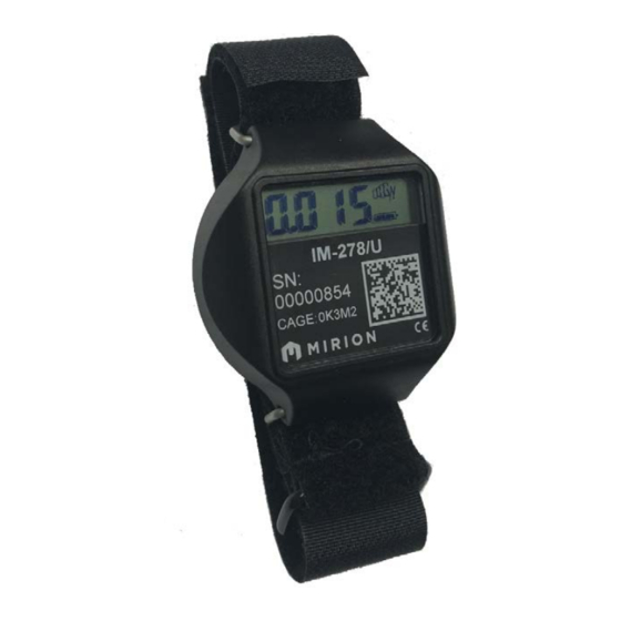
The default LCD configuration displays Total Deep Dose (sum of Gamma and Neutron) and cGy measurement units. Figure 14: MBD-2 with Active Display 4.4.4 Display Messages The MBD-2 may display messages or characters on the LCD under certain conditions of operation: Table 5: MBD-2 Display Messages Message Condition Lo.t... -
Page 17: Reading Data From The Mbd-2
Measurement data is saved in MBD-2 resident memory and the newest values over period of 15 days is maintained in the NFC chip memory. The MBD-2 is configured to perform two daily “reads”, where a dose or measurement record is saved to memory including a date and time stamp. -
Page 18: Internal Battery (Detector & Rtc) Replacement
Figure 16: MBD-2 without O-Ring and Inspection c. Install the O-Ring on the flange. Run a fingertip around the top of the O-Ring to ensure it is seated properly as shown in Figure 17, MBD-2 with Installed O-Ring below. Figure 17: MBD-2 with Installed O-Ring Internal Battery (Detector &... -
Page 19: Figure 18: Internal Battery Cover And Compartment
(i.e.; gloves, safety glasses, etc.) as applicable. e. Dispose the used batteries in accordance with site requirements. Note: the detector and real-time clock batteries shall be replaced together during scheduled maintenance. MBD-2 Operating Manual 15-00167, Rev 1... -
Page 20: C-Rings
Install the main battery in accordance with 3.2.1.1, steps f-h. C-Rings The C-Ring is 1.9mm thick stainless steel ‘C” shaped loop which is affixed to the MBD-2 by two insertion holes on opposite ends of the device case. The C-Rings are used for attaching a wrist strap or other accessory. -
Page 21: Figure 20: C-Ring Removal
Position one side of the C-Ring into the insertion hole, then the other side. e. Release the Plier tool so that the C-Ring is now secure. Swivel the C-Ring to ensure fit. Figure 21: C-Ring Replacement MBD-2 Operating Manual 15-00167, Rev 1... -
Page 22: Troubleshooting
Troubleshooting Display Messages The MBD-2 will display messages or characters on the LCD display during certain conditions. This section describes the displayed messages, their meaning and how to correct: 7.1.1 Display Messages: Problems and Resolutions Table 6: Display Message Table... -
Page 23: Parameter Error Codes: Problem And Resolution
Message: If following Error #6, indication of an intentional hard reset due to corruption of: parameter, data structure, calibration, DAC, element, BLE reset, watchdog, RTC, NFC and others, Device is resetting itself Resolution: Informational message, no action. MBD-2 Operating Manual 15-00167, Rev 1... - Page 24 Resolution: Move the device to a cooler environment and stabilize. The Hi-T message disappears. Problem: The NFC chip is not responding due to an electronics failure. NFC chip is not responding Resolution: Read-out is not possible. Remove device from service. MBD-2 Operating Manual 15-00167, Rev 1...
- Page 25 Problem: The I2C address of the NFC chip has been invalid at device start-up. The chip has not been properly initialized by the manufactured. NFC device address has been invalid Resolution: The problem is resolved by the NFC device firmware. (RESERVED) MBD-2 Operating Manual 15-00167, Rev 1...
- Page 26 Problem: The measurement result memory does not contain a valid measurement result record due to empty or corrupt flash memory Factory parameters applied Resolution: Restart device by removing and re-inserting battery. If error message repeats, remove device from service. MBD-2 Operating Manual 15-00167, Rev 1...
-
Page 27: Technical Specifications
Compliant IAW MIL-STD 810G Electrical Characteristics Main Battery (Field Replaceable): (1) Renata CR2450, 3.6 volt, lithium coin cell Autonomy: 800-1000 hours Internal (Controlled replaceable): (2) Renata CR1025 6 volt, lithium coin cell Autonomy: > 6years MBD-2 Operating Manual 15-00167, Rev 1... -
Page 28: Parts
Parts Replacement parts for the MBD-2 can be identified in Figure 22, MBD-2 Replacement Parts below Figure 22: MBD-2 Replacement Parts Item Description Part Number MBD-2 Personal Dosimeter MBD-2, complete unit only RAF 1237 058 C-Ring (2) C-Ring retainer for wrist band (each) -
Page 29: 10. Dimensional Drawing
10. Dimensional Drawing MBD-2 Operating Manual 15-00167, Rev 1...
Need help?
Do you have a question about the MBD-2 and is the answer not in the manual?
Questions and answers