Table of Contents
Advertisement
Quick Links
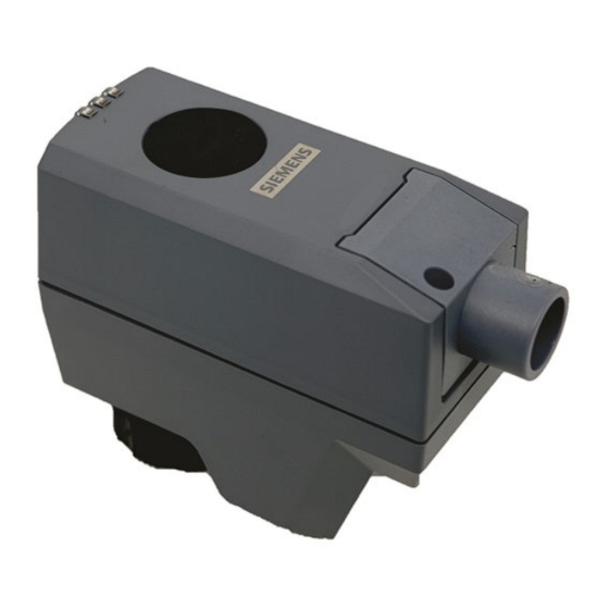
Electromotoric actuator
SSB161.05UT
A6V13359034_en--_b
2023-05-17
For pressure independent zone valves, small globe valves and 3-party valves
●
Operating voltage AC/DC 24 V, positioning signal DC 0...10 V
●
Self-calibrating to the valve stroke
●
Direct mounting with coupling nut, no tools required
●
Manually override
●
Position and actuator motion indication (LED)
●
Positioning force 200 N
●
Parallel operation of multiple actuators possible
Smart Infrastructure
Advertisement
Table of Contents

Related Manuals for Siemens SSB161.05UT


Summary of Contents for Siemens SSB161.05UT
- Page 1 Electromotoric actuator SSB161.05UT For pressure independent zone valves, small globe valves and 3-party valves ● Operating voltage AC/DC 24 V, positioning signal DC 0...10 V ● Self-calibrating to the valve stroke ● Direct mounting with coupling nut, no tools required ●...
-
Page 2: Technical Design
● Typically in chilled ceiling, VAV and fan coil unit applications ● Max.10 units of SSB161.05UT can operate in parallel, provided the controller output suffices. Technical design When the actuator is driven by DC 0…10 V positioning signal, it produces a stroke, which is transmitted to the valve stem. - Page 3 Example: Type Stock number Designation Quantity SSB161.05UT S55180-A148 Electromotoric actuator Delivery Valves and actuators must be ordered separately. For easier valve assembly, actuators ordered separately have the actuator stem fully retracted. Equipment combinations Combinable valves Type reference Valve type PN class Data sheet VVP45..
- Page 4 Environmental compatibility Environmental declarations A5W00244689A Related documents such as the environmental declarations, declarations of conformity, etc., can be downloaded from the following Internet address: www.siemens.com/bt/download Notes Engineering The actuators must be electrically connected in accordance with local regulations (see "Connection diagrams [▶...
-
Page 5: Installation
Actuator stem extends Normally open valve closes, normally closed valve opens ● Actuator stem retracts Normally open valve opens, normally closed valve closes NOTICE The actuator must be commissioned only with a correctly mounted valve in place! Siemens A6V13359034_en--_b Smart Infrastructure 2023-05-17... -
Page 6: Self-Calibration
If calibration fails, the actuator performs another calibration automatically after 10 seconds. ● After three failed calibration attempts, the actuator stem remains in the extended position and the valves are closed. The state of the LED then changes to "stays red". Siemens A6V13359034_en--_b Smart Infrastructure 2023-05-17... -
Page 7: Manual Operation
(a). Cabling operation 1. Unscrew cover screw 2. Remove cover 3. Connect or disconnect wire terminals 4. Install the cover 5. Screw in the cover screw Maintenance The actuators require no maintenance. Siemens A6V13359034_en--_b Smart Infrastructure 2023-05-17... -
Page 8: Warranty
Comply with all local and currently applicable laws and regulations. Warranty Technical data on specific applications are valid only together with Siemens products listed under "Equipment combinations". Siemens rejects any and all warranties in the event that third-party products are used. -
Page 9: Technical Data
<5 mm Mounting Connection to valve Plastic coupling nut ¾” inch Orientation 360° Standards EU conformity (CE) A5W00254962A RCM conformity A5W00254983A UKCA A5W00257055A Housing protection degree IP 54 Protection class according to EN 60730 Pollution degree Siemens A6V13359034_en--_b Smart Infrastructure 2023-05-17... -
Page 10: Fcc Regulations
1…50 ℃ -25…70 ℃ -25…70 ℃ Humidity 5…95 % r.h. <95 % r.h. 5…95 % r.h. non condensing non condensing non condensing Atmospheric Min. 700 hPa, corresponding to pressure max. 3,000 m above sea level Siemens A6V13359034_en--_b Smart Infrastructure 2023-05-17... -
Page 11: Connection Terminals
System neutral Positioning signal DC 0…10 V System potential (AC/DC 24 V) Connection diagrams N = Controller Y = Positioning signal SP, G = System potential AC 24 V SN, G0 = System neutral SN (-) Siemens A6V13359034_en--_b Smart Infrastructure 2023-05-17... -
Page 12: Revision Numbers
Dimensions 86.6 27.7 Revision numbers Type Valid from rev. no. SSB161.05UT Siemens A6V13359034_en--_b Smart Infrastructure 2023-05-17... - Page 14 Issued by © Siemens 2023 Siemens Switzerland Ltd Technical specifications and availability subject to change without notice. Smart Infrastructure Global Headquarters Theilerstrasse 1a CH-6300 Zug +41 58 724 2424 www.siemens.com/buildingtechnologies Document ID A6V13359034_en--_b Edition 2023-05-17...
Need help?
Do you have a question about the SSB161.05UT and is the answer not in the manual?
Questions and answers