Daikin FXSN71A2VEB Installation And Operation Manual
Co2 conveni-pack: indoor unit
Hide thumbs
Also See for FXSN71A2VEB:
- Installation and operation manual (24 pages) ,
- Installer and user manual (80 pages)

Related Manuals for Daikin FXSN71A2VEB


Summary of Contents for Daikin FXSN71A2VEB
- Page 1 Installation and operation manual CO₂ Conveni-Pack: indoor unit FXSN50A2VEB Installation and operation manual FXSN71A2VEB English CO₂ Conveni-Pack: indoor unit FXSN112A2VEB...
- Page 2 2P613087-1F...
-
Page 3: Table Of Contents
▪ A subset of the latest technical data is available on the regional Daikin website (publicly accessible). 13 Electrical installation ▪ The full set of latest technical data is available on the Daikin 13.1 Specifications of standard wiring components ......19 Business Portal (authentication required). -
Page 4: Specific Installer Safety Instructions
CAUTION Make sure installation, servicing, maintenance, repair and Do NOT reuse piping from previous installations. applied materials follow the instructions from Daikin and, in addition, comply with applicable legislation and are CAUTION performed by qualified persons only. In Europe and areas... -
Page 5: For The User
3 User safety instructions WARNING WARNING ▪ If the power supply has a missing or wrong N-phase, Use an all-pole disconnection type breaker with at least equipment might break down. 3 mm between the contact point gaps that provide full disconnection under overvoltage category III. -
Page 6: Instructions For Safe Operation
3 User safety instructions Instructions for safe operation the unit, and endanger the health of people who are hypersensitive to WARNING chemicals. Do NOT modify, disassemble, remove, CAUTION reinstall or repair the unit yourself as incorrect dismantling or installation NEVER expose little children, plants or may cause an electrical shock or fire. -
Page 7: About The System
4 About the system Troubleshooting (see "8 Troubleshooting" [ 4 10]) DANGER: RISK OF ELECTROCUTION WARNING To clean the air conditioner or air filter, Stop operation and shut OFF the be sure to stop operation and turn all power if anything unusual occurs power supplies OFF. -
Page 8: User Interface
5 User interface Cooling and drying Heating Indoor unit 14~24°C WB 15~27°C DB Indoor humidity ≤80% — To avoid condensation and water dripping out of the unit. If the temperature or the humidity is beyond these conditions, safety devices may be put in action and the air conditioner may not operate. -
Page 9: Special Heating Operation Modes
7 Maintenance and service 6.2.2 Special heating operation modes CAUTION After a long use, check the unit stand and fitting for Operation Description damage. If damaged, the unit may fall and result in injury. Defrost To prevent a loss of heating capacity due to frost accumulation in the outdoor unit, the system will CAUTION automatically switch to defrost operation. -
Page 10: About The Refrigerant
8 Troubleshooting In case a CO refrigerant leak is detected 2 Clean the air filter. Use a vacuum cleaner or wash with water. If the air filter is very dirty, use a soft brush and neutral ▪ the fan of the indoor unit is stopped to prevent the refrigerant from detergent. -
Page 11: Symptoms That Are Not System Malfunctions
9 Disposal Malfunction Measure Malfunction Measure The user interface displays error code A refrigerant leak may be Operation stops ▪ Check if the air filter is clogged (see filter" [ 4 9]). detected (see "7.3.1 About suddenly. "7.2.2 To clean the air A0 or U9 (or ), the fan stops and you refrigerant leak can hear a warning sound from the user... -
Page 12: For The Installer
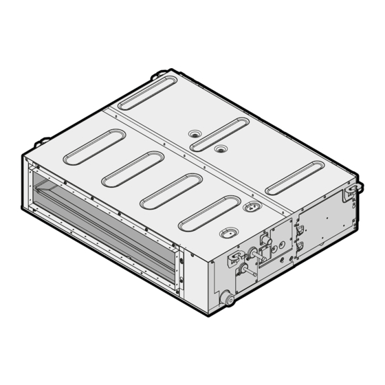
10 About the box For the installer NOTICE About the box This is a class A product. In a domestic environment this product may cause radio interference in which case the 10.1 Indoor unit user may be required to take adequate measures. ▪... -
Page 13: Additional Installation Site Requirements For Co₂ Refrigerant
11 Unit installation Installation options Appropriate measures INFORMATION Appropriate measures are field supply. Choose and install all required appropriate measures in accordance with EN 378-3:2016. ≥1100 ▪ (natural or mechanical) ventilation (mm) ▪ safety shut-off valves ▪ safety alarm, in combination with a CO refrigerant leak detector (a safety alarm alone is NOT considered an appropriate measure where occupants are restricted in their movements) -
Page 14: Mounting The Indoor Unit
11 Unit installation Example: Total refrigerant charge in the system is 45 kg and room INFORMATION volume is 300 m . 45/300=0.15, which is >QLMV (0.074) and Even if there is no refrigerating system on the lowest floor, <QLAV (0.18), therefore install at least 1 appropriate measure in the where the largest system charge (kg) in the building room. -
Page 15: Guidelines When Installing The Ducting
11 Unit installation 11.2.2 Guidelines when installing the ducting 4× CAUTION ▪ Make sure the installation of the duct does NOT exceed the setting range of the external static pressure for the unit. Refer to the technical datasheet of your model for the setting range. - Page 16 11 Unit installation ▪ Connecting the drain piping to the indoor unit To connect the drain piping to the indoor unit ▪ Checking for water leaks NOTICE General guidelines Incorrect connection of the drain hose might cause leaks, and damage the installation space and surroundings. ▪...
-
Page 17: Relocation
12 Piping installation 7 Disconnect the electrical wiring. ▪ Remove the service cover. ▪ Disconnect the power supply. ▪ Disconnect the user interface. ▪ Reattach the service cover. When installation of the system is already completed 1 Start cooling operation (see the reference guide or the service manual of the user interface). -
Page 18: Refrigerant Piping Insulation
13 Electrical installation Depending on the applicable legislation and the maximum working pressure of the unit (see "PS High" on the unit name plate), larger piping thickness might be required. 12.1.2 Refrigerant piping insulation ▪ Use polyethylene foam as insulation material: ▪... -
Page 19: Specifications Of Standard Wiring Components
13 Electrical installation 5 Power supply cable: Route the cable through the frame and WARNING connect the cable to the terminal block (L, N, earth). If the supply cord is damaged, it MUST be replaced by the manufacturer, its service agent or similarly qualified persons in order to avoid a hazard. -
Page 20: To Connect Appropriate Measures For Appliances Filled With Co₂
Daikin 1 Determine the minimum number of appropriate measures for Business Portal (authentication required). -
Page 21: To Perform A Test Run
15 Configuration To set automatic airflow adjustment The refrigerant pipes (gas and liquid) are installed correctly and thermally insulated. The automatic airflow adjustment function measures the air volume and static pressure and adjusts it towards the nominal air flow, There are NO refrigerant leaks. whatever the length of duct. -
Page 22: Technical Data
▪ A subset of the latest technical data is available on the regional Harness Daikin website (publicly accessible). H*P, LED*, V*L Pilot lamp, light emitting diode ▪ The full set of latest technical data is available on the Daikin Light emitting diode (service Business Portal (authentication required). monitor green) HIGH VOLTAGE High voltage 16.1... - Page 23 16 Technical data Symbol Meaning Insulated gate bipolar transistor (IGBT) Circuit breaker Q*DI, KLM Earth leak circuit breaker Overload protector Thermo switch Residual current device Resistor Thermistor Receiver Limit switch Float switch S*NG Refrigerant leak detector S*NPH Pressure sensor (high) S*NPL Pressure sensor (low) S*PH, HPS*...
- Page 24 4P602815-1F 2021.07 Verantwortung für Energie und Umwelt...
Need help?
Do you have a question about the FXSN71A2VEB and is the answer not in the manual?
Questions and answers