Table of Contents
Advertisement
Quick Links
Advertisement
Chapters
Table of Contents

Related Manuals for Daikin FXSQ-TAVJU Series


Summary of Contents for Daikin FXSQ-TAVJU Series
- Page 1 EDUS391777-F17 FXSQ-TAVJU MSP Concealed Ducted Unit...
-
Page 3: Table Of Contents
EDUS391777-F17 FXSQ-TAVJU MSP Concealed Ducted Unit 1. Features and Benefits ................. 2 2. Specifications ....................3 3. Dimensions ....................9 4. Piping Diagrams..................15 5. Wiring Diagrams..................16 6. Electric Characteristics................17 7. Safety Devices Setting ................18 8. Capacity Tables ..................19 8.1 Cooling Capacity at Te: 43°F (6°C) ............19 8.2 Heating Capacity .................. -
Page 4: Features And Benefits
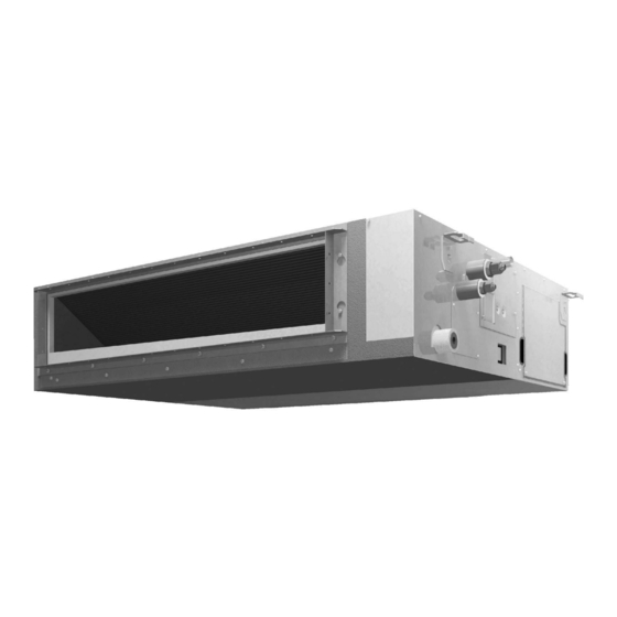
Features and Benefits EDUS391777-F17 1. Features and Benefits The FXSQ_TAVJU MSP Concealed Ducted unit gives designers a tool to approach even the most cramped air conditioning applications. Low profile chassis design measures 9-11/16" (245 mm) deep Powerful static pressure capability, with up to 0.6 in.w.g. (150 Pa) external static pressure Designed for installation flexibility, with a factory rear-return configuration and field convertible to bottom return DC fan motor with Auto* fan speed control optimizes fan energy use by intelligently controlling the fan speed in response to room temperature conditions... -
Page 5: Specifications
EDUS391777-F17 Specifications 2. Specifications MSP Concealed Ducted Unit Model FXSQ05TAVJU FXSQ07TAVJU Power supply 1 phase, 60 Hz, 208/230 V 1 phase, 60 Hz, 208/230 V Btu/h 3 Cooling capacity 5,800 (1.7) 7,500 (2.2) (kW) Btu/h 3 Heating capacity 6,500 (1.9) 8,500 (2.5) - Page 6 Specifications EDUS391777-F17 MSP Concealed Ducted Unit Model FXSQ09TAVJU FXSQ12TAVJU Power supply 1 phase, 60 Hz, 208/230 V 1 phase, 60 Hz, 208/230 V Btu/h 3 Cooling capacity 9,500 (2.8) 12,000 (3.5) (kW) Btu/h 3 Heating capacity 10,500 (3.1) 13,500 (4.0) (kW) Casing / Color Galvanized steel plate...
- Page 7 EDUS391777-F17 Specifications MSP Concealed Ducted Unit Model FXSQ15TAVJU FXSQ18TAVJU Power supply 1 phase, 60 Hz, 208/230 V 1 phase, 60 Hz, 208/230 V Btu/h 3 Cooling capacity 15,000 (4.4) 18,000 (5.3) (kW) Btu/h 3 Heating capacity 17,000 (5.0) 20,000 (5.9) (kW) Casing / Color Galvanized steel plate...
- Page 8 Specifications EDUS391777-F17 MSP Concealed Ducted Unit Model FXSQ24TAVJU FXSQ30TAVJU Power supply 1 phase, 60 Hz, 208/230 V 1 phase, 60 Hz, 208/230 V Btu/h 3 Cooling capacity 24,000 (7.0) 30,000 (8.8) (kW) Btu/h 3 Heating capacity 27,000 (7.9) 34,000 (10.0) (kW) Casing / Color Galvanized steel plate...
- Page 9 EDUS391777-F17 Specifications MSP Concealed Ducted Unit Model FXSQ36TAVJU FXSQ48TAVJU Power supply 1 phase, 60 Hz, 208/230 V 1 phase, 60 Hz, 208/230 V Btu/h 3 Cooling capacity 36,000 (10.6) 48,000 (14.1) (kW) Btu/h 3 Heating capacity 40,000 (11.7) 54,000 (15.8) (kW) Casing / Color Galvanized steel plate...
- Page 10 Specifications EDUS391777-F17 MSP Concealed Ducted Unit Model FXSQ54TAVJU Power supply 1 phase, 60 Hz, 208/230 V Btu/h 3 Cooling capacity 54,000 (15.8) (kW) Btu/h 3 Heating capacity 60,000 (17.6) (kW) Casing / Color Galvanized steel plate 9-11/16 × 61 × 31-1/2 Dimensions: (H×W×D) in.
-
Page 11: Dimensions
EDUS391777-F17 Dimensions 3. Dimensions FXSQ05TAVJU / FXSQ07TAVJU / FXSQ09TAVJU / FXSQ12TAVJU FXSQ-TAVJU... - Page 12 Dimensions EDUS391777-F17 FXSQ15TAVJU FXSQ-TAVJU...
- Page 13 EDUS391777-F17 Dimensions FXSQ18TAVJU FXSQ-TAVJU...
- Page 14 Dimensions EDUS391777-F17 FXSQ24TAVJU / FXSQ30TAVJU FXSQ-TAVJU...
- Page 15 EDUS391777-F17 Dimensions FXSQ36TAVJU / FXSQ48TAVJU FXSQ-TAVJU...
- Page 16 Dimensions EDUS391777-F17 FXSQ54TAVJU FXSQ-TAVJU...
-
Page 17: Piping Diagrams
EDUS391777-F17 Piping Diagrams 4. Piping Diagrams FXSQ05TAVJU / FXSQ07TAVJU / FXSQ09TAVJU / FXSQ12TAVJU / FXSQ15TAVJU / FXSQ18TAVJU / FXSQ24TAVJU / FXSQ30TAVJU / FXSQ36TAVJU / FXSQ48TAVJU / FXSQ54TAVJU C: 4D034245Q Unit: in. (mm) Model Liquid φ1/2 φ1/4 FXSQ05TAVJU / FXSQ07TAVJU / FXSQ09TAVJU / FXSQ12TAVJU / FXSQ15TAVJU / FXSQ18TAVJU (φ12.7) -
Page 18: Wiring Diagrams
Wiring Diagrams EDUS391777-F17 5. Wiring Diagrams FXSQ05TAVJU / FXSQ07TAVJU / FXSQ09TAVJU / FXSQ12TAVJU / FXSQ15TAVJU / FXSQ18TAVJU / FXSQ24TAVJU / FXSQ30TAVJU / FXSQ36TAVJU / FXSQ48TAVJU / FXSQ54TAVJU FXSQ-TAVJU... -
Page 19: Electric Characteristics
EDUS391777-F17 Electric Characteristics 6. Electric Characteristics FXSQ05TAVJU / FXSQ07TAVJU / FXSQ09TAVJU / FXSQ12TAVJU / FXSQ15TAVJU / FXSQ18TAVJU / FXSQ24TAVJU / FXSQ30TAVJU / FXSQ36TAVJU / FXSQ48TAVJU / FXSQ54TAVJU 4D112405 FXSQ-TAVJU... -
Page 20: Safety Devices Setting
Safety Devices Setting EDUS391777-F17 7. Safety Devices Setting Model FXSQ05TAVJU FXSQ07TAVJU FXSQ09TAVJU FXSQ12TAVJU FXSQ15TAVJU Printed circuit board fuse 250 V, 3.15 A 250 V, 3.15 A 250 V, 3.15 A 250 V, 3.15 A 250 V, 3.15 A Printed circuit board fuse 250 V, 6.3 A... -
Page 21: Capacity Tables
8. Capacity Tables Cooling Capacity at Te: 43°F (6°C) Indoor air temp. °FWB (°CWB) (Te: 43°F (6°C)) 61 (16.1) 64 (17.8) 67 (19.4) 70 (21.1) 72 (22.2) 75 (23.9) Model FXSQ05TAVJU FXSQ07TAVJU FXSQ09TAVJU 10.0 FXSQ12TAVJU 10.9 12.0 12.3 12.4 12.6 FXSQ15TAVJU 12.1... -
Page 22: Correction Factor For Cooling Capacity At Te: 48°F (9°C)
VRV Heat Pump system using a Branch Port box. Indoor air temp. °FWB (°CWB) (Te: 48°F (9°C)) Model 57 (13.9) 61 (16.1) 64 (17.8) 67 (19.4) 70 (21.1) 72 (22.2) 75 (23.9) FXSQ05TAVJU 0.66 1.14 0.69 1.18 0.73 1.14 0.80 1.07 0.83 1.06... -
Page 23: Fan Performance
EDUS391777-F17 Fan Performance 9. Fan Performance FXSQ05TAVJU / FXSQ07TAVJU FXSQ-TAVJU... - Page 24 Fan Performance EDUS391777-F17 FXSQ09TAVJU FXSQ-TAVJU...
- Page 25 EDUS391777-F17 Fan Performance FXSQ12TAVJU FXSQ-TAVJU...
- Page 26 Fan Performance EDUS391777-F17 FXSQ15TAVJU FXSQ-TAVJU...
- Page 27 EDUS391777-F17 Fan Performance FXSQ18TAVJU FXSQ-TAVJU...
- Page 28 Fan Performance EDUS391777-F17 FXSQ24TAVJU FXSQ-TAVJU...
- Page 29 EDUS391777-F17 Fan Performance FXSQ30TAVJU FXSQ-TAVJU...
- Page 30 Fan Performance EDUS391777-F17 FXSQ36TAVJU FXSQ-TAVJU...
- Page 31 EDUS391777-F17 Fan Performance FXSQ48TAVJU FXSQ-TAVJU...
- Page 32 Fan Performance EDUS391777-F17 FXSQ54TAVJU FXSQ-TAVJU...
-
Page 33: Airflow Auto Adjustment Characteristics
EDUS391777-F17 Airflow Auto Adjustment Characteristics 10. Airflow Auto Adjustment Characteristics FXSQ05TAVJU / FXSQ07TAVJU FXSQ-TAVJU... - Page 34 Airflow Auto Adjustment Characteristics EDUS391777-F17 FXSQ09TAVJU FXSQ-TAVJU...
- Page 35 EDUS391777-F17 Airflow Auto Adjustment Characteristics FXSQ12TAVJU FXSQ-TAVJU...
- Page 36 Airflow Auto Adjustment Characteristics EDUS391777-F17 FXSQ15TAVJU FXSQ-TAVJU...
- Page 37 EDUS391777-F17 Airflow Auto Adjustment Characteristics FXSQ18TAVJU FXSQ-TAVJU...
- Page 38 Airflow Auto Adjustment Characteristics EDUS391777-F17 FXSQ24TAVJU FXSQ-TAVJU...
- Page 39 EDUS391777-F17 Airflow Auto Adjustment Characteristics FXSQ30TAVJU FXSQ-TAVJU...
- Page 40 Airflow Auto Adjustment Characteristics EDUS391777-F17 FXSQ36TAVJU FXSQ-TAVJU...
- Page 41 EDUS391777-F17 Airflow Auto Adjustment Characteristics FXSQ48TAVJU FXSQ-TAVJU...
- Page 42 Airflow Auto Adjustment Characteristics EDUS391777-F17 FXSQ54TAVJU FXSQ-TAVJU...
-
Page 43: Sound Levels (Reference Data)
EDUS391777-F17 Sound Levels (Reference Data) 11. Sound Levels (Reference Data) FXSQ05TAVJU / FXSQ07TAVJU / FXSQ09TAVJU 4D110412 FXSQ-TAVJU... - Page 44 Sound Levels (Reference Data) EDUS391777-F17 FXSQ12TAVJU 4D110413 FXSQ-TAVJU...
- Page 45 EDUS391777-F17 Sound Levels (Reference Data) FXSQ15TAVJU 4D110414 FXSQ-TAVJU...
- Page 46 Sound Levels (Reference Data) EDUS391777-F17 FXSQ18TAVJU 4D110415 FXSQ-TAVJU...
- Page 47 EDUS391777-F17 Sound Levels (Reference Data) FXSQ24TAVJU 4D110416 FXSQ-TAVJU...
- Page 48 Sound Levels (Reference Data) EDUS391777-F17 FXSQ30TAVJU 4D110417 FXSQ-TAVJU...
- Page 49 EDUS391777-F17 Sound Levels (Reference Data) FXSQ36TAVJU 4D110418 FXSQ-TAVJU...
- Page 50 Sound Levels (Reference Data) EDUS391777-F17 FXSQ48TAVJU 4D110419 FXSQ-TAVJU...
- Page 51 EDUS391777-F17 Sound Levels (Reference Data) FXSQ54TAVJU 4D110420 FXSQ-TAVJU...
-
Page 52: Center Of Gravity
Center of Gravity EDUS391777-F17 12. Center of Gravity FXSQ05TAVJU / FXSQ07TAVJU / FXSQ09TAVJU / FXSQ12TAVJU / FXSQ15TAVJU / FXSQ18TAVJU / FXSQ24TAVJU / FXSQ30TAVJU / FXSQ36TAVJU / FXSQ48TAVJU / FXSQ54TAVJU 4D112399 FXSQ-TAVJU... -
Page 53: Accessories
EDUS391777-F17 Accessories 13. Accessories 13.1 Optional Accessories (for Unit) FXSQ05TAVJU FXSQ18TAVJU FXSQ07TAVJU FXSQ36TAVJU Option Note FXSQ15TAVJU FXSQ24TAVJU FXSQ54TAVJU FXSQ09TAVJU FXSQ48TAVJU FXSQ30TAVJU FXSQ12TAVJU Shield plate for side plate KDBD63A160 — C: 3D112131 13.2 Optional Accessories (for Controls) FXSQ05TAVJU FXSQ07TAVJU FXSQ09TAVJU FXSQ12TAVJU... -
Page 54: Auxiliary Heater Setting
Auxiliary Heater Setting EDUS391777-F17 14. Auxiliary Heater Setting Auxiliary Electric Heater ON/OFF Temperature Thermostat Set temperature Thermostat Toff + S (*1) Ton + S (*1) Note: *1. S value varies automatically based on the room temperature trend. : Factory setting Second Code No. -
Page 55: Appendix 1 Installation Of Fxsq-Tavju
EDUS391777-F17 Appendix 1 Appendix 1 Installation of FXSQ-TAVJU 1.Installation Manual ..................1 FXSQ-TAVJU... -
Page 56: Safety Considerations
Installation Manual EDUS391777-F17 1. Installation Manual FXSQ05TAVJU / FXSQ07TAVJU / FXSQ09TAVJU / FXSQ12TAVJU / FXSQ15TAVJU / FXSQ18TAVJU / FXSQ24TAVJU / FXSQ30TAVJU / FXSQ36TAVJU / FXSQ48TAVJU / FXSQ54TAVJU FXSQ05TAVJU FXSQ15TAVJU FXSQ36TAVJU VRV SYSTEM FXSQ07TAVJU FXSQ18TAVJU FXSQ48TAVJU Inverter Installation manual FXSQ09TAVJU FXSQ24TAVJU... - Page 57 EDUS391777-F17 Installation Manual Make sure that all wiring is secured, that specified wires Since R410A is a blend, the required additional refrigerant must be charged in its liquid state. If the refrigerant is connections or wires. Improper connections or installation charged in a state of gas, its composition can change and may result in fire.
-
Page 58: Before Installation
Installation Manual EDUS391777-F17 2. BEFORE INSTALLATION (10) Wire sealing (11) Washer for Name (9) Washer clamp material hanger When unpacking the indoor unit or moving the unit after unpacked, hold the hangers (4 places) and do not apply Quantity 4 pcs. 2 sheets 8 pcs. -
Page 59: Selection Of Installation Location
EDUS391777-F17 Installation Manual Points of the operation explanation Check Items to be checked In case of defective column In addition to the general usage, since the items in the Are the sizes of electric operation manual with the WARNING and Does not operate ·... -
Page 60: Preparation Before Installation
Installation Manual EDUS391777-F17 [ Required installation space [in. (mm)] ] 4. PREPARATION BEFORE INSTALLATION Figures indicate the minimum required installation space. (1) Check the relation of location between the ceiling opening and the indoor unit hanging bolts. (unit [in. (mm)]) Provide one of the following service spaces for the drain pump or for other services. - Page 61 EDUS391777-F17 Installation Manual Ceiling framework reinforcement may be required in Control box order to keep the ceiling horizontal and prevent ceiling vibration after opening the ceiling holes. For details, consult your building and upholstery work contractors. Ceiling (5) Install the hanging bolts. Use either a M8-M10 size bolt or equivalent.
-
Page 62: Installation Of Indoor Unit
Installation Manual EDUS391777-F17 Washer clamp (9) (accessory) Washer for (accessory) Fig. 7 Keep the air outlet covered with a protective sheet to pre- vent weld spatter and other foreign materials from entering the indoor unit and damaging the resin drain pan. (If holes or cracks are generated in the resin drain pan, water can leak.) (2) Adjust so that the unit is properly positioned. -
Page 63: Refrigerant Piping Work
EDUS391777-F17 Installation Manual 6. REFRIGERANT PIPING WORK Table 2 Piping Tightening Dimension for For the outdoor unit refrigerant piping, refer to the installa- Flare shape size torque [in. (mm)] tion manual attached to the outdoor unit. [in. (mm)] [lbf·ft. (N·m)] A [in. - Page 64 Installation Manual EDUS391777-F17 After leak test, referring to Fig. 11, insulate both the gas and liquid piping connection with the attached joint through the refrigerant piping and substitute air with insulating material (4) and (5) to prevent the pipings from nitrogen (NOTE 1) (Refer to Fig.
-
Page 65: Drain Piping Work
EDUS391777-F17 Installation Manual 7. DRAIN PIPING WORK Wrap the vinyl tape around the end of the metal clamp (1) so that the sealing material (Large) (6) to be used at (1) Carry out drain piping. Carry out drain piping so that drainage is ensured. end or bend the tip of the metal clamp (1) inward as Select the piping diameter equal to or larger than shown. - Page 66 Installation Manual EDUS391777-F17 < Caution to be taken when carrying out upward CAUTION drain piping (Refer to Fig. 16) > force, do not bend nor twist it. (675 mm). Since the drain pump mounted on this It may cause water leakage. indoor unit is a high head type, from the characteristic As for drain piping connection, do not connect the drain point of view, the higher the drain riser the lower the...
- Page 67 EDUS391777-F17 Installation Manual smoothly. may result in malfunction) Do not touch the drain pump. Touching the drain pump may cause electric Gradually pour 1/4 gal. (1 ) of water from the inspec- shocks. tion hatch at the bottom of the drain socket on the left side of the drain socket into the drain pan giving 5.
-
Page 68: Duct Work
Installation Manual EDUS391777-F17 8. DUCT WORK 9. ELECTRIC WIRING WORK Pay the utmost attention to the following items and con- 9-1 GENERAL INSTRUCTIONS duct the ductwork. Make certain that all electric wiring work is carried out by and this installation manual, using a separate dedicated datasheet for the setting range.) circuit. - Page 69 9-4 WIRING CONNECTION METHOD Voltage CAUTION FOR WIRING Model Hz Volts MCA MOP range For connection to the terminal block, use ring type crimp style terminals with insulation sleeve or insulate the wirings FXSQ05TAVJU 0.078 properly. FXSQ07TAVJU 0.078 Wiring Insulation sleeve FXSQ09TAVJU 0.078 FXSQ12TAVJU 0.078...
- Page 70 Installation Manual EDUS391777-F17 Hook WARNING Conduit mounting When wiring, form the wirings orderly so that the control plate (12) Screws in place, the wirings may come out or be sandwiched by the (2 points) (1) Remove the control box lid. Fig.
- Page 71 EDUS391777-F17 Installation Manual (5) Mount the control box lid and wrap the wire sealing < No. 2 system: When carrying out group control or 2 material (small) (10) so that the wiring through hole remote controller control. > will be covered by the sealing material. Power supply Power supply Power supply...
-
Page 72: Field Setting
Installation Manual EDUS391777-F17 9-6 FOR CONTROL WITH 2 REMOTE CONTROL- 9-8 FOR REMOTE CONTROL (FORCE OFF OR ON / LERS (TO CONTROL 1 INDOOR UNIT WITH 2 OFF OPERATION) REMOTE CONTROLLERS) For control with 2 remote controllers, set one remote con- input to the terminal T1 and T2 on the terminal block for troller as Main and the other remote controller as Sub. - Page 73 EDUS391777-F17 Installation Manual 10-1 Settings for external static pressure CAUTION Make settings in either method (a) or method (b). (a) Make settings with Air volume automatic adjust- changes, are made after air volume adjustments, be sure to ment function. make “Air volume automatic adjustment” again. “Air volume automatic adjustment”...
-
Page 74: Test Operation
Installation Manual EDUS391777-F17 Table 9 11. TEST OPERATION Mode FIRST SECOND After cleaning the indoor unit inside, carry out test operation Setting CODE No. CODE No. according to installation manual attached to the outdoor Fan speed during unit. cooling 12 (22) thermostat OFF Setting shows that something is abnormal. - Page 76 Improper installation can result in water or refrigerant leakage, electrical shock, fire or explosion. Use only those parts and accessories supplied or specified by Daikin. Ask a qualified installer or contractor to install those parts and accessories. Use of unauthorised parts and accessories or improper installation of parts and accessories can result in water or refrigerant leakage, electrical shock, fire or explosion.
Need help?
Do you have a question about the FXSQ-TAVJU Series and is the answer not in the manual?
Questions and answers