Daikin FXSN50A2VEB Installation And Operation Manual
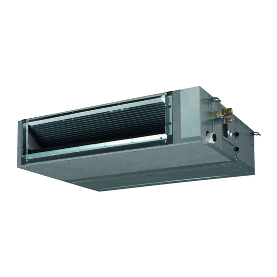
Co2 conveni-pack: indoor unit
Hide thumbs
Also See for FXSN50A2VEB:
- Installation and operation manual (24 pages) ,
- Installer and user manual (80 pages)

Related Manuals for Daikin FXSN50A2VEB


Summary of Contents for Daikin FXSN50A2VEB
- Page 1 Installation and operation manual CO₂ Conveni-Pack: indoor unit FXSN50A2VEB Installation and operation manual FXSN71A2VEB English CO₂ Conveni-Pack: indoor unit FXSN112A2VEB...
- Page 2 2P613087-1...
-
Page 3: Table Of Contents
Daikin website (publicly accessible). 13.1 Specifications of standard wiring components ......19 ▪ The full set of latest technical data is available on the Daikin 13.2 To connect the electrical wiring to the indoor unit ..... 19 Business Portal (authentication required). -
Page 4: Specific Installer Safety Instructions
CAUTION Make sure installation, servicing, maintenance, repair and Do NOT reuse piping from previous installations. applied materials follow the instructions from Daikin and, in addition, comply with applicable legislation and are CAUTION performed by qualified persons only. In Europe and areas... -
Page 5: For The User
3 User safety instructions WARNING WARNING ▪ All wiring MUST be performed by an authorised Use an all-pole disconnection type breaker with at least electrician and MUST comply with the applicable 3 mm between the contact point gaps that provide full legislation. - Page 6 3 User safety instructions (field supply), in order to be effective, CAUTION the unit must be electrically powered at NEVER expose little children, plants or all times after installation, except for animals directly to the airflow. short service periods. WARNING CAUTION Do NOT place objects below the indoor Do NOT insert fingers, rods or other...
-
Page 7: About The System
4 About the system Troubleshooting (see "8 Troubleshooting" [ 4 10]) DANGER: RISK OF ELECTROCUTION WARNING To clean the air conditioner or air filter, Stop operation and shut off the be sure to stop operation and turn all power if anything unusual occurs power supplies off. -
Page 8: User Interface
5 User interface ▪ The air flow rate may adjust itself depending on the room temperature or the fan may stop immediately. This is not a malfunction. ▪ If the main power supply is turned off during operation, operation will restart automatically after the power turns back on again. ▪... -
Page 9: Maintenance And Service
7 Maintenance and service Clean with a soft cloth. If it is difficult to remove stains, use water or Maintenance and service a neutral detergent. 7.2.2 To clean the air filter Precautions for maintenance and service When to clean the air filter: ▪... -
Page 10: About Refrigerant Leak Detection
8 Troubleshooting WARNING Troubleshooting ▪ Do NOT pierce or burn refrigerant cycle parts. If one of the following malfunctions occur, take the measures shown ▪ Do NOT use cleaning materials other than those below and contact your dealer. recommended by the manufacturer. WARNING ▪... -
Page 11: Symptoms That Are Not System Malfunctions
9 Disposal 8.1.1 Symptom: The system does not operate Malfunction Measure The system operates ▪ Check if air inlet or outlet of outdoor or ▪ The air conditioner does not start immediately after the ON/OFF but cooling or heating indoor unit is not blocked by obstacles. button on the user interface is pressed. -
Page 12: For The Installer
10 About the box For the installer About the box 10.1 Indoor unit ≥500 10.1.1 To remove the accessories from the indoor unit 1× 1× 8× 40× 1× 3× 1× (mm) Minimum distance to the floor 2.7 m to avoid accidental touching 2.5 m in case the fan is covered (e.g. -
Page 13: Additional Installation Site Requirements For Co₂ Refrigerant
11 Unit installation WARNING When using safety shut-off valves, make sure to install measures such as a bypassing piping with a pressure relief valve (from liquid pipe to gas pipe). When the safety shut- off valves close and no measures are installed, increased ≥1100 pressure may damage the liquid piping. -
Page 14: Mounting The Indoor Unit
11 Unit installation QLAV QLMV INFORMATION Even if there is no refrigerating system on the lowest floor, where the largest system charge (kg) in the building divided by total volume of the lowest floor (m ) exceed the value for QLMV, provide a mechanical ventilation in accordance with EN 378-3:2016. -
Page 15: Guidelines When Installing The Ducting
11 Unit installation 11.2.2 Guidelines when installing the ducting 4× CAUTION ▪ Make sure the installation of the duct does NOT exceed the setting range of the external static pressure for the unit. Refer to the technical datasheet of your model for the setting range. - Page 16 11 Unit installation ▪ General guidelines To connect the drain piping to the indoor unit ▪ Connecting the drain piping to the indoor unit NOTICE ▪ Checking for water leaks Incorrect connection of the drain hose might cause leaks, and damage the installation space and surroundings. General guidelines ▪...
-
Page 17: Relocation
12 Piping installation 7 Disconnect the electrical wiring. ▪ Remove the service cover. ▪ Disconnect the power supply and user interface. ▪ Reattach the service cover. When installation of the system is already completed 1 Start cooling operation (see the reference guide or the service manual of the user interface). -
Page 18: Connecting The Refrigerant Piping
13 Electrical installation Pipe outer diameter Insulation inner Insulation thickness (Ø diameter (Ø 9.5 mm (3/8") 10~14 mm ≥10 mm 12.7 mm (1/2") 14~16 mm ≥10 mm Ø Ø Ø Ø If the temperature is higher than 30°C and the humidity is higher than RH 80%, the thickness of the insulation materials should be at least 20 ... -
Page 19: Specifications Of Standard Wiring Components
13 Electrical installation 5 Power supply cable: Route the cable through the frame and WARNING connect the cable to the terminal block (L, N, earth). If the supply cord is damaged, it MUST be replaced by the manufacturer, its service agent or similarly qualified persons in order to avoid a hazard. -
Page 20: To Connect Appropriate Measures For Appliances Filled With Co₂
14 Commissioning Control box IN/D OUT/D P1 P2 F1 F2 T1 T2 P1 P2 P1 P2 F1 F2 T1 T2 P1 P2 Outdoor unit Indoor unit User interface (controls 3 indoor units) Most downstream indoor unit For use with 2 user interfaces P1 P2 F1 F2 T1 T2 ▪... -
Page 21: To Perform A Test Run
15 Configuration ▪ External static pressure setting using: The power supply voltage matches the voltage on the identification label of the unit. ▪ Automatic airflow adjustment setting There are NO loose connections or damaged electrical ▪ User interface components in the switch box. ▪... -
Page 22: Technical Data
▪ A subset of the latest technical data is available on the regional refer to PCB inside your unit) Daikin website (publicly accessible). Connector (frame ground) ▪ The full set of latest technical data is available on the Daikin Harness Business Portal (authentication required). H*P, LED*, V*L... - Page 23 16 Technical data Symbol Meaning Symbol Meaning Intelligent eye sensor Ferrite core IPM* Intelligent power module ZF, Z*F Noise filter K*R, KCR, KFR, KHuR, K*M Magnetic relay Live Coil Reactor Stepper motor Compressor motor Fan motor Drain pump motor Swing motor MR*, MRCW*, MRM*, MRN* Magnetic relay Neutral...
- Page 24 4P602815-1C 2020.05 Verantwortung für Energie und Umwelt...
Need help?
Do you have a question about the FXSN50A2VEB and is the answer not in the manual?
Questions and answers