Table of Contents
Advertisement
Quick Links
A l l t e s t I n s t r u me n t s , I n c .
5 0 0 C e n t r a l A v e .
F a r mi n g d a l e , N J 0 7 7 2 7
P : ( 7 3 2 ) 9 1 9 - 3 3 3 9
F : ( 7 3 2 ) 9 1 9 - 3 3 3 2
a l l t e s t . n e t
s s a l e s @ a l l t e s t . n e t
T h e t e s t & me a s u r e me n t
e q u i p me n t y o u n e e d a t
t h e p r i c e y o u w a n t .
A l l t e s t c a r r i e s t h e w o r l d ' s l a r g e s t s e l e c t i o n o f
u s e d / r e f u r b i s h e d b e n c h t o p t e s t & me a s u r e me n t
e q u i p me n t a t 5 0 % t h e p r i c e o f n e w .
O O u r e q u i p me n t i s g u a r a n t e e d w o r k i n g , w a r r a n t i e d , a n d
a v a i l a b l e w i t h c e r t i f i e d c a l i b r a t i o n f r o m o u r i n - h o u s e s t a f f
o f t e c h n i c i a n s a n d e n g i n e e r s .
• 1 0 + f u l l t i me t e c h n i c i a n s w i t h o v e r 1 5 0 y e a r s o f
s p e c i a l i z a t i o n
• 9 0 d a y w a r r a n t y & 5 d a y r i g h t o f r e t u r n o n a l l
e q u i p me n t
• • 1 - 3 y e a r w a r r a n t i e s f o r n e w a n d
p r e mi u m- r e f u r b i s h e d e q u i p me n t
• E v e r y u n i t t e s t e d t o O E M s p e c i f i c a t i o n s
• S a t i s f a c t i o n g u a r a n t e e d
Y o u h a v e p l a n s , w e w i l l h e l p y o u a c h i e v e t h e m.
A n y p r o j e c t . A n y b u d g e t .
t
G e t a q u o t e t o d a y !
C C a l l ( 7 3 2 ) 9 1 9 - 3 3 3 9 o r e ma i l s a l e s @a l l t e s t . n e t .
Advertisement
Table of Contents

Related Manuals for Tektronix TG 2000


Summary of Contents for Tektronix TG 2000
- Page 1 T h e t e s t & me a s u r e me n t e q u i p me n t y o u n e e d a t t h e p r i c e y o u w a n t . A l l t e s t I n s t r u me n t s , I n c .
- Page 2 User Manual TG 2000 Signal Generation Platform 070-9108-01 This document supports software version 2.0 and above.
- Page 3 Copyright Tektronix, Inc. All rights reserved. Tektronix products are covered by U.S. and foreign patents, issued and pending. Information in this publication supercedes that in all previously published material. Specifications and price change privileges reserved. Printed in the U.S.A. Tektronix, Inc., P.O. Box 1000, Wilsonville, OR 97070–1000...
- Page 4 Tektronix, with shipping charges prepaid. Tektronix shall pay for the return of the product to Customer if the shipment is to a location within the country in which the Tektronix service center is located.
- Page 5 Eliminates unexpected service expenses For Information and Ordering For more information or to order Service Assurance, contact your Tektronix representative and provide the information below. Service Assurance may not be available in locations outside the United States of America. Name...
-
Page 6: Table Of Contents
Touch Screen and Front-Panel Controls ....... 2–10 TG 2000 Signal Generation Platform User Manual... - Page 7 ..........3–10 TG 2000 Signal Generation Platform User Manual...
- Page 8 ........3–57 TG 2000 Signal Generation Platform User Manual...
- Page 9 3–103 :SENSe:ROSCillator:FRAMe2:CATalog? ......3–104 TG 2000 Signal Generation Platform User Manual...
- Page 10 ........C–1 TG 2000 Signal Generation Platform User Manual...
- Page 11 ..........E–9 Glossary and Index TG 2000 Signal Generation Platform User Manual...
- Page 12 ....1–7 Figure 1–4: Placing the TG 2000 Signal Generation Platform in the rack ..........
- Page 13 ........E–6 viii TG 2000 Signal Generation Platform User Manual...
- Page 14 Table E–1: Module slot assignments ......E–2 TG 2000 Signal Generation Platform User Manual...
- Page 15 Table of Contents TG 2000 Signal Generation Platform User Manual...
-
Page 16: General Safety Summary
Provide Proper Ventilation. To prevent product overheating, provide proper ventilation. Do Not Operate With Suspected Failures. If you suspect there is damage to this product, have it inspected by qualified service personnel. TG 2000 Television Generation Platform User Manual... - Page 17 DANGER Protective Ground ATTENTION Double High Voltage (Earth) Terminal Refer to Manual Insulated Certifications and Refer to the specifications section for a listing of certifications and compliances Compliances that apply to this product. TG 2000 Television Generation Platform User Manual...
-
Page 18: Service Safety Summary
Use Care When Servicing With Power On. Dangerous voltages or currents may exist in this product. Disconnect power and disconnect test leads before removing protective panels, soldering, or replacing components. To avoid electric shock, do not touch exposed connections. xiii TG 2000 Television Generation Platform User Manual... - Page 19 Service Safety Summary TG 2000 Television Generation Platform User Manual...
-
Page 20: Preface
Related Manuals The following documents are also available for the platform: The TG 2000 Signal Generation Platform User Manual describes how to use the TG 2000 Platform. It also contains information about SCPI commands, programming structure, and status and events for the platform. Some of this information applies to all generator modules, including the DVG1 Generator module. - Page 21 Preface The TG 2000 Signal Generation Platform Service Manual describes how to service the mainframe to the module level and provides general information about servicing generator modules. This optional manual must be ordered separately. A module user manual is included with each optional module. Contact your Tektronix representative for a list of generator and special function modules.
-
Page 23: Getting Started
The TG 2000 Signal Generation Platform addresses the needs of research and development, engineering, manufacturing test, and most operational environ- ments. -
Page 24: Accessories
Flash EPROM allows easy upgrades to system software Accessories This section describes the key accessories for the TG 2000 Signal Generation Platform. For a complete list of accessories and their Tektronix part numbers, refer to the Replaceable Mechanical Parts list at the back of this manual. -
Page 25: Gpib Card For Sdp2000 Communications
Configuration The TG 2000 Signal Generation Platform mainframe requires configuration for the installation of new modules and for the AC line voltage. The TG 2000 Signal Generation Platform mainframe is configured at the factory to support the optional module generators that you order. Modules ordered separately should be installed by a qualified service technician. -
Page 26: Figure 1-1: Location Of Power Connections And Configuration
Line Voltage Setting Fuse Rating 115 V Slow blow, 6 AT 230 V Slow blow, 3 AT Line selector Fuse Power switch AC Line connecter Figure 1–1: Location of power connections and configuration 1–4 TG 2000 Signal Generation Platform User Manual... -
Page 27: Cpu Configuration Switch
The rotary switch shown in Figure 1–2 is for use by service technicians only. The switch must be in position “0” for normal operation. Figure 1–2: Location of the service diagnostics switch 1–5 TG 2000 Signal Generation Platform User Manual... -
Page 28: Installation
Hardware Installation The TG 2000 Signal Generation Platform is shipped with the optional generator modules that you ordered configured and installed. Only qualified service technicians should install modules in the TG 2000 Signal Generation Platform mainframe. -
Page 29: Figure 1-3: Installing The Rackmount Hardware
Stop latch hole Rear rack 10–32 Phs screws Flat bar nut Front rack Flat bar nut (Use if front rail is not tapped) 10–32 Phs screws Figure 1–3: Installing the rackmount hardware 1–7 TG 2000 Signal Generation Platform User Manual... -
Page 30: Software Installation
1. Slide the mainframe out until it stops at the catches. 2. Support the mainframe while you press in on the stop latch buttons on each side. This action will free the TG 2000 Signal Generation Platform to slide completely out of the rack. -
Page 31: Power-On Procedure
The platform recalls the settings that were active when powered off. Power-on settings are stored in nonvolatile memory. NOTE. If your TG 2000 Signal Generation Platform powers on, but a module fails to appear in the Modules window, the module may require service. Refer to the appropriate service manual for assistance (service manuals for the main- frame and modules are optional accessories). -
Page 32: Incoming Inspection
Status key and check that no module has a “Failed power up” status. Refer to the module User manual for further checks on each module. 4. Wait 20 minutes for the TG 2000 Signal Generation Platform and its generator modules to warm up. - Page 33 Getting Started Self cal takes 2 to 5 minutes depending on the module. An error message indicates a failed calibration. If the self cal fails, contact your Tektronix Representative. 6. Check the LCD display as follows: a. Push the Screen Contrast button on the right side of the front panel.
- Page 34 A continued failure may indicate a defective disk drive. 8. Connect the Clock output from the BG1 Generator module to the frequency counter as shown in Figure 1–5. 1–12 TG 2000 Signal Generation Platform User Manual...
-
Page 35: Figure 1-5: Hooking Up The Clock Output To The Frequency Counter
Tektronix Representative. 12. Restore the clock frequency noted in step 10f. You have completed the incoming inspection procedure for the mainframe. Proceed to the Incoming Inspection procedures in your module user manuals. 1–13 TG 2000 Signal Generation Platform User Manual... - Page 36 Getting Started 1–14 TG 2000 Signal Generation Platform User Manual...
-
Page 38: Functional Overview
Front Panel Overview Touch Screen and Front-Panel Controls Rear Panel Connectors and Controls Figure 2–1 shows a simplified block diagram of the TG 2000 Signal Generation Platform. System Control As shown in Figure 2–1, the mainframe CPU coordinates front panel and remote interface commands and uses that input to set up the modules, the clock, and the optional AGL1 Genlock module. -
Page 39: Generator Modules
Figure 2–1: TG 2000 Signal Generation Platform simplified block diagram Generator Modules There are eleven module slots in the TG 2000 Signal Generation Platform. The Clock and CPU modules are required for system operation and permanently occupy two special slots (they must be installed in these slots). The black burst... -
Page 40: Black Burst Module
The TG 2000 Signal Generation Platform can supply different standard formats (such as PAL and NTSC) at the same time, using the 27 MHz clock or the two adjustable clocks and the two frame reset pulses. -
Page 41: External Reference Genlock
AGL1 Analog Genlock Module User Manual for a list of the supported formats. Timing References The TG 2000 Signal Generation Platform supports internal or external refer- ences and signal delay relative to this reference. Video reference signals synchronize the start of test signals of the same type, such as NTSC or PAL. For using external references, the AGL1 module is required. -
Page 42: Module Timing Delay
The delay is by a number of vertical lines plus a horizontal delay up to the duration of one scan line. The delay is set in the Module Timing window. Note that the variable system clocks also support module delay. 2–5 TG 2000 Signal Generation Platform User Manual... -
Page 43: System Reference Delay With The Agl1 Module
Figure 2–5 shows how the AGL1 Genlock module can delay its lock signal to with the AGL1 Module effectively delay the TG 2000 Signal Generation Platform clock and frame pulses to all modules. Delaying the clock and frame pulses results in a corre- sponding delay in the module output. -
Page 44: Test Signals
Active Signal Parameters window Selections depend on which module is Selections depend on which module is selected. Refer to module user manuals. selected. Refer to module user manuals. Figure 2–6: Module and test signal hierarchy 2–7 TG 2000 Signal Generation Platform User Manual... -
Page 45: Shared Module Memory
(refer to Save Signals to Disk on page C–2). After removing the module, you can load the desired signals from the disk into the remaining modules, as space permits. 2–8 TG 2000 Signal Generation Platform User Manual... -
Page 46: Front Panel Overview
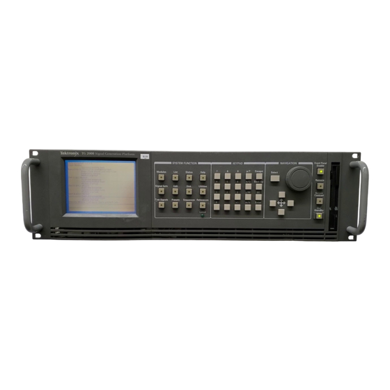
Functional Overview Front Panel Overview Figure 2–7 shows the major features of the TG 2000 Signal Generation Platform front panel. Control is through the touch-screen display, the System Function buttons, and the Navigation controls. In most cases, function buttons display a window of selections related to the button name. -
Page 47: Touch Screen And Front-Panel Controls
Location of the selected Status bar Window title module within the mainframe Signal set and name of active signal Selected item Icons for selectable modules List box Figure 2–8: Main display features 2–10 TG 2000 Signal Generation Platform User Manual... - Page 48 Figure 2–8. Window title shows the window name which indicates the selected function. NOTE. Several icons appear in more than one location. For your convenience, these icons appear in windows where appropriate. 2–11 TG 2000 Signal Generation Platform User Manual...
-
Page 49: System Function Windows
Status button and check for an error message associated with the module. Signal Sets Window. The Signal Sets window displays all of the signal sets available for the selected module. The following example is a signal set window 2–12 TG 2000 Signal Generation Platform User Manual... - Page 50 Module Parameters and Active Signal Parameters windows which are accessed through the Test Signals window. For information on these module-specific capabilities, refer to the module user manuals. 2–13 TG 2000 Signal Generation Platform User Manual...
- Page 51 AUTOSTRT. You can load the start-up sequence into memory or leave a disk in the disk drive at power on. Refer to Sequence Programming on page 3–13 for information on creating sequence files. 2–14 TG 2000 Signal Generation Platform User Manual...
- Page 52 Utilities Window. The Utilities window provides access to housekeeping functions, such as setting the date, setting the display timeout, and running self calibration. The Diagnostic selection is for use by Tektronix only. A switch, shown in Figure 1–2, is designed for use with the diagnostics. This switch should be left in position 0 for normal operation References Window.
-
Page 53: Cursor Buttons And Knob
You can browse test signals for a module, but the output does not change until you push the Select button or the signal icon. Figure 2–10 shows how to access a test signal list by selecting the test signal icon and turning the knob. 2–16 TG 2000 Signal Generation Platform User Manual... -
Page 54: Figure 2-10: Using The Knob To Open A List Of Signals
When you find a test signal using the browse mode, push the Select button to output the signal. You can use the Select button to sequence through items within an icon when it contains several selections. 2–17 TG 2000 Signal Generation Platform User Manual... -
Page 55: Keypad
4.2 EE 6 enters the value 4.2x10 Enter Changes the parameter value to the new value The TG 2000 Signal Generation Platform determines which of the two units is appropriate based on the parameter being set. 2–18 TG 2000 Signal Generation Platform User Manual... - Page 56 On/Standby Switch. Pressing the On/Standby switch turns the instrument off after all critical processes have been completed, leaving the TG 2000 Signal Generation Platform in a known state. This switch is different from the rear-pan- el on/off switch, which immediately shuts off power to the instrument regardless of any functions in process.
- Page 57 Functional Overview 2–20 TG 2000 Signal Generation Platform User Manual...
-
Page 58: Operating Procedures
Operating Procedures This section provides instructions for using the TG 2000 Signal Generation Platform menus. The topics are in alphabetical order. For module-specific functions, refer to the appropriate module user manual. Allocating System Resources You can disable clock clients and frame reset clients to free up system resources. -
Page 59: Frame Reset Allocation
SECAM, the Frame Reset Allocation window opens. In this window, you can either disable one of the clients of a frame reset to free it for use by the new format, or touch Cancel to stop loading the new format. 2–22 TG 2000 Signal Generation Platform User Manual... -
Page 60: Calibration
Calibration Refer to Self Calibration on page 2–35. Date/Time Set Use this window to set the date and time of the TG 2000 Signal Generation Platform. 1. Push the Utilities button. 2. Touch Set Date/Time to open the following window. -
Page 61: Front Panel Enable And Timeout
Navigation control, to display the Screen Timeout settings. 4. Use the Navigation arrows to browse through the list of timeout settings. 5. Push the Select button to select a new timeout value or OFF. 6. Touch Quit to exit. 2–24 TG 2000 Signal Generation Platform User Manual... -
Page 62: Help
Use the Navigation arrows to scroll up or down in the Help window. Touch Quit to leave the current Help window and return to the previous window. Push the Help button twice for general help information. 2–25 TG 2000 Signal Generation Platform User Manual... -
Page 63: Locked Led
Illuminated: the TG 2000 Signal Generation Platform is locked to the external reference. Blinking: the TG 2000 Signal Generation Platform is attempting to lock or unable to lock to the external reference. Check that the incoming signal matches the type chosen in the Reference Select window. Also, ensure that the signal line is properly terminated at the AGL1 loop through connector or at distant equipment connection. -
Page 64: Module Status
The Status window also lists configuration information for an installed AGL1 module. AGL1 information appears at the bottom of the display. The following example shows a Status window with AGL1 module information. 2–27 TG 2000 Signal Generation Platform User Manual... -
Page 65: Presets
2. Touch Presets on the display. 3. Touch Create at bottom of the display. 4. In the text entry window, enter the name for your new preset. The name is limited to eight characters. 2–28 TG 2000 Signal Generation Platform User Manual... -
Page 66: Save Current Settings To An Existing Preset
Recall restores the instrument settings stored in the selected preset. Current settings are not saved. Recalling the Factory preset restores the TG 2000 Signal Generation Platform and all installed modules to factory default settings. Rename lets you give an existing preset a new name. In the text entry window, enter the new name for your preset. -
Page 67: References
Module Timing Use the Module Timing window to advance or delay the outputs for capable modules relative to a TG 2000 Signal Generation Platform frame reset signal or to an external video reference (when using the AGL1 Genlock module). Module timing is specified only between modules using the same basic format, such as NTSC or PAL. - Page 68 To add a delay of one or more vertical lines, touch Vertical. Enter a value up to the number of lines in all fields in the frame. The delay limit is plus or minus half a frame. 2–31 TG 2000 Signal Generation Platform User Manual...
-
Page 69: Select Reference
References window. Only modules using compatible formats are affected. To set up a TG 2000 Signal Generation Platform to lock on or synchronize to an external reference, follow these steps: 1. Ensure that an AGL1 Generator module is installed in the platform. -
Page 70: Reference Timing
Provides control of the timing offset relative to the Ref ports of the AGL1 module. To set an advance or delay of the TG 2000 Signal Generation Platform relative to an external reference, follow these steps: 1. Push the References button. -
Page 71: Renaming A Module
Default. (If you have already saved a new name and exited the window, push Modules and then push Edit to get back to the Rename Module window. Then touch Rename Module and Reset to Default.) 2–34 TG 2000 Signal Generation Platform User Manual... -
Page 72: Self Calibration
6. Touch Start Cal to begin calibration of the selected modules. The number of modules selected determines the time required for calibration. 7. Check that no errors are displayed during calibration. 2–35 TG 2000 Signal Generation Platform User Manual... -
Page 73: Sequences
4. Select the sequence file you wish to load. In the following figure, SEQ1 is selected to load. 5. Touch Start Load to load the sequence into the TG 2000 Signal Generation Platform. 6. Choose another sequence to load or touch Quit. -
Page 74: Run A Sequence
2. A dialog box appears. Choose one of the options; Yes, Yes to All, no or cancel. 3. If you don’t want to stop the sequence, touch No or Cancel. 4. To exit the Sequences window, touch Quit. 2–37 TG 2000 Signal Generation Platform User Manual... -
Page 75: Screen Contrast
You can also touch the list box area at the top of the screen or turn the knob to display the list of available signals within the selected group of test signals. Move the browse ring to the desired signal and then push the Select button. 2–38 TG 2000 Signal Generation Platform User Manual... -
Page 76: Versions
5. To exit this window, push another System Function button. Versions The Versions window displays software and hardware versions of the TG 2000 Signal Generation Platform and all installed modules. Be sure to include this information when reporting any problems with your TG 2000 Signal Generation Platform or an installed module. - Page 77 Operating Procedures 2–40 TG 2000 Signal Generation Platform User Manual...
-
Page 79: Syntax
1. Select the module to be addressed before executing any commands. Many of the commands used by the TG 2000 Signal Generation Platform are shared by several modules and will be accepted without a reported error. -
Page 80: Argument Example
DOWN. Use this argument to decrease the parameter value one increment as defined by the :STEP value. NOTE. If the TG 2000 Signal Generation Platform does not return a value in response to a MIN or MAX query, then the values are undefined and an error message is generated. - Page 81 Syntax changes the amplitude to 127 percent. changes the amplitude to 0 percent. changes the circle diameter to 2 percent. disables the module and removes the displayed test signal. 3–3 TG 2000 Signal Generation Platform User Manual...
-
Page 82: Scpi Commands And Queries
This environment uses defined programming messages, instrument responses, and data format across all SCPI instruments, regardless of manufacturer. The TG 2000 Signal Generation Platform uses a command language based on the SCPI standard. -
Page 83: Parameter Types
The parameters are enclosed in brackets, such as <pattern>. The parameter type is listed after the parameter and is enclosed in parentheses, for example, (discrete). Some parameter types are defined specifically for the TG 2000 Signal Generation Platform command set and some are defined by ANSI/IEEE 488.2-1987 (see Table 3–1). -
Page 84: Abbreviating Commands, Queries, And Parameters
NOTE. The numeric suffix of a command or query may be included in either the long form or short form; the TG 2000 Signal Generation Platform will default to “1” if no suffix is used. In Figure 3–2, the “3” of “VID3” indicates that the command is directed to the third channel.. -
Page 85: General Rules
“This string uses quotation marks correctly.” correct: ‘This string also uses quotation marks correctly.’ incorrect: “This string does not use quotation marks correctly.’ 3–7 TG 2000 Signal Generation Platform User Manual... - Page 86 (quoted) strings. The following three commands are the same. NOTE. Literal strings (quoted) are case sensitive (example: file names). 3. No embedded spaces are allowed between or within nodes. correct: incorrect: 3–8 TG 2000 Signal Generation Platform User Manual...
-
Page 87: Ieee 488.2 Common Commands
GPIB. The end-of-message terminator can be the END message (EOI asserted with the last data byte), ASCII code for line feed (LF) sent as the last data byte, or both. The TG 2000 Signal Generation Platform always terminates messages with LF and EOI, allowing white space before the terminator. -
Page 88: Constructed Mnemonics
(0 through 255 decimal) A block of data bytes, defined as: specifies the number of elements that follow. Taken together, the elements form a decimal integer that specifies how many elements follow. 3–10 TG 2000 Signal Generation Platform User Manual... -
Page 89: Special Characters
For example: “SinX/X” is displayed as “SinX/X” via the front panel or SDP2000 program; however, “SinX/X” is displayed as “SinX‘sX” via when using SCPI. Use the caret symbol “^” as a line return when naming buttons and signals. 3–11 TG 2000 Signal Generation Platform User Manual... - Page 90 Syntax 3–12 TG 2000 Signal Generation Platform User Manual...
-
Page 91: Sequence Programming
Sequence Programming Sequence programs enable the TG 2000 Signal Generation Platform to execute routines using SCPI commands. The platform accepts sequences written using the Tcl programming language. Writing a Sequence Program You can create sequence programs using Tcl programming language, and then use the disk drive to load the sequences into the platform’s file system. -
Page 92: Sample Program 1
The parameter is used to control the period of time each signal is loaded. The routine loops ten times and finishes by displaying “ ” 3–14 TG 2000 Signal Generation Platform User Manual... - Page 93 Sequence Programming 3–15 TG 2000 Signal Generation Platform User Manual...
-
Page 94: Sample Program 2
This routine reads the next signal name and formats it into an onscreen user prompt. User Feedback When the user presses the QUIT button in the window the TG 2000 Signal Generation Platform loads the signal. Display the Signal The signal display routine calls each of the signals identified in the previous routine and checks for errors. - Page 95 Sequence Programming 3–17 TG 2000 Signal Generation Platform User Manual...
-
Page 96: Sample Program 3
Sends the value 0 plus clock to the sequence, causing it to step to the next video generator in the TG 2000 Signal Generation Platform. A four-tone audio sequence tells you which module is active. The softer tone is low, and the louder tone is high. - Page 97 Sequence Programming 3–19 TG 2000 Signal Generation Platform User Manual...
- Page 98 Sequence Programming 3–20 TG 2000 Signal Generation Platform User Manual...
- Page 99 Sequence Programming 3–21 TG 2000 Signal Generation Platform User Manual...
- Page 100 Sequence Programming 3–22 TG 2000 Signal Generation Platform User Manual...
- Page 101 Sequence Programming 3–23 TG 2000 Signal Generation Platform User Manual...
- Page 102 Sequence Programming 3–24 TG 2000 Signal Generation Platform User Manual...
-
Page 103: Running A Sequence
4. Send to stop the running sequence if is is not self terminating. Autostart Files The TG 2000 Signal Generation Platform automatically loads and runs a file named if it is in one of the following locations: directory, or the root directory of the... -
Page 104: Tcl Programming Changes
Sequence Programming Tcl Programming Changes The TG 2000 Signal Generation Platform uses the following extended Tcl commands: Command: Usage: Delay for the specified seconds and optional tenths and hundredths of seconds Command: Usage: Specifies that the command following is a SCPI command. The Tcl parser passes it immediately to the SCPI command interpreter. - Page 105 Each of the instrument modules supports a larger set of commands and queries. Refer to the module documentation for command groups and summaries. 3–27 TG 2000 Signal Generation Platform User Manual...
-
Page 106: Functional Command Groups
*TST? Self-test query *WAI Wait to continue Calibration Use these commands to calibrate the modules. Table 3–3: :CALibration commands Command Description :CALibration[:ALL] Initiate system calibration :CALibration:MODules Reboot platform and calibrate selected modules 3–28 TG 2000 Signal Generation Platform User Manual... -
Page 107: Table 3-4: :Display Commands
Add user name to module description :INSTrument:DELete[:NAME] Delete user name from a specific module :INSTrument:DELete:ALL Delete user name from all modules :INSTrument[:SELect](?) Select or query module by name :INSTrument:NSELect(?) Select or query module by number 3–29 TG 2000 Signal Generation Platform User Manual... -
Page 108: Table 3-6: :Mmemory Commands
Returns information about a specified signal :MMEMory:STORe:DOWNload Copies module signals to a file :MMEMory:STORe:MACRo Create disk file of named sequence :MMEMory:STORe:PRESet Copies module settings to a file :MMEMory:STORe:SIGNal Copy specific signal to storage device 3–30 TG 2000 Signal Generation Platform User Manual... -
Page 109: Sense:roscillator:frame2:Frequency
List the modules that use the specified clock resource :SENSe:ROSCillator:CLOCk[3]:FREQuency? Query the frequency of the specified clock :SENSe:ROSCillator:FRAMe[3]:CATalog? List the modules that use the frame resource :SENSe:ROSCillator:FRAMe[3]:FREQuency? Query the frequency of the specified frame 3–31 TG 2000 Signal Generation Platform User Manual... - Page 110 Nondestructive query of status register :STATus:QUEStionable:INSTrument:ENABle(?) Set or query register to record event transitions :STATus:QUEStionable:INSTrument:NTRanstition(?) Set or query register to be true on negative transitions :STATus:QUEStionable:INSTrument:PTRansition(?) Set or query register to be true on positive transitions 3–32 TG 2000 Signal Generation Platform User Manual...
- Page 111 :SYSTem:TIME(?) Set or query system time <hour, minute, second> :SYSTem:HELP:SYNTax? List correct command syntax :SYSTem:ERRor? List current system error :SYSTem:VERSion? List SCPI compliance version :SYSTem:KLOCk:STATe(?) Query, enable, or disable front panel controls 3–33 TG 2000 Signal Generation Platform User Manual...
- Page 112 Functional Command Groups 3–34 TG 2000 Signal Generation Platform User Manual...
- Page 113 Common Commands The common commands are preceded by an asterisk (*). This section covers the mandatory SCPI commands and those that are unique to the TG 2000 Signal Generation Platform. Command Tree 3–35 TG 2000 Signal Generation Platform User Manual...
- Page 114 Common Commands *CLS Clear status command. Syntax *CLS Parameters Command Query response None Not applicable Default Value Not applicable Errors and Events None Dependencies None Examples Command: Related Commands None 3–36 TG 2000 Signal Generation Platform User Manual...
- Page 115 Event Status Register information. Syntax *ESE <NR1> *ESE? Parameters Command Query response <NR1> = 0–255 <NR1> Default Value None Errors and Events None Dependencies None Examples Command: Query: Response: Related Commands None 3–37 TG 2000 Signal Generation Platform User Manual...
- Page 116 Standard Event Status Register query. Refer to the Status and Events section for Event Status Register information. Syntax *ESR? Parameters Command Query response Not applicable <NR1> = (0–255) Default Value Not applicable Errors and Events None Dependencies None Examples Query: Response: Related Commands None 3–38 TG 2000 Signal Generation Platform User Manual...
- Page 117 Common Commands *IDN? Identification query. Syntax *IDN? Parameters Command Query response Not applicable <string> Default Value Not applicable Errors and Events None Dependencies None Examples Query: Response: Related Commands None 3–39 TG 2000 Signal Generation Platform User Manual...
- Page 118 Syntax <command>; *OPC; <command> Parameters Command Query response <command> = <string> <NR1> Default Value Not applicable Errors and Events Not applicable Dependencies None Examples Command: Query: Response: Related Commands *WAI 3–40 TG 2000 Signal Generation Platform User Manual...
- Page 119 Common Commands *OPT? Use this query to list all of the occupied slots in the TG 2000 Signal Generation Platform and the nomenclature, slot, hardware version, and software version of the installed modules. Each field is a slot. Each field is separated by commas. The information within a field is colon delimited, as in “<nomenclature>:<slot>:<hw>:<sw>”.
- Page 120 To prevent this, either don’t use the *RST command or cycle power before changing the remote port. Syntax *RST Parameters Command Query response None Not applicable Default Value Not applicable Errors and Events None Dependencies None Examples Command: Related Commands None 3–42 TG 2000 Signal Generation Platform User Manual...
- Page 121 Syntax *SRE <NR1> *SRE? Parameters Command Query response <NR1> = 0–63, 128–191 <NR1> Default Value None Errors and Events None Dependencies None Examples Command: Query: Response: Related Commands None 3–43 TG 2000 Signal Generation Platform User Manual...
- Page 122 Read status byte query. Refer to the Status and Events section for more information. Syntax *STB? Parameters Command Query response None <NR1> Default Value None Errors and Events None Dependencies None Examples Query: Response: Related Commands None 3–44 TG 2000 Signal Generation Platform User Manual...
- Page 123 IEEE 488.2 requirements. Syntax *TST? Parameters Command Query response None Default Value None Errors and Events None Dependencies None Examples Query: Response: Related Commands None 3–45 TG 2000 Signal Generation Platform User Manual...
- Page 124 Common Commands *WAI Wait to continue command. This command is not necessary since the TG 2000 Signal Generation Platform handles commands sequentially; however, this query is accepted as a valid command to comply with IEEE 488.2 requirements. 3–46 TG 2000 Signal Generation Platform User Manual...
-
Page 125: Command Tree
:CALibration Commands This subsystem is used to calibrate the module. Command Tree 3–47 TG 2000 Signal Generation Platform User Manual... - Page 126 :CALibration Commands :CALibration:ALL Use this command to initiate system calibration. The command completes the calibration by rebooting the TG 2000 Signal Generation Platform. Syntax Parameters Command Query response None Not applicable Default Value Not applicable Errors and Events None Dependencies...
- Page 127 :CALibration Commands :CALibration:MODules Use this command to reboot the TG 2000 Signal Generation Platform and execute the calibration routines on the selected modules. Syntax CALibration:MODules <slot_number>[,<slot_number>] Parameters Command Query response <slot> = <NR1> None Default Value None Errors and Events...
- Page 128 :CALibration Commands 3–50 TG 2000 Signal Generation Platform User Manual...
- Page 129 :DISPlay Commands Command Tree The following tree represents the command set for controlling the instrument display: 3–51 TG 2000 Signal Generation Platform User Manual...
- Page 130 The minimum contrast is 0, and the maximum contrast is 255. Syntax :DISPlay:CONTrast <numeric> Parameters Command Query response <numeric> = 0 <= <NRf> <= 255 <NR2> Default Value Errors and Events None Dependencies None Examples Command: Query: Response: 3–52 TG 2000 Signal Generation Platform User Manual...
- Page 131 Syntax :DISPlay:ERRor[:STATe] <Boolean> :DISPlay:ERRor[STATe]? Parameters Command Query response <Boolean> = ON or 1, OFF or 0 1, 0 Default Value Errors and Events None Dependencies None Examples Command: Query: Response: 3–53 TG 2000 Signal Generation Platform User Manual...
- Page 132 Syntax :DISPlay[:WINDow]:TEXT[:DATA] <string>[, <string>] :DISPlay[:WINDow]:TEXT[:DATA]? Parameters Command Query response <string> <string>, <string> Default Value Errors and Events None Dependencies None Examples Command: Query: Response: 3–54 TG 2000 Signal Generation Platform User Manual...
- Page 133 Use this command to set or query the state of the front panel message box. Syntax :DISPlay[:WINDow][:STATe] <Boolean> :DISPlay[:WINDow][:STATe]? Parameters Command Query response <Boolean> = ON or 1, OFF or 0 1, 0 Default Value Errors and Events None Dependencies None Examples Command: Query: Response: 3–55 TG 2000 Signal Generation Platform User Manual...
- Page 134 :DISPlay Commands 3–56 TG 2000 Signal Generation Platform User Manual...
- Page 135 INST command is sent. Command Tree The following tree represents the command set for controlling module selection: The following section gives detailed information regarding each command. 3–57 TG 2000 Signal Generation Platform User Manual...
- Page 136 This information is determined at power up time and not part of the stored settings. Syntax Parameters Command Query response None <module_name>:<NR1> [,<module_name>:<NR1>] Default Value Not applicable Errors and Events None Dependencies None Examples Query: Response: Related Commands :INSTrument:CATalog:FULL? 3–58 TG 2000 Signal Generation Platform User Manual...
- Page 137 The user names replace the default names in a query response. Syntax Parameters Command Query response None <module_name>,<NR1> [<module_name>,<NR1>] Default Value Not applicable Errors and Events None Dependencies None Examples Query: Response: Related Commands :INSTrument:CATalog? :INSTrument:DEFine 3–59 TG 2000 Signal Generation Platform User Manual...
- Page 138 Parameters Command Query response <module_name>= <string> <NR1> <slot_number> = <NRf> Default Value Not applicable Errors and Events –242 Module not found Dependencies None Examples Command: Query: Response: Related Commands :INSTrument:CATalog:FULL?, :INSTrument:DELete[:NAME], :INSTrument:DELete:ALL 3–60 TG 2000 Signal Generation Platform User Manual...
- Page 139 <module_name> = <string> None Default Value Not applicable Errors and Events –242 Module not found Dependencies If a user-defined indentifier is deleted, :INST:SEL? resorts to default indentifier. Examples Command: Related Commands None 3–61 TG 2000 Signal Generation Platform User Manual...
- Page 140 Query response None Not applicable Default Value Not applicable Errors and Events None Dependencies If a user-defined indentifier is deleted, then :INST:SEL? resorts to default indentifier. Examples Command: Related Commands :INSTrument:DELete[:NAME] :INSTrument:DEFine 3–62 TG 2000 Signal Generation Platform User Manual...
- Page 141 :INST:DEF command. Syntax Parameters Command Query response <module_name> = <string> <module_name> = <string> Default Value “CPU:0” Errors and Events –242 Module not found Dependencies None Examples Command: Query: Response: Related Commands :INSTrument:NSELect, :INSTrument:DEFine 3–63 TG 2000 Signal Generation Platform User Manual...
- Page 142 The default slot is based on configuration at power up time. Syntax Parameters Command Query response <slot_number> = <NR1> <NR1> Default Value Errors and Events –242 Module not found Dependencies None Examples Command: Query: Response: Related Commands :INSTrument:SELect 3–64 TG 2000 Signal Generation Platform User Manual...
- Page 143 0 (numeric zero). For slot number 10, use the letter A. Capitalize the drive letter. For example, MMEM:CAT? “A:”. The correct drive nomenclature is shown in the following table: Slot number Drive Nomenclature NA: (Hex notation) 11 (CPU) N0: (numeric zero) 3–65 TG 2000 Signal Generation Platform User Manual...
- Page 144 Command Tree 3–66 TG 2000 Signal Generation Platform User Manual...
- Page 145 Query response [<directory_path>] <used_bytes> = <NR1> <available_bytes> = <NR1> <file_name> = <string> <file_size> = <NR1> Default Value “N0:” Errors and Events –250 Mass storage error Dependencies None Examples Query: Response: Related Commands :MMEMory:CDIRectory 3–67 TG 2000 Signal Generation Platform User Manual...
- Page 146 :MMEM:SIGN:CAT mode is better suited for examining which signals are available. Syntax Parameters Command Query response <directory_path> = <string> <string> Default Value “N0:” Errors and Events –250 Mass storage error Dependencies None Examples Command: Query: Response: Related Commands :MMEMory:MDIRectory, :MMEMory:CATalog, :MMEMory:RDIRectory 3–68 TG 2000 Signal Generation Platform User Manual...
- Page 147 :MMEMory Commands :MMEMory:COPY Use this command to copy files within the TG 2000 Signal Generation Platform file system. Wild cards are not supported and file names must include the complete path name. Appropriate naming conventions for the <file_name> depends on the current path as defined by :MMEM:CDIR.
- Page 148 :MMEM:CDIR. Syntax Parameters Command Query response <file_name> = <string> None Default Value Not applicable Errors and Events –256 FileName not found Dependencies None Examples Command: Related Commands :MMEMory:CDIRectory, :MMEMory:CATalog :MMEMory:SIGNal:DELete 3–70 TG 2000 Signal Generation Platform User Manual...
- Page 149 NVRAM. Syntax Parameters Command Query response <nsus> = <string> None Default Value Not applicable Errors and Events –250 Mass storage error –251 Missing mass storage Dependencies None Examples Command: Related Commands None 3–71 TG 2000 Signal Generation Platform User Manual...
- Page 150 :MMEMory Commands :MMEMory:LOAD:DOWNload Use this command to add DNL files created by SDP2000 or the TG 2000 Signal Generation Platform disk utility to the instrument. The data can be a part of the command as arbitrary block data or as a file name on a floppy disk.
- Page 151 Current module settings are overwritten by this command. Syntax Parameters Command Query response <preset_name> = <string> None Default Value Not applicable Errors and Events –200 Execution error Dependencies None Examples Command: Related Commands :MMEMory:STORe:PRESet 3–73 TG 2000 Signal Generation Platform User Manual...
- Page 152 None <module_name> = <string> <slot_number> = <NR1> Default Value Not applicable Errors and Events –263 Signal file not found –265 Signal file failed to load Dependencies None Examples Command: Related Commands :MMEMory:STORe:SIGNal 3–74 TG 2000 Signal Generation Platform User Manual...
- Page 153 Use this command to create a directory by the given name. Syntax Parameters Command Query response <directory_name> = <string> None Default Value Not applicable Errors and Events –250 Mass storage error Dependencies None Examples Command: Related Commands :MMEMory:RDIRectory :MMEMory:DELete :MMEMory:CDIRectory 3–75 TG 2000 Signal Generation Platform User Manual...
- Page 154 Module type directories may not be removed. Syntax Parameters Command Query response <directory_name> = <string> None Default Value Not applicable Errors and Events –250 Mass storage error Dependencies None Examples Command: Related Commands :MMEMory:MDIRectory 3–76 TG 2000 Signal Generation Platform User Manual...
- Page 155 Query response <slot_number> = <NR1> <string> <module_name> = <string> Default Value Not applicable Errors and Events –242 Module not found –243 Module not a generator Dependencies None Examples Query: Response: Related Commands :MMEMory:SIGNal:CATalog 3–77 TG 2000 Signal Generation Platform User Manual...
- Page 156 Command Query response <slot_number> = <NR1> <NR1>, <string> <module_name> = <string> Default Value Not applicable Errors and Events –200 Execution error Dependencies Module must be enabled Examples Query: Response: Related Commands :MMEMory:SIGNal:STATus? 3–78 TG 2000 Signal Generation Platform User Manual...
- Page 157 Use this command to restore the active signal to the file based parameters. Syntax Parameters Command Query response <slot_number> = <NR1> None <module_name> = <string> Default Value Not applicable Errors and Events –200 Execution error Dependencies None Examples Command: Related Commands None 3–79 TG 2000 Signal Generation Platform User Manual...
- Page 158 Parameters Command Query response <slot_number> = <NR1> <string> = NORMal, UNCal <module_name> = <string> Default Value Not applicable Errors and Events –200 Execution error Dependencies None Examples Query: Response: Related Commands :MMEMory:SIGNal:CATalog? 3–80 TG 2000 Signal Generation Platform User Manual...
- Page 159 <module_name> = <string> <sig_name> = <string> <button_name> = <string> Default Value Not applicable Errors and Events –242 Module not found –243 Module not a generator Dependencies None Examples Query: Response: Related Commands :MMEMory:SIGNal:CATalog:ALL? 3–81 TG 2000 Signal Generation Platform User Manual...
- Page 160 Query response <slot_number> = <NR1> <string> <module_name> = <string> Default Value Not applicable Errors and Events –242 Module not found –243 Module not a generator Dependencies None Examples Query: Response: Related Commands :MMEMory:SIGNal:CATalog 3–82 TG 2000 Signal Generation Platform User Manual...
- Page 161 Use this command to delete a specific signal from a module. Syntax Parameters Command Query response <signal_name> = <string> None Default Value Not applicable Errors and Events –200 Execution error –263 Signal file not found Dependencies None Examples Command: Related Commands :MMEMory:SIGNal:DELete:ALL 3–83 TG 2000 Signal Generation Platform User Manual...
- Page 162 Query response <slot_number> = <NR1> None <module_name> = <string> Default Value Not applicable Errors and Events –242 Module not found –243 Module not a generator Dependencies None Examples Command: Related Commands :MMEMory:SIGNal:CATalog 3–84 TG 2000 Signal Generation Platform User Manual...
- Page 163 <month>, <day>, <hour>, <minute>, <second>, <file size in Kbytes>. Default Not applicable Value Errors and Events –200 Execution error Dependencies Signal file must exist Examples Query: ‘ Response: ‘ Related Commands :MMEMory:SIGNal:ACTive? 3–85 TG 2000 Signal Generation Platform User Manual...
- Page 164 Specify the exact file name, including any extension (typically .dnl). Syntax Parameters Command Query response <slot_number> = <NR1> None <module_name> = <string> <file_name> = <string> Default Value Not applicable Errors and Events None Dependencies None Examples Command: Related Commands :MMEMory:LOAD:DOWNload, :MMEMory:COPY 3–86 TG 2000 Signal Generation Platform User Manual...
- Page 165 0. Syntax Parameters Command Query response <dir_name> = <string> None Default Value Not applicable Errors and Events –200 Execution error Dependencies None Examples Command: Related Commands :MMEMory:LOAD:PRESet :MMEMory:COPY 3–87 TG 2000 Signal Generation Platform User Manual...
- Page 166 <slot_number> = <NR1> None <module_name> = <string> <signal_name> = <string> Default Value Not applicable Errors and Events –200 Execution error –264 Current signal not saved to file Dependencies None Examples Command: Related Commands :MMEMory:LOAD:SIGNal 3–88 TG 2000 Signal Generation Platform User Manual...
- Page 167 :PROGram Commands This section describes the process of managing sequences. Command Tree This is a detailed description of the command set for handling sequences. The sequence language is based on TCL. 3–89 TG 2000 Signal Generation Platform User Manual...
- Page 168 Use this query to list the sequences that can be executed. The directory is Syntax Parameters Command Query response None <string>[,<string>] Default Value Not applicable Errors and Events None Dependencies None Examples Query: Response: Related Commands None 3–90 TG 2000 Signal Generation Platform User Manual...
- Page 169 Not applicable Errors and Events –250 Mass storage error –254 Media Full –280 Program error –281 Cannot create program –284 Program currently running Dependencies None Examples Command: Query: Response: Related Commands :PROGram[:SELected]:NAME :PROGram[:SELected]:DELete 3–91 TG 2000 Signal Generation Platform User Manual...
- Page 170 Parameters Command Query response None Not applicable Default Value Not applicable Errors and Events –250 Mass storage error –256 FileName not found –280 Program error Dependencies None Examples Command: Related Commands :PROGram[:SELected]:NAME 3–92 TG 2000 Signal Generation Platform User Manual...
- Page 171 Syntax Parameters Command Query response None Not applicable Default Value Not applicable Errors and Events –250 Mass storage error –284 Program currently running Dependencies None Examples Command: Related Commands None 3–93 TG 2000 Signal Generation Platform User Manual...
- Page 172 PROG commands. Syntax Parameters Command Query response <progname> = <string> <string> Default Value “PROG” Errors and Events None Dependencies None Examples Command: Query: Response: Related Commands :PROGram:[:SELected]:DEFine, :PROGram[:SELected]:DELete, :PROGram[:SELected]:STATe, :PROGram[:SELected]:WAIT 3–94 TG 2000 Signal Generation Platform User Manual...
- Page 173 RUN and CONT are interchangeable, as are PAUSe and STOP. Default Value Not applicable Errors and Events –256 FileName not found –286 Program runtime error Dependencies None Examples Command: Query: Response: Related Commands :PROGram[:SELected]:NAME 3–95 TG 2000 Signal Generation Platform User Manual...
- Page 174 Query returns 0, if sequence is running, and 1 if stopped. Syntax Parameters Command Query response None 0, 1 Default Value Not applicable Errors and Events None Dependencies None Examples Command: Query: Related Commands :PROGram[:SELected]:NAME 3–96 TG 2000 Signal Generation Platform User Manual...
- Page 175 Not applicable Errors and Events –250 Mass storage error –254 Media full –280 Program error –281 Cannot create program –284 Program currently running Dependencies None Examples Command: Query: Response: Related Commands :PROGram:EXPLicit:DELete 3–97 TG 2000 Signal Generation Platform User Manual...
- Page 176 Query response <progname> = <string> None Default Value Not applicable Errors and Events –250 Mass storage error –256 FileName not found –284 Program currently running Dependencies None Examples Command: Related Commands None 3–98 TG 2000 Signal Generation Platform User Manual...
- Page 177 RUN and CONT are interchangeable, as are PAUSe and STOP. Default Value Not applicable Errors and Events –256 FileName not found –286 Program runtime error Dependencies None Examples Command: Query: Response: Related Commands None 3–99 TG 2000 Signal Generation Platform User Manual...
- Page 178 “1”. Syntax :PROGram:EXPLicit:WAIT <progname> :PROGram:EXPLicit:WAIT? <progname> Parameters Command Query response <progname> = <string> <NR1> Default Value Not applicable Errors and Events None Dependencies None Examples Command: Query: Response: Related Commands None 3–100 TG 2000 Signal Generation Platform User Manual...
- Page 179 NOTE. The clock module must be selected with the INSTrument subsystem prior to using these queries. Command Tree 3–101 TG 2000 Signal Generation Platform User Manual...
- Page 180 Clock 2 and Clock 3 directly. Syntax Parameters Command Query response None Modules by slot number Default Value Not applicable Errors and Events None Dependencies None Examples Query: Response: Related Commands None 3–102 TG 2000 Signal Generation Platform User Manual...
- Page 181 Clock 2 and Clock 3 directly. Syntax Parameters Command Query response None <NR2> Default Value Not applicable Errors and Events None Dependencies None Examples Query: Response: Related Commands None 3–103 TG 2000 Signal Generation Platform User Manual...
- Page 182 Frame 1 or Frame 2. Frame 1 is the default. Syntax Parameters Command Query response None Modules by slot number Default Value Not applicable Errors and Events None Dependencies None Examples Query: Response: Related Commands None 3–104 TG 2000 Signal Generation Platform User Manual...
- Page 183 Frame 1 or Frame 2. Frame 1 is the default. Syntax Parameters Command Query response None <NR2> Default Value Not applicable Errors and Events None Dependencies None Examples Query: Response: Related Commands None 3–105 TG 2000 Signal Generation Platform User Manual...
- Page 184 :SENSe Queries 3–106 TG 2000 Signal Generation Platform User Manual...
- Page 185 Each module is responsible for the contents of two registers: OPERation:INSTrument:ISUMmary QUEStionable:INSTrument:ISUMmary These registers are fed into the appropriate OPERation:INSTrument and QUEStionable:INSTrument summary bit. 3–107 TG 2000 Signal Generation Platform User Manual...
- Page 186 :STATus Commands Command Tree 3–108 TG 2000 Signal Generation Platform User Manual...
- Page 187 GCLOsure nodes. The syntax and examples do not include the full command; refer to the Command Tree to derive that information. The following text describes each major branch within the STATus subsystem. 3–109 TG 2000 Signal Generation Platform User Manual...
- Page 188 The contents are cleared by reading or by *CLS. Syntax Parameters Command Query response None <NR1> Default Value Not applicable Errors and Events None Dependencies None Examples Query: Response: Related Commands None 3–110 TG 2000 Signal Generation Platform User Manual...
-
Page 189: Condition
Contents are cleared as a result of *CLS. Syntax Parameters Command Query response None <NR1> Default Value Not applicable Errors and Events None Dependencies None Examples Query: Response: Related Commands :EVENt?, :ENABle, :PTRansition, NTRansition 3–111 TG 2000 Signal Generation Platform User Manual... -
Page 190: Enable(?)
Upon power on, all bits are set to 1. Syntax Parameters Command Query response <numeric_value> = <NRf> <NR1> Default Value 32767 Errors and Events None Dependencies None Examples Command: Query: Response: Related Commands :PTRansition NTRansition 3–112 TG 2000 Signal Generation Platform User Manual... -
Page 191: Ptransition(?)
Upon power on, all bits are set to 1, for all but the INSTrument register, which is determined by device design. Syntax Parameters Command Query response <numeric_value> = <NRf> <NR1> Default Value 32767 Errors and Events None Dependencies None Examples Command: Query: Response: 32767 Related Commands :ENABle :NTRansition 3–113 TG 2000 Signal Generation Platform User Manual... -
Page 192: Ntransition(?)
Upon power on, all bits are set to 0, for all but the INSTrument register, which is determined by device design. Syntax Parameters Command Query response <numeric_value> = <NRf> <NR1> Default Value 32767 Errors and Events None Dependencies None Examples Command: Query: Response: Related Commands :ENABle, :PTRansition 3–114 TG 2000 Signal Generation Platform User Manual... -
Page 193: Map(?)
This is only available at the top level of the status tree. Syntax Parameters Command Query response <bit> = <NRf> <NR1> <event> = <NRf> Default Value Not applicable Errors and Events None Dependencies None Examples Command: Query: Response: Related Commands None 3–115 TG 2000 Signal Generation Platform User Manual... -
Page 194: Instrument(?)
Parameters Command Query response None <NR1> Default Value Not applicable Errors and Events –200 Execution error Dependencies Response depends on which slots are occupied. Examples Query: Response: Query: Response: Related Commands None 3–116 TG 2000 Signal Generation Platform User Manual... -
Page 195: Gclosure
Ground closure must be enabled to obtain a valid reading of the first 8 bits. The ninth bit (bit 8) indicates the status of the ground closure enable. It is high if enabled and low if disabled. Examples Command: Query: Response: Related Commands :STATus 3–117 TG 2000 Signal Generation Platform User Manual... - Page 196 :STATus Commands 3–118 TG 2000 Signal Generation Platform User Manual...
- Page 197 :SYSTem Commands This subsystem permits setting and querying communication parameters for GPIB and RS-232 operation. It also obtains data pertaining to the condition of the instrument. SYSTem Command Tree 3–119 TG 2000 Signal Generation Platform User Manual...
- Page 198 <year> = <NR1> <month> = <NRf> <month> = <NR1> <day> = <NRf> <day> = <NR1> Default Value Not applicable Errors and Events None Dependencies None Examples Command: Query: Response: Related Commands :SYSTem:TIME 3–120 TG 2000 Signal Generation Platform User Manual...
- Page 199 Queue is cleared at power up, upon *CLS, and upon reading the last item. Syntax Parameters Command Query response None <NR1>,<string> Default Value Not applicable Errors and Events None Dependencies None Examples Query: Response: Related Commands None 3–121 TG 2000 Signal Generation Platform User Manual...
- Page 200 Use this query to obtain full syntax for a SCPI command. Syntax Parameters Command Query response <command> = <string> <NR1>,<string> Default Value Not applicable Errors and Events None Dependencies Command argument based on selected module. Examples Query: Response: Related Commands None 3–122 TG 2000 Signal Generation Platform User Manual...
- Page 201 Syntax Parameters Command Query response <Boolean> = ON or 1, OFF or 0 1, 0 Default Value OFF (unlocked) Errors and Events None Dependencies None Examples Command: Query: Response: Related Commands None 3–123 TG 2000 Signal Generation Platform User Manual...
- Page 202 <hour> = <NR1> <minute> = <NRf> <minute> = <NR1> <second> = <NRf> <second> = <NR1> Default Value Not applicable Errors and Events None Dependencies None Examples Command: Query: Response: Related Commands None 3–124 TG 2000 Signal Generation Platform User Manual...
- Page 203 Use this query to list the SCPI compliance version. Query only. Syntax Parameters Command Query response None <NR2> Default Value Not applicable Errors and Events None Dependencies None Examples Query: Response: Related Commands *IDN? 3–125 TG 2000 Signal Generation Platform User Manual...
- Page 204 :SYSTem Commands 3–126 TG 2000 Signal Generation Platform User Manual...
-
Page 206: Registers
Status and Events The SCPI interface in the TG 2000 Signal Generation Platform includes a status and event reporting system that enables the user to monitor crucial events that occur in the platform. The platform is equipped with four registers and one queue that conform to IEEE Std 488.2-1987. -
Page 207: Figure 4-1: The Status Byte Register (Sbr)
Message Available Bit (MAV). This bit indicates that a message was placed in the output queue and can be retrieved. Summary of the Questionable Status Byte register. Summary of the Error Event Queue. 1–0 Not used. 4–2 TG 2000 Signal Generation Platform User Manual... -
Page 208: Figure 4-2: The Standard Event Status Register (Sesr)
Not used. Operation Complete (OPC). This bit is set with the results of the execution of the *OPC command. It indicates that all pending operations have been completed. 4–3 TG 2000 Signal Generation Platform User Manual... - Page 209 Register (ESER) SESR (see Figure 4–3). Use this register to designate whether the SBR ESB bit should be set when an event has occurred and whether the corresponding SESR bit has been set. 4–4 TG 2000 Signal Generation Platform User Manual...
-
Page 210: Figure 4-3: The Event Status Enable Register (Eser)
Use the *SRE command to set the bits of the SRER. Use the *SRE? query to read the contents of the SRER. Bit 6 must normally be set to 0. — ESB MAV — — — Figure 4–4: The service request enable register (SRER) 4–5 TG 2000 Signal Generation Platform User Manual... -
Page 211: Queues
If more than 32 events occur, event 32 will be replaced with event code –350 (“Queue Overflow”). You can retrieve the oldest error code and text using one of the following queries: :SYSTem:ERRor? :STATus:QUEue[:NEXT]? 4–6 TG 2000 Signal Generation Platform User Manual... -
Page 212: Figure 4-5: Status And Event Processing Sequence
— — Read using *STB? Cannot be written Service Request Enable Register (SRER) — ESB MAV — — — Read using *SRE? Write using *SRE Figure 4–5: Status and event processing sequence 4–7 TG 2000 Signal Generation Platform User Manual... -
Page 213: Messages
(The sequence runs in the background) If you want to wait until the sequence is completed, use the :PROG:WAIT command immediately after starting the sequence. To synchronize execution, use the following commands: *OPC *OPC? *WAI 4–8 TG 2000 Signal Generation Platform User Manual... - Page 214 *OPC? waits for a “1” to be written to the output queue. In the event that the system is waiting for data to be retrieved from the output queue, a time out may occur before the data is written to the output queue. 4–9 TG 2000 Signal Generation Platform User Manual...
- Page 215 Status and Events 4–10 TG 2000 Signal Generation Platform User Manual...
-
Page 216: Table 4-3: Command Errors
Error Messages and Codes Error codes with a negative value are SCPI standard error codes; errors with a positive value are unique to the TG 2000 Signal Generation Platform. Command Errors Command errors are returned when there is a syntax error in the command. -
Page 217: Table 4-4: Execution Errors
Error code Error message –200 execution error –201 invalid while in local –202 settings lost due to RTL –210 trigger error –211 trigger ignored –212 arm ignored –213 init ignored –214 trigger deadlock 4–12 TG 2000 Signal Generation Platform User Manual... - Page 218 –273 illegal macro label –274 execution macro parameter error –275 macro definition too long –276 macro recursion error –277 macro redefinition not allowed –278 macro header not found –280 program error 4–13 TG 2000 Signal Generation Platform User Manual...
-
Page 219: Table 4-5: Device Specific Errors
–310 system error –311 memory error –312 PUD memory lost –313 calibration memory lost –314 save/recal memory lost –315 configuration memory lost –330 self test failed –350 queue overflow 4–14 TG 2000 Signal Generation Platform User Manual... -
Page 220: Query Errors
–430 query deadlocked –440 query unterminated after indefinite period Device Errors These error codes are unique to the TG 2000 Signal Generation Platform and the installed modules. Table 4–7: Device errors Error code Error message module not found... - Page 221 Error Messages and Codes 4–16 TG 2000 Signal Generation Platform User Manual...
-
Page 223: Specifications
Net Weight: 17.27 kg (38 lbs) typical Shipping Weight: 23.67 kg (52 lbs) typical Weight of the TG 2000 Signal Generation Platform will vary depending on the number and type of generator or other modules installed. A–1 TG 2000 Signal Generation Platform User Manual... -
Page 224: Table A-3: Environmental Characteristics
DDS Ch 1: 10 MHz to 100 MHz, step size 0.1 Hz DDS Ch 2: 10 MHz to 100 MHz Stability 1 ppm/year, operating at standard oven temperature Frame Reset Two reset channels, 1.7 Hz to 1 kHz A–2 TG 2000 Signal Generation Platform User Manual... -
Page 225: Table A-5: Certifications And Compliances
Class I (as defined in IEC 1010–1, Annex H) – grounded product Overvoltage Category Overvoltage Category II (as defined in IEC 1010–1, Annex J) Pollution Degree Pollution Degree 2 (as defined in IEC 1010–1), Note: rated for indoor use only. A–3 TG 2000 Signal Generation Platform User Manual... - Page 226 Appendix A: Specifications A–4 TG 2000 Signal Generation Platform User Manual...
-
Page 227: Table B-1: Scpi Conformance Information
Appendix B: SCPI Conformance Information All commands in the TG 2000 Signal Generation Platform are based on SCPI Version 1994.0. Table B–1 lists all commands supported by the platform. The columns at right show whether or not a command is defined in the SCPI 1994.0 Standard. - Page 228 Appendix B: SCPI Conformance Information Table B–1: SCPI conformance information (cont.) Defined in SCPI 1994.0 Command Command B–2 TG 2000 Signal Generation Platform User Manual...
- Page 229 Appendix B: SCPI Conformance Information Table B–1: SCPI conformance information (cont.) Defined in SCPI 1994.0 Command Command B–3 TG 2000 Signal Generation Platform User Manual...
- Page 230 Appendix B: SCPI Conformance Information Table B–1: SCPI conformance information (cont.) Defined in SCPI 1994.0 Command Command B–4 TG 2000 Signal Generation Platform User Manual...
- Page 231 Appendix B: SCPI Conformance Information Table B–1: SCPI conformance information (cont.) Defined in SCPI 1994.0 Command Command B–5 TG 2000 Signal Generation Platform User Manual...
- Page 232 Appendix B: SCPI Conformance Information B–6 TG 2000 Signal Generation Platform User Manual...
- Page 233 AUTOSTRT and load it into the TG 2000 Signal Generation Platform. At power on, the AUTOSTRT sequence is executed. Alternatively, place an AUTOSTRT file on a disk and insert it in the TG 2000 Signal Generation Platform disk drive before power on. It runs automatically at power on.
- Page 234 30 seconds after being removed from the mainframe. To save test signal(s) to a disk, follow these steps: 1. Insert an MS-DOS formatted 3.5 inch disk into the TG 2000 Signal Generation Platform disk drive. Ensure that the disk is not write protected.
- Page 235 4. In the Save Signals to Disk window, touch Select Destination. 5. You can use the New Dir selection to create a directory on the disk. Otherwise, select New File and give the output file a name. In the following C–3 TG 2000 Signal Generation Platform User Manual...
- Page 236 NOTE. All signal sets currently in the selected module type will be DELETED. Consider saving all the signals in a module type to disk before proceeding. C–4 TG 2000 Signal Generation Platform User Manual...
- Page 237 To replace all test signals for a type of generator module, do the following: 1. Save the module test signals (refer to Save Signals to Disk on page C–2) . 2. Insert the disk with the replacement signals into the TG 2000 Platform mainframe disk drive.
- Page 238 SDP2000 Signal Development Program. To add signals to a module, follow these steps: 1. If the signals to be added are on a disk, insert the disk in the TG 2000 Signal Generation Platform disk drive. 2. Push the Disk button on the TG 2000 Platform mainframe.
- Page 239 In the example, the Linearity signals under PAL1 are selected. 8. Press the Select button. 9. Touch Quit/Load. C–7 TG 2000 Signal Generation Platform User Manual...
- Page 240 If a mismatch between the source and destination hierarchy occurs, an error message appears. Try a destination at a higher level and let the TG 2000 Signal Generation Platform pick the appropriate level in the hierarchy.
- Page 241 3. Select the test signals or signal sets you wish to delete. Signals that you changed and saved contain only differences from their original signal. These signals have a .sig suffix and cannot be deleted without deleting the original signal. C–9 TG 2000 Signal Generation Platform User Manual...
- Page 242 Save Presets to Disk. To save a preset to disk, follow these steps: 1. Create a preset that you want to save to a disk. 2. Insert an MS-DOS formatted disk into the TG 2000 Signal Generation Platform drive. Ensure that the disk is not write protected.
- Page 243 9. Touch Select Destination. The default selection is the A: drive and the root, or top, level directory. You can create a new directory for the preset by touching New Dir. 10. Touch Quit/Save. 11. Touch Start Save to copy the preset to disk. C–11 TG 2000 Signal Generation Platform User Manual...
- Page 244 Appendix C: Disk Drive Load Presets from Disk. To load a presets file from disk, follow these steps: 1. Insert the disk containing the presets file into the TG 2000 Signal Generation Platform drive. 2. Push the Presets button. 3. Touch File Utilities on the display.
- Page 245 4. Select the sequence file you wish to load. In the following figure, SEQ1 is selected to load. 5. Touch Start Load to load the sequence into the TG 2000 Signal Generation Platform. 6. Choose another sequence to load or touch Quit.
- Page 246 Appendix C: Disk Drive C–14 TG 2000 Signal Generation Platform User Manual...
- Page 247 Connectors on page D–4. 3. Select the desired remote port through the Remote window. 4. Send SCPI commands and queries from your controller to the TG 2000 Signal Generation Platform. Refer to Section 3, Syntax and Commands for SCPI programming information.
- Page 248 Remote Control using the Ground Closure Interface You can remotely control instrument functions through ground closure of the 9-pin serial connector. A set of 8 bits serve as input to the TG 2000 Signal Generation Platform. The RS-232 interface is disabled while the ground closure interface is enabled.
- Page 249 3. Configure the port to match your computer. 4. In the SDP2000 program, set up the port to match the TG 2000 Platform port configuration and select the appropriate port for communications. If the communications are working properly, the program will display the hierarchy of signal names that are already stored in the platform (you may need to refresh the display).
-
Page 250: Figure D-1: Rear Panel Remote Connectors
25 connector pins are connected straight through your cable. If the Parallel port does not work with your PC, try using a newer parallel port on your PC, or use the Serial port. D–4 TG 2000 Signal Generation Platform User Manual... -
Page 251: Figure D-2: Rs-232 Connector Pin Assignments
Figure D–4 shows how you can create binary values using individual switches with the aid of diodes. Use small signal diodes, such as Tektronix part number 152-0141-02. Diodes are used to create AND gates. There are internal pull-up resistors on each line. -
Page 252: Figure D-4: Sample Ground Closure Control Panel
3–18, demonstrates how this works. Next module Next signal set Next signal Previous signal AGL1 Internal ref AGL1 External ref Stop sequence Reset sequence Clock Figure D–4: Sample ground closure control panel D–6 TG 2000 Signal Generation Platform User Manual... - Page 253 RS-232 Setup To set communication parameters for the RS-232 interface, follow these steps: 1. Push the Remote button. 2. Touch Serial Setup to open the following window. D–7 TG 2000 Signal Generation Platform User Manual...
- Page 254 Touch Quit to store the new parameters and exit the window. Parallel Setup Set the communication parameters for the parallel interface as follows: 1. Push the Remote button. 2. Touch Parallel Setup to open the following window. D–8 TG 2000 Signal Generation Platform User Manual...
- Page 255 1. Push the Remote button. 2. Touch Remote Port repeatedly to toggle through the selections: GPIB, Serial, or Parallel. If the Serial port is selected, ensure that Gnd Closure is set to Disabled. D–9 TG 2000 Signal Generation Platform User Manual...
- Page 256 Panel Enable button and the On/Standby switch are not disabled.) 3. Touch Quit to exit. 4. When you want to enable the front panel controls again, push the Front- Panel Enable button and touch Quit. D–10 TG 2000 Signal Generation Platform User Manual...
- Page 257 WARNING The following servicing instructions are for use only by qualified personnel. To avoid injury, do not perform any servicing other than that stated in the operating instructions unless you are qualified to do so. Refer to all Safety Summaries before performing any service.
- Page 259 Appendix E: Installation This section contains instructions for installing the module into the TG 2000 Platform mainframe. Listed below are the starting page numbers for the major topics in this section. Preventing component damage Module Installation (including signal set installation)
-
Page 260: Table E-1: Module Slot Assignments
T-10 torx tip is supplied with the module. Hardware Installation To install the module into the TG 2000 Platform mainframe, perform these steps: 1. Turn off the TG 2000 Signal Generation Platform by pressing the On/Stand- by front panel button and switching the rear panel power switch to off. - Page 261 4. Referring to Figure E–2, remove or loosen all screws to remove the top cover. Top cover Loosen screws (12) Top cover Remove screws (23) Figure E–2: Top cover removal E–3 TG 2000 Signal Generation Platform User Manual...
- Page 262 Figure E–3: Rear panel removal 6. While ensuring correct alignment of the module flange as shown in Figure E–4, lower the module into the desired slot as shown in Figure E–5. Flange Figure E–4: Module flange E–4 TG 2000 Signal Generation Platform User Manual...
- Page 263 8. Press down evenly on the module until it is firmly in place. 9. Refer to Figure E–6 and insert and tighten the top screw, which comes with your module, and tighten the rear panel screw. E–5 TG 2000 Signal Generation Platform User Manual...
- Page 264 Instrument Restore from Backup now (page E–9). Signal Set Installation If this module was installed in the TG 2000 Platform mainframe at the factory, signal sets are already installed. If a generator module is ordered separately, the user must install signal sets when installing the module. If you need to install...
- Page 265 Installing Signals to a Non-default Destination. To install signal sets from the floppy disk to a non-default destination, perform these steps: 1. Insert the test signal disk into the TG 2000 Platform mainframe disk drive. 2. Push the Disk button.
- Page 266 9. After each backup disk is complete, a popup message will tell you to insert a disk. Replace the completed disk with a new disk, and touch Quit. 10. After the last backup disk is complete, touch Quit and then Quit again. E–8 TG 2000 Signal Generation Platform User Manual...
- Page 267 1. Save the module’s signal sets to disk using the Save Signals to Disk procedure on page C–2 or perform Instrument Backup on page E–8. 2. Turn off the TG 2000 Platform mainframe by pressing the On/Standby front panel button and switching the rear panel power switch to off.
- Page 268 Appendix E: Installation CAUTION. The module will lose its signal memory 30 seconds after you remove it from the TG 2000 Platform mainframe. Before removing the module, be sure you have performed Instrument Backup (step 1 of this procedure). 7. Remove the module.
- Page 270 Another name for the vertical synchronizing pulses in the center of the vertical interval. These pulses are long enough to be distinguished from all others and are the part of the signal actually detected by vertical sync separators. Glossary–1 TG 2000 Signal Generation Platform User Manual...
- Page 271 (DC component) are passed through. DC Restorer A circuit used in picture monitors and waveform monitors to clamp one point of the waveform to a fixed DC level. Glossary–2 TG 2000 Signal Generation Platform User Manual...
- Page 272 In general, this term refers to any device which recovers the original signal after it has modulated a high frequency carrier. In television, it may refer to: An instrument, such as a Tektronix 1350, that takes video in its transmitted form (modulated onto the picture carrier) and coverts it to baseband.
- Page 273 (Y = 0.3R + 0.59G + 0.11B) of the R, G, and B signals. Modulated When referring to television test signals, this term implies that chrominance Glossary–4 TG 2000 Signal Generation Platform User Manual...
- Page 274 Highly saturated colors are vivid, while less saturated colors have more white mixed in and therefore appear pastel. For example, red is highly saturated, while pink is the same hue but much less saturated. Glossary–5 TG 2000 Signal Generation Platform User Manual...
- Page 275 Abbreviation for luminance. Zero Carrier Reference A pulse in the vertical interval which is produced by the demodulator to provide a reference for evaluating depth of modulation. Glossary–6 TG 2000 Signal Generation Platform User Manual...
- Page 276 3–6 Downloading signals rules for forming, 3–1 from disk, C–6 step, 3–1 from remote, 1–2 structure of IEEE 488.2 commands, 3–9 Drive nomenclature, 3–65 syntax, 3–1 Computer, description of serial parameter, D–8 Index–1 TG 2000 Signal Generation Platform User Manual...
- Page 277 Hardware installation, 1–6 shared memory, 2–8 Hardware version, 2–39 status, 2–14 Help window, 2–15, 2–25 timing, 2–30–2–40 Hierarchy, SCPI subsystem, 3–4 timing delay, 2–6 Horizontal, used in setting reference delay, 2–33 Module removal, E–9 Index–2 TG 2000 Signal Generation Platform User Manual...
- Page 278 Restoring signal sets, E–8 file type, C–1 RS-232 interface missing modules, C–12 selecting remote port, D–9 modules list, C–12 setup, D–7 recall, 2–29 RS-232 pin assignments, D–5 rename, 2–29 save presets to disk, C–10 Index–3 TG 2000 Signal Generation Platform User Manual...
- Page 279 1–3 sequences, 2–14 module timing, 2–30–2–40 signal sets, 2–12 screen contrast, 2–38 status, 2–14 system date and time, 2–23 test signals, 2–13 Shared module memory, 2–8 utilities, 2–15 Signal, memory, 2–2 Index–4 TG 2000 Signal Generation Platform User Manual...
- Page 280 2–4 example for ground closure, 3–18 setting system delay, 2–33 programming, 3–13 Total tagged, C–8 programming changes, 3–26 Touch screen, display, 2–10 Terminal, description of serial parameter, D–8 Terminators, message, 3–9 Index–5 TG 2000 Signal Generation Platform User Manual...
- Page 281 Voltage, AC line setting, 1–3 clock allocation utility, 2–21 frame reset allocation, 2–22 front panel timeout, 2–24 module self calibration, 2–35 screen settings, 2–24 Window title, 2–11 set date and time, 2–23 Index–6 TG 2000 Signal Generation Platform User Manual...
Need help?
Do you have a question about the TG 2000 and is the answer not in the manual?
Questions and answers