Table of Contents
Advertisement
Quick Links
Advertisement
Table of Contents

Subscribe to Our Youtube Channel
Related Manuals for Tektronix TSG4102A


Summary of Contents for Tektronix TSG4102A
- Page 1 TSG4100A Series RF Signal Generators User Manual *P071315002* 071-3150-02...
- Page 3 TSG4100A Series RF Signal Generators User Manual Register now! Click the following link to protect your product. ► www.tektronix.com/register www.tek.com 071-3150-02...
- Page 4 Copyright © Tektronix. All rights reserved. Licensed software products are owned by Tektronix or its subsidiaries or suppliers, and are protected by national copyright laws and international treaty provisions. Tektronix products are covered by U.S. and foreign patents, issued and pending. Information in this publication supersedes that in all previously published material.
-
Page 5: Table Of Contents
Table of Contents Important safety information ..................General safety summary ..................Service safety summary ..................Terms in this manual ..................viii Symbols and terms on the product ................. viii Preface ......................Key features ....................Documentation ....................Software upgrades .................... Conventions used in this manual................Installation...................... - Page 6 Table of Contents Using the file Assistant utility software ..............Arbitrary user waveforms..................User constellations.................... User filters ..................... Reference ......................Phase noise and offset diagrams ................Index TSG4100A Series RF Signal Generators User Manual...
- Page 7 List of Figures Figure 1: Error vector magnitude ................Figure 2: ASK constellations ..................Figure 3: FSK constellations ..................Figure 4: Four basic PSK constellations ................ Figure 5: Phase trellis diagram for binary CPM with a rectangular filter ........Figure 6: Constellations for QAM 4 through QAM 256 ............Figure 7: VSB symbol constellations ................
- Page 8 Table 3: Menus ....................Table 4: Preset default settings................... Table 5: Modulation presets ..................Table 6: TSG4102A and 4104A FM modulation vs. frequency ..........Table 7: TSG4106A FM modulation vs. frequency ............Table 8: Vector phase modulation waveforms ..............Table 9: PSK constellations ..................
-
Page 9: Important Safety Information
Important safety information This manual contains information and warnings that must be followed by the user for safe operation and to keep the product in a safe condition. To safely perform service on this product, additional information is provided at the end of this section. - Page 10 Important safety information Power disconnect. The power cord disconnects the product from the power source. See instructions for the location. Do not position the equipment so that it is difficult to operate the power cord; it must remain accessible to the user at all times to allow for quick disconnection if needed.
-
Page 11: Service Safety Summary
Be sure your work area meets applicable ergonomic standards. Consult with an ergonomics professional to avoid stress injuries. Use only the Tektronix rackmount hardware specified for this product. Service safety summary The Service safety summary section contains additional information required to safely perform service on the product. -
Page 12: Terms In This Manual
Important safety information Terms in this manual These terms may appear in this manual: WARNING. Warning statements identify conditions or practices that could result in injury or loss of life. CAUTION. Caution statements identify conditions or practices that could result in damage to this product or other property. -
Page 13: Preface
TSG4104A TSG4106A NOTE. Check the Tektronix Web site for updates to this manual, which will include more information about your product. Visit www.tektronix.com/manuals. For compliance, environmental, and safety information, see the TSG4100A Series RF Signal Generators Installation and Safety Instructions that shipped with your instrument. -
Page 14: Documentation
USB, GPIB, RS-232 and LAN interfaces Documentation The following documentation is available for your Tektronix TSG4100A Series RF Signal Generator. The product documentation CD provided contains documents available at the time of publication. For the most current documentation, refer to the Tektronix Web site at www.tektronix.com/manuals. -
Page 15: Software Upgrades
To check for upgrades: 1. Use your Web browser to go to www.tektronix.com/software. 2. Enter the product name (for example TSG4104A) to find available software upgrades. - Page 16 Preface TSG4100A Series RF Signal Generators User Manual...
-
Page 17: Installation
NOTE. You can read more about how the TSG File Assistant works in this manual. RF cable RF cable (Tektronix part number 012-1738-00): 1 meter, 50 Ω, N-type to N-type Power cords The TSG4100A Series RF Signal Generators are shipped with one of the following power cord options. -
Page 18: Optional Accessories
Option GPIB: Adds GPIB interface Option D1: A list of performance verification test results Option L0: Printed User manual (this manual). English. (You can always download an English or Russian User manual from the Tektronix Web site at www.tektronix.com/manuals.) Instrument options The following options must be specified at time of instrument order. -
Page 19: Connect To A Network
Installation North America only. The following instrument configuration option is available only in North America. E1: Instrument with oven-controlled crystal oscillator (OCXO) time-base and GPIB interface. Software options You can add the following software options to your generator: Option VM00: Basic vector modulation package with internal 6M Hz modulation bandwidth Option VM01: GSM modulation (requires Option VM00) Option VM02: GSM EDGE modulation (requires Option VM00) - Page 20 Installation 5. Use the menu buttons and number keys to enter the desired IP address and other network information. By selecting the DHCP ON, the instrument can set its network address automatically through DHCP. If you cannot establish communication using DHCP, you need to manually set up an IP address and a Subnet Mask, if necessary.
- Page 21 Installation GPIB interface The GPIB connector supports the IEEE-488.1 (1978) interface standard. It also supports the required common commands of the IEEE-488.2 (1987) standard. NOTE. Changes to the GPIB configuration do not take effect until the interface is reset or the instrument power is cycled. To set up the GPIB interface: 1.
-
Page 22: Upgrade The Firmware Through The Usb Port
3. Select System > About. 4. Look at the instrument display screen and verify that the firmware version shown is older than the firmware version you downloaded from the Tektronix Web site. 5. Insert the USB memory device into the USB port on the front panel of the instrument. -
Page 23: Powering On The Instrument
Installation Powering on the instrument Powering off the instrument Removing power from the instrument TSG4100A Series RF Signal Generators User Manual... -
Page 24: Inspecting The Instrument
If you want to check the accuracy specifications of your instrument, see the TSG4100A Series RF Signal Generators Specifications and Performance Verification Technical Reference PDF available on the Tektronix Web site at www.tektronix.com/manuals. TSG4100A Series RF Signal Generators User Manual... -
Page 25: Instrument Maintenance
Upgrade your instrument Software upgrades are available from Tektronix. They can either be downloaded from the Tektronix Web site or they can be ordered from your local Tektronix representative. To add additional software options or features, you will need an option key from Tektronix. -
Page 26: Operating Basics
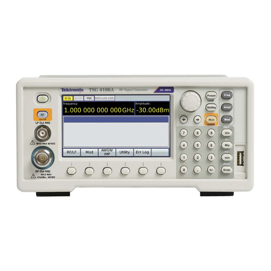
Operating basics Operating basics Front panel controls The following illustration shows the instrument front panel. The table describes the controls and elements noted in the illustration. Front panel TSG4100A Series RF Signal Generators User Manual... -
Page 27: Connectors
Operating basics Item Control element or number group Description Power button Press to turn power on or off. The power button has two modes: STANDBY and ON. In STANDBY mode, power is only supplied to the internal timebase and the power consumption will not exceed 20 W once the instrument is warmed up. -
Page 28: Table 1: Front Panel Connectors
±5 V. RF Output Type N output. Active for frequency settings between 950 kHz and 2 GHz (TSG4102A), 950 kHz and 4 GHz (TSG4104A), and 950kHz and 6 GHz (TSG4106A). The output power may be set from −110 dBm to 16.5 dBm (0.7 μV... -
Page 29: Table 2: Rear Panel Connectors
Operating basics Rear panel connectors Table 2: Rear panel connectors Item Connector Description AC power (input) Connect the unit to a power source through the power cord provided with the instrument. The center pin is connected to the chassis so that the entire box is earth grounded. The unit will operate with an AC input from 100 to 240 V , and with a frequency of 50/60 Hz. - Page 30 Operating basics Table 2: Rear panel connectors (cont.) Item Connector Description ANALOG MOD IN External analog modulation is applied to this input. The input impedance is 100 kΩ with a selectable input coupling of either DC or AC (4 Hz roll off). For analog modulations (AM, FM, ΦM), a signal of ±1 V will produce a full scale modulation of the output (depth for AM or deviation for FM and ΦM).
-
Page 31: Display, Navigation, And Menus
Operating basics Display, navigation, and menus Controls and display elements are shown in the following illustrations and tables. Display The display screen is divided into the following four sections: Display area function Description number Status Indicates instrument status. When an item is highlighted yellow or is displayed with bold typeface, that feature is active. -
Page 32: Table 3: Menus
Operating basics Navigation Navigate the Menus and Settings areas of the display by using the arrow keys (left, right), general knob (up, down, and push in knob to select), and Enter key (select). When a parameter is selected in the Settings area, you can use the arrow keys to select a digit, the number keys to enter a value, and the Enter key to make a selection. - Page 33 Operating basics Table 3: Menus (cont.) Menu Description Mod Type submenus: Analog, Vector, Presets. Constellation menu. This is a Mod submenu. It is available when the appropriate modulation type is active. The items in this menu vary depending on the active modulation type.
- Page 34 Operating basics Table 3: Menus (cont.) Menu Description Source menu. This is a Mod submenu. It is available when the appropriate modulation type is active. The items in this menu vary depending on the active modulation type. Filter menu. This is a Mod submenu. It is available when the appropriate modulation type is active.
- Page 35 Operating basics Table 3: Menus (cont.) Menu Description I/O Interface menu. This is a Utility submenu. RS232 menu and settings. This is an I/O Interface submenu. GPIB menu and settings. This is an I/O Interface submenu. This requires the instrument have the GPIB option.
- Page 36 Operating basics Table 3: Menus (cont.) Menu Description LAN menu, submenus, and settings. This is an I/O Interface submenu. System menu. This is a Utility submenu. Allows you to set display backlight, date, time, run a self test, and remove private data (Secure). Secure setting.
- Page 37 Operating basics Table 3: Menus (cont.) Menu Description File menu. This is a Utility submenu. It allows you to access saved files such as waveform, constellation, filter, and setup files. Available files will show in the Settings area of the display when you select the file type.
- Page 38 Operating basics Table 3: Menus (cont.) Menu Description About menu. This is a Utility submenu. It shows the instrument firmware version, installed options, instrument serial number in the Settings area. License Manage menu. This is an About submenu. It allows you to enter option/software keys to activate options.
-
Page 39: Quick Start And Functional Check
Quick start and functional check This section is intended to help first time users get started using a Tektronix TSG4100A Series RF Signal Generator and to help verify that the instrument is functioning correctly. -
Page 40: Table 4: Preset Default Settings
Operating basics Set default settings (Preset To set the instrument to the factory default settings without affecting saved presets, press and hold the Preset button on the front panel for three seconds. The button) following table shows some of the default settings that will be loaded. Table 4: Preset default settings Setting Default value... - Page 41 Operating basics 1. Change the frequency to 5 MHz as follows: a. Press the Freq button on the front panel to select the Frequency parameter in the Quick View area. b. Press the 5 number key. c. Press the M/μ button to set the units to MHz. d.
- Page 42 Operating basics 4. Use the general knob to select Preset from the Mod Type menu. NOTE. Turn the general knob to highlight your selection. Press the general knob to select it. 5. Turn the general knob to highlight GSM and then press the Enter button to load the GSM preset.
-
Page 43: Settings
Operating basics Settings Frequency Pressing the Freq button allows you to adjust the carrier frequency of the front panel BNC (LF Out) and Type N (RF Out) outputs. A frequency can be entered in any of the following units: GHz, MHz, kHz, or Hz using the unit buttons on the front panel. -
Page 44: Presets
Operating basics Mod On/Off Modulation can be turned on and off by pressing the Mod button on the front panel. When the modulation is off, the Mod LED button on the front panel is extinguished and the MODON text on the display is grey. When modulation is on, the Mod LED button on the front panel is lit and MODON on the display is yellow. -
Page 45: Table 5: Modulation Presets
Operating basics Table 5: Modulation presets Preset Description AM Audio Analog AM modulation of an audio clip. FM Audio Analog FM modulation of an audio clip. NADC Vector modulation parameters used in North American Digital Cellular (NADC) communications. Vector modulation parameters used in Personal Digital Cellular (PDC) communications. -
Page 46: Modulation Sources
Operating basics Arbitrary waveform user You can save arbitrary waveforms to the generator. Select Utility > File > Setup to access the user setups menu. To recall a setup, navigate to the desired setup presets number in the menu and then press Recall. You can also select to access files from the USB device and to save to a specific location. - Page 47 Operating basics The rear panel external modulation input supports bandwidths of 500 kHz, but the modulation bandwidth is limited to 100 kHz for fc greater than 62.5 MHz (93.75 MHz for the TSG4106A). The sensitivity is set such that a 1 V signal results in a full scale deviation (depth) in the output.
- Page 48 Operating basics Pulse Noise modulation For pulse modulation, the noise source is a Pseudo Random Binary Sequence (PRBS). The bit period is set using the Period setting in the Mod menu. The PRBS supports bit lengths of 2n, for 5 ≤ n ≤ 32 which correspond to a noise periodicity from 31 to 4,294,967,295 periods.
- Page 49 Operating basics Modulation outputs The rear panel Analog and Vector Mod Out BNCs provide a copy of the modulation function with ±1 V full scale range. This output will be a sine, ramp, triangle, square wave, pulse or noise depending on the selected internal modulation function.
-
Page 50: Table 6: Tsg4102A And 4104A Fm Modulation Vs. Frequency
For the bands 2 to 8, the rates and bandwidths are similar. However, the deviation increases by a factor of two, from 1 to 64 MHz, for octaves 2 through 8. Table 6: TSG4102A and 4104A FM modulation vs. frequency Internal FM rate,... - Page 51 Operating basics Output BNC which shows the 100 kHz modulating waveform. The middle trace is the front panel BNC output, whose amplitude was set to 1 V . The bottom trace is from the front panel Type N output, whose amplitude was set to 2 V Phase modulation Phase modulation can use either the internal modulation generator or an external source.
-
Page 52: Error Log
Operating basics has its first zero at 2.40477, which suppresses the carrier to below -88 dB. Error log This instrument contains an error buffer that can store up to 20 error codes associated with errors encountered during power-on self tests, command parsing, or command execution. -
Page 53: Digital Communications
Digital communications The TSG4100A Series generators support two types of modulation: analog and vector. Analog modulation refers to the modulation of a scalar parameter of the carrier signal, such as amplitude, frequency, or phase. Vector modulation refers to the modulation of the vector characteristics (amplitude and phase) of the carrier signal. -
Page 54: Vector Modulation
Digital communications Vector modulation All TSG4100A Series generators include standard support for I/Q modulation on RF carriers between 400 MHz and 6.075 GHz. In addition, they feature a dual, arbitrary waveform generator operating at 125 MHz for baseband signal generation. The generator has built-in support for the most common vector modulation schemes: ASK, QPSK, DQPSK, π/4 DQPSK, 8PSK, FSK, CPM. - Page 55 Digital communications The transmission of digital data is straight forward. Like analog communication, information is encoded in a modulation of the amplitude, frequency, or phase of an RF carrier. However, unlike analog communications, only a finite number of modulated states are allowed. In binary phase shift key (BPSK) modulation, for example, only two phases are allowed.
- Page 56 Digital communications Susceptibility to noise As mentioned previously, digital constellations have a finite number of allowed states. A BPSK constellation, for instance, has only two allowed states: 0° and 180°. This property greatly enhances the robustness of digital communications in the face of noise.
- Page 57 Digital communications Pulse shaping filters Up to now, we have emphasized the fact that digital constellations have a finite number of allowed states, but we have not discussed how the signal transitions from one allowed state to the next. The simplest method would be to jump as quickly as possible from state to state.
- Page 58 Digital communications where sinc(x) = sin(πx)/(πx). The following figure shows the impulse response of the raised cosine filter for α = 1.0, α = 0.5, and α = 0.3. Notice that as α is reduced the impulse response lasts longer and extends over many symbols. Normally, this behavior would cause intersymbol interference.
- Page 59 Digital communications where all parameters have the same definitions as in the raised cosine filter. The previous graph shows the impulse response of the root-raised cosine filter for α = 1.0, α = 0.5, and α = 0.3. The response is qualitatively similar to the raised cosine response, but it does not generally have zero ISI.
- Page 60 Digital communications with BT is the 3 dB bandwidth-symbol time product, a dimensionless factor similar to α in raised cosine filters that controls the bandwidth of the filter. The following graph shows the impulse response of the Gaussian filter for BT = 1.0, BT = 0.5, and BT = 0.3.
-
Page 61: Modulation Techniques
Digital communications Figure 1: Error vector magnitude Error vectors are helpful in characterizing the quality of a transmitted signal. They are a natural measure of the noise in a communications channel, but they can also help identify defects of a transmitter, such as amplifier compression or an IQ gain imbalance. -
Page 62: Figure 2: Ask Constellations
Digital communications Figure 2: ASK constellations FSK (frequency shift FSK is a modulation technique in which digital symbols are encoded in the frequency of the RF. The amplitude of the carrier is held constant. In the SG390 keying) series generators FSK is implemented using an internal rate generator followed by cosine/sine tables to convert a phase into its respective I and Q components. -
Page 63: Table 8: Vector Phase Modulation Waveforms
Digital communications PSK (phase shift keying) PSK is a modulation technique in which digital symbols are encoded in the phase of the RF. The amplitude of each constellation point is the same. In spite of this, the modulation is not constant amplitude as it is for FSK. The pulse shaping filters create amplitude variations as the modulation traverses from symbol to symbol, creating waveforms very similar to QAM. -
Page 64: Figure 4: Four Basic Psk Constellations
Digital communications Basic PSK constellations. The four basic PSK constellations are summarized in the following image. Note that the QPSK constellation follows a different mapping pattern than the 8 PSK and 16 PSK constellations. Since this constellation is identical to the QAM constellation of the same size, it uses the same mapping. Figure 4: Four basic PSK constellations CPM (continuous phase CPM is a form of FSK modulation. -
Page 65: Figure 5: Phase Trellis Diagram For Binary Cpm With A Rectangular Filter
Digital communications where T is the symbol period and N denotes the number of bits per symbol. Phase trellis diagram. As mentioned previously, CPM modulation is a form of continuous phase FSK. However, it can also be viewed as a special form of offset phase shift keying, OPSK, with sinusoidal symbol weighting. -
Page 66: Figure 6: Constellations For Qam 4 Through Qam 256
Digital communications Figure 6: Constellations for QAM 4 through QAM 256 MSK and GMSK Minimum shift keying (MSK) and Gaussian minimum shift keying (GMSK) are perhaps the two most well known examples of CPM modulation. MSK is binary CPM with a modulation index, h = 1/2, and a rectangular filter. It derives its name from the fact that the two frequencies of the modulation have the minimum frequency separation allowed for orthogonal detection. -
Page 67: Figure 7: Vsb Symbol Constellations
Digital communications VSB (vestigial sideband) Vestigial sideband modulation (VSB) is a form of amplitude modulation used in the over-the-air transmission of digital television (DTV) in the United States. Amplitude modulation normally creates two sidebands: an upper sideband and a lower sideband. However, the information content in the upper sideband is identical to that of the lower sideband. -
Page 68: Specialized Psk Constellations
Digital communications External IQ modulation The instrument can be modulated through an external source with bandwidths above 100 MHz. Rear panel BNC inputs are available as I and Q signal inputs. The inputs are terminated into 50 Ω with full-scale amplitude of 0.5 V. Note that an external vector modulation option is available for ASK, PSK, and QAM modulation modes. -
Page 69: Figure 9: Offset Modulation Prevents Transitions Through The Origin
Digital communications Offset or staggered This type of modulation addresses transmitter problems in the communication design. RF amplifiers can be made to operate more efficiently if the signals they modulation are amplifying are nearly constant in amplitude. This is especially important for satellites deployed in space. -
Page 70: Figure 10: Π/4 Dqpsk Uses Differential Encoding And A Rotating Constellation
Digital communications Figure 10: π/4 DQPSK uses differential encoding and a rotating constellation. Like DQPSK, π/4 DQPSK employs differential encoding, which means information is encoded in the change in phase, rather than the phase itself. However, the constellation for π/4 DQPSK rotates by 45° or π/4 radians after each symbol transmission. -
Page 71: Modulation Functions
Digital communications Modulation functions The modulation functions available for the vector function subtype are similar to those offered for analog modulation: sine, ramp, triangle, square, noise, user, and external. For the digital modulation subtypes, the available waveforms include: PRBS data, pattern data, and user data. PRBS data This instrument can generate pseudo random binary sequences (PRBS) for use with digital modulation subtypes. - Page 72 Digital communications Table 10: PRBS generating polynomials (cont.) Length Polynomial Pattern data Digital modulation subtypes can also be modulated with 16-bit patterns. The current pattern is shown as hexadecimal digits. Once selected, the pattern may be edited from the front panel by modifying each hexadecimal digit. The default pattern is the binary sequence 01010101 01010101, which corresponds to the hexadecimal value 0x5555.
-
Page 73: User Waveforms, Constellations, And Filters
User waveforms, constellations, and filters User waveforms, constellations, and filters This generator provides a broad array of built-in support for the most common digital modulation formats, constellations, and filters. However, you may choose to download custom waveforms, constellations, and filters over the remote interface if the built-in support does not match your needs. -
Page 74: Using The File Assistant Utility Software
Raw Socket Interface is not currently supported in the March 31, 2015 software version. Download TSG File The TSG File Assistant utility software is available for download at www.tek.com/downloads. To download the software, do the following: Assistant 1. Go to www.tektronix.com/downloads. 2. Select Software. TSG4100A Series RF Signal Generators User Manual... - Page 75 User waveforms, constellations, and filters 3. Enter TSG File Assistant in the search field. 4. When the search results appear, select TSG4k File Assistant and follow the instructions to download and install the software. TSG4100A Series RF Signal Generators User Manual...
- Page 76 User waveforms, constellations, and filters Load or convert an existing The following procedure shows you how to load a supported file (*.tsw, *.tsf, and *.tsc) or convert an unsupported file and send it to the instrument. file to the instrument 1.
- Page 77 User waveforms, constellations, and filters 6. A dialog box will appear. In this box, select a number from the User Number drop down menu. This number will determine where the file will be saved in the generator. For example, if you select 0, then the new file will be saved to the location in the generator that is associated with that User Number.
- Page 78 User waveforms, constellations, and filters 3. To check the ID of the instrument you are going to connect to, click the IDN? button. The instrument name will appear in the Message field. 4. Do one of the following: If you selected the GPIB interface, enter the GPIB address in the GPIB Address field and then click Connect.
- Page 79 User waveforms, constellations, and filters c. Enter the offset value in the Offset field. Constellation. To create a new constellation file, do the following: a. Select New Constellation from the File menu. b. Click the Load Raw Data From File button to open the *.txt file containing the constellation data.
- Page 80 User waveforms, constellations, and filters Analog waveform. To create a new analog waveform file, do the following. a. Select New Analog Waveform from the File menu. b. Click the Load Raw Data From File button to open the *.txt file containing the waveform data.
- Page 81 User waveforms, constellations, and filters e. If you selected IQ Data, you do not need to enter anything after the data has loaded. NOTE. The raw data format should include number pairs that define a point. Points should be listed one per line, as shown in the following image. Once the data is loaded, you can also add or edit the data in the new waveform window.
-
Page 82: Arbitrary User Waveforms
NOTE. See the TSG4100A Series RF Signal Generator Programmer Manual for detailed information about remote programming commands. It is available for download at www.tektronix.com/manuals. NOTE. You can use the TGS File Assistant utility software to download supported file types of arbitrary user waveforms to the generator when it is connected to the Ethernet through a LAN connection. -
Page 83: User Constellations
User waveforms, constellations, and filters <arb data> contains the binary data representing the data and it must contain an even integer number of bytes. Waveforms have a minimum size of 16 bits and are played back from MSB to LSB. If a waveform does not end on a 16-bit boundary, the least significant bits of the last word in the waveform will be ignored. - Page 84 User waveforms, constellations, and filters The constellation RAM is accessed with a 9-bit address that is the concatenation of a (9 – N)-bit symbol set and an N-bit symbol. The address is computed from the current symbol and set with the equation: constellation address = (symbol + set ×...
-
Page 85: User Filters
User waveforms, constellations, and filters The points lie on a circle of constant amplitude. The radius of the circle is 32767. Thus, we can compute the IQ coordinates as shown in the following table. Table 12: QPSK constellation point computations Symbol Formula Value... - Page 86 User waveforms, constellations, and filters This instrument provides built-in support for several commonly used digital filters. You also have the option to download custom filters. The filters have 24 symbols of memory and are defined with an oversampling ratio of 128, which means they are composed of 24 ×...
-
Page 87: Reference
Reference Reference Phase noise and offset diagrams TSG4100A Series RF Signal Generators User Manual... -
Page 88: Figure 13: Qpsk,3.840Mcps, 1.85 Ghz, 0Dbm), Rms Evm: 1.7
Reference Figure 13: QPSK,3.840Mcps, 1.85 GHz, 0dBm), RMS EVM: 1.7% TSG4100A Series RF Signal Generators User Manual... -
Page 89: Figure 14: Image 2, Qpsk,3.840Mcps, 1.85 Ghz, 0Dbm), Rms Evm: 1.7
Reference Figure 14: Image 2, QPSK,3.840Mcps, 1.85 GHz, 0dBm), RMS EVM: 1.7% TSG4100A Series RF Signal Generators User Manual... -
Page 90: Figure 15: Option Vm03 W-Cdma, (Qpsk,3.840Mcps, 2.1425Ghz, 0Dbm), Rms Evm: 1.7
Reference Figure 15: Option VM03 W-CDMA, (QPSK,3.840Mcps, 2.1425GHz, 0dBm), RMS EVM: 1.7% TSG4100A Series RF Signal Generators User Manual... -
Page 91: Figure 16: Image 2, Option Vm03 W-Cdma, (Qpsk,3.840Mcps, 2.1425Ghz, 0Dbm), Rms Evm: 1.7
Reference Figure 16: Image 2, Option VM03 W-CDMA, (QPSK,3.840Mcps, 2.1425GHz, 0dBm), RMS EVM: 1.7% TSG4100A Series RF Signal Generators User Manual... -
Page 92: Figure 17: Option Vm04 Apco-25, (4Fsk-C4Fm,4.8Ks/S,850Mhz, 0Dbm), Freq Err: 0.5
Reference Figure 17: Option VM04 APCO-25, (4FSK-C4FM,4.8KS/s,850MHz, 0dBm), Freq Err: 0.5% TSG4100A Series RF Signal Generators User Manual... -
Page 93: Figure 18: Option Vm05 Dect, (2Fsk1.152Mbps,1.925Ghz, 0Dbm), Rms Fsk Err: 1.5
Reference Figure 18: Option VM05 DECT, (2FSK1.152Mbps,1.925GHz, 0dBm), RMS FSK Err: 1.5% TSG4100A Series RF Signal Generators User Manual... -
Page 94: Figure 19: Option Vm06 Nadc, (Π/4 Dqpsk,24.3Ks/S,875Mhz, 0Dbm), Rms Evm: 0.3
Reference Figure 19: Option VM06 NADC, (π/4 DQPSK,24.3KS/s,875MHz, 0dBm), RMS EVM: 0.3% TSG4100A Series RF Signal Generators User Manual... -
Page 95: Figure 20: Option Vm07 Pdc, (Π/4 Dqpsk,21Ks/S, 800Mhz,0Dbm), Rms Evm: 0.6
Reference Figure 20: Option VM07 PDC, (π/4 DQPSK,21KS/s, 800MHz,0dBm), RMS EVM: 0.6% TSG4100A Series RF Signal Generators User Manual... -
Page 96: Figure 21: Option Vm08 Tetra, (Π/4 Dqpsk,18Ks/S, 420Mhz, 0Dbm), Rms Evm: 0.7
Reference Figure 21: Option VM08 TETRA, (π/4 DQPSK,18KS/s, 420MHz, 0dBm), RMS EVM: 0.7% TSG4100A Series RF Signal Generators User Manual... - Page 97 15 digital constellations, 46 save image of display as, 15 Documentation, x FSK (frequency shift keying), 46 BNC, 15 Tektronix part numbers, 1 Functional check, 24 Downloading files TSG File Assistant, 58 Cable, 1 Gaussian Cleaning procedures, 9 filter, 43...
- Page 98 Index Menus, 15, 16 Modulation deviation, 56 About, 22 Modulation index, 50 Help, x analog, modulation type, 17 Modulation presets, 28 AWGN/IMP, 18 Modulation rate, 56 Constellation, 17 Modulation technique Incoming inspection, 8 Customized filters, 18 ASK, 45 Index Customized source, 18 AWGN, 51 modulation, 50 Error code, 23...
- Page 99 Index Phase, 27 RF button, 27 Symbol clock, 13 modulation, 35 RF Out, 27 Phase trellis diagram Root-raised cosine CPM, 49 filter, 42 Time Power Rotating constellations, 53 setting, 20 AC, 13 RS-232, 5, 14 Timebase, 14 removing, 7 TSG File Assistant software, 1, Power (AWGN), 28 Power cord options, 1 Save...
Need help?
Do you have a question about the TSG4102A and is the answer not in the manual?
Questions and answers