Table of Contents
Advertisement
Quick Links
HPE MSA 1050 User Guide
Abstract
This document describes initial hardware setup for HPE MSA 1050 controller enclosures, and is intended for use by
storage system administrators familiar with servers and computer networks, network administration, storage system
installation and configuration, storage area network management, and relevant protocols.
Firmware Version: VE270
Part Number: Q1J79-62038
Published: February 2020
Edition: 1
Advertisement
Table of Contents
Troubleshooting

Related Manuals for HPE MSA 1050


Summary of Contents for HPE MSA 1050
- Page 1 HPE MSA 1050 User Guide Abstract This document describes initial hardware setup for HPE MSA 1050 controller enclosures, and is intended for use by storage system administrators familiar with servers and computer networks, network administration, storage system installation and configuration, storage area network management, and relevant protocols.
- Page 2 Adobe® and Acrobat® are trademarks of Adobe Systems Incorporated. Java and Oracle are registered trademarks of Oracle and/or its affiliates. UNIX® is a registered trademark of The Open Group. Revision History Q2R18-62010 September 2017 Initial HPE release. Q1J79-62022 July 2018 Updated release information. February 2020 Q1J79-62038 Updated power supply and user login/password information.
-
Page 3: Table Of Contents
Connecting the MSA 1050 controller to the LFF or SFF drive enclosure ...... - Page 4 Preparing a Windows computer for cabling to the CLI port ..........33 Obtaining IP values .
- Page 5 MSA 1050 Array SFF or supported 24-drive expansion enclosure....... . .
- Page 6 10 Cabling connections between the MSA 1050 controller and a single drive enclosure ......20...
- Page 7 Tables 1 Related MSA firmware documentation ............... 9 2 Installation checklist .
-
Page 8: Overview
“MSA 1050 controller module—rear panel LEDs” (page 62) The MSA 1050 enclosures support virtual storage. For virtual storage, a group of disks with an assigned RAID level is called a virtual disk group. This guide uses the term disk group for brevity. -
Page 9: Features And Benefits
Product QuickSpecs Check the QuickSpecs for a complete list of supported servers, operating systems, disk drives, and options. See https://www.hpe.com/support/MSA1050QuickSpecs. If a website location has changed, an Internet search for “HPE MSA 1050 quickspecs” will provide a link. Related MSA documentation Related support information is provided in the “Support and other resources”... -
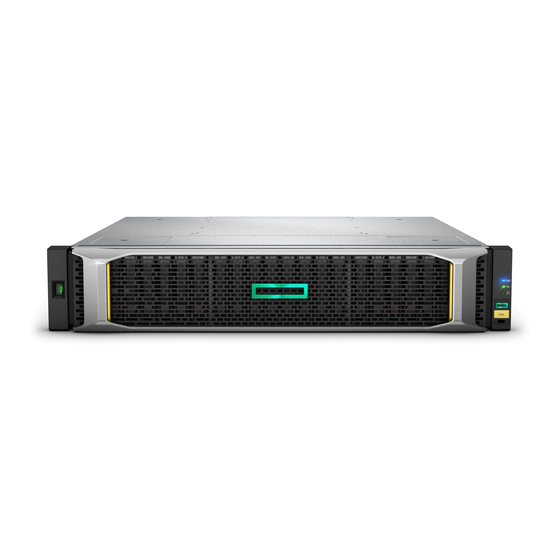
Page 10: Components
HPE MSA 1050 models use either an enclosure bezel or traditional ear covers. The 2U bezel assembly is comprised of left and right ear covers connected to the bezel body subassembly. A sample bezel is shown below. -
Page 11: Msa 1050 Array Lff Or Supported 12-Drive Expansion Enclosure
Disk drives used in MSA 1050 enclosures MSA 1050 enclosures support LFF/SFF Midline SAS and LFF/SFF Enterprise SAS disks, and LFF/SFF SSDs. For information about creating disk groups and adding spares using these different disk drive types, see the SMU Reference Guide. -
Page 12: Controller Enclosure-Rear Panel Layout
The diagrams with tables that immediately follow provide descriptions of the different controller modules and power supply modules that can be installed into the rear panel of an MSA 1050 controller enclosure. Showing controller modules and power supply modules separately from the enclosure provides improved clarity in identifying the component items called out in the diagrams and described in the tables. -
Page 13: Msa 1050 Controller Module-Rear Panel Components
(Sticker shown covering the opening) Reserved for future use SAS expansion port Network management port Figure 5 MSA 1050 controller module face plate (FC or 10GbE iSCSI) Figure 6 shows a 1 Gb iSCSI (RJ-45) controller module. = FC LEDs... -
Page 14: Drive Enclosures
MSA 1050 controller enclosures support adding the 6 Gb drive enclosures described below. LFF and SFF drive enclosure — rear panel layout MSA 1050 controllers support the MSA 2050 LFF Disk Enclosure and the MSA 2050 SFF Disk Enclosure, which share the same rear panel layout, as shown below. -
Page 15: Cache
(Midplane-facing rear view) CompactFlash memory card Figure 9 MSA 1050 CompactFlash memory card If one controller fails, then later another controller fails or does not start, and the Cache Status LED is on or blinking, the CompactFlash will need to be transported to a replacement controller to recover data not flushed to disk (see “Controller... -
Page 16: Supercapacitor Pack
Supercapacitor pack To protect RAID controller cache in case of power failure, MSA 1050 controllers are equipped with supercapacitor technology, in conjunction with CompactFlash memory, built into each controller module to provide extended cache memory backup time. -
Page 17: Installing The Enclosures
38). See the SMU Reference Guide or online help for additional information. Connecting controller and drive enclosures MSA 1050 controller enclosures support up to four enclosures (including the controller enclosure). You can cable drive enclosures of the same type or of mixed LFF/SFF model type. -
Page 18: Connecting The Msa 1050 Controller To The Lff Or Sff Drive Enclosure
Connecting the MSA 1050 controller to the LFF or SFF drive enclosure The MSA 2050 LFF Disk Enclosure and the MSA 2050 SFF Disk Enclosure can be attached to an MSA 1050 controller enclosure using supported mini-SAS to mini-SAS cables of 0.5 m (1.64') to 2 m (6.56') length [see Figure 10 (page 20)]. - Page 19 “Controller enclosure—rear panel layout” (page 12). IMPORTANT: MSA 1050 controller enclosures support dual-controller only. If a partner controller fails, the array will fail over and run on a single controller until the redundancy is restored. A controller module must be installed in each IOM slot to ensure sufficient airflow through the enclosure during operation.
-
Page 20: Cabling Connections Between The Msa 1050 Controller And A Single Drive Enclosure
Controller A Controller B = LFF 12-drive or SFF 24-drive enclosure Figure 10 Cabling connections between the MSA 1050 controller and a single drive enclosure Controller A Controller A Controller B Controller B In Out In Out In Out In Out... -
Page 21: Testing Enclosure Connections
NOTE: Power supplies used in MSA 1050 enclosures The MSA 1050 controller enclosures and drive enclosures are equipped with AC power supplies that do not have power switches (they are switchless). They power on when connected to a power source, and they power off when disconnected. -
Page 22: Ac Power Supply
1. Stop all I/O from hosts to the system [see “Stopping I/O” (page 41)]. 2. Shut down both controllers using either method described below: Use the SMU to shut down both controllers, as described in the online help and web-posted HPE MSA 1050/2050 SMU Reference Guide. Proceed to step Use the CLI to shut down both controllers, as described in the HPE MSA 1050/2050 CLI Reference Guide. -
Page 23: Connecting Hosts
Each controller module provides two host ports designed for use with an FC SFP supporting data rates up to 8 Gb/s. MSA 1050 FC controllers can also be cabled to support the optionally-licensed Remote Snap replication feature via the FC ports. - Page 24 CLI command to view information about host ports. 10GbE iSCSI protocol The MSA 1050 controller enclosures support two controller modules using the Internet SCSI interface protocol for host connection. Each controller module provides two host ports designed for use with a 10GbE iSCSI SFP or approved DAC cable supporting data rates up to 10 Gb/s, using either one-way or mutual CHAP (Challenge-Handshake Authentication Protocol).
-
Page 25: Host Connection Configurations
Remote Snap replication feature. To connect the MSA 1050 controller to a server or switch—using 10GbE iSCSI SFPs or approved DAC cables in controller ports—select the appropriate qualified 10GbE SFP option (see the QuickSpecs). Such cables are also used for connecting a local storage system to a remote storage system via a switch, to facilitate use of the optional Remote Snap replication feature. -
Page 26: Connecting Direct Attach Configurations
Connecting direct attach configurations MSA 1050 controller enclosures support dual-controller only. If a partner controller fails, the array will fail over and run on a single controller until the redundancy is restored. A controller module must be installed in each IOM slot to ensure sufficient airflow through the enclosure during operation. -
Page 27: Connecting Switch Attach Configurations
The management host directly manages systems out-of-band over an Ethernet network. 1. Connect an RJ-45 Ethernet cable to the network management port on each MSA 1050 controller. 2. Connect the other end of each Ethernet cable to a network that your management host can access (preferably on the same subnet). -
Page 28: Connecting Two Storage Systems To Replicate Volumes
Replication configuration possibilities are many, and can be cabled—in switch attach fashion—to support MSA 1050 FC and iSCSI systems on the same network, or on different networks (MSA 1050 SAS systems do not support replication). As you consider the physical connections of your system—specifically connections for replication—keep several important points in mind: •... -
Page 29: Cabling For Replication
IMPORTANT: MSA 1050 controller enclosures support dual-controller configuration only. A controller module must be installed in each IOM slot to ensure sufficient airflow through the enclosure during operation. Each of the following diagrams show the rear panel of two MSA 1050 FC or iSCSI controller enclosures equipped with dual-controller modules. -
Page 30: Updating Firmware
Figure 18 Connecting two storage systems for Remote Snap: multiple servers/switches/one location Multiple servers/different networks/multiple switches The diagram below shows the rear panel of two MSA 1050 controller enclosures with both I/O and replication occurring on different networks. Peer sites with failover... - Page 31 • HPE recommends that Partner Firmware Update is enabled (the default setting). Optionally, you can update firmware using SFTP or FTP as described in the SMU Reference Guide. IMPORTANT: See the topics about updating firmware within the SMU Reference Guide before performing a firmware update.
-
Page 32: Connecting To The Controller Cli Port
Device description The MSA 1050 controllers feature a command-line interface port used to cable directly to the controller and initially set IP addresses, or perform other configuration tasks. This port employs a mini-USB Type B form factor, requiring a cable that is supplied with the controller, and additional support described herein, so that a server or other computer running a Linux or Windows operating system can recognize the controller enclosure as a connected device. -
Page 33: Preparing A Windows Computer For Cabling To The Cli Port
Obtaining IP values One method of obtaining IP values for your system is to use a network management utility to discover “HPE MSA Storage” devices on the local LAN through SNMP. Alternative methods for obtaining IP values for your system are described in the following subsections. - Page 34 Network ports on controller module A and controller module B are configured with the following factory-default IP settings: • Management Port IP Address: 10.0.0.2 (controller A), 10.0.0.3 (controller B) • IP Subnet Mask: 255.255.255.0 • Gateway IP Address: 10.0.0.1 If the default IP addresses are not compatible with your network, you must set an IP address for each network port using the command-line interface.
-
Page 35: Terminal Emulator Display Settings
Enter your password. IMPORTANT: As of MSA firmware version VE270P003 (MSA 1050) and VL270P003 (MSA 2050 and MSA 2052), the MSA systems no longer support the default user name and password for logging into the system. After upgrading to this firmware version, you will be prompted to create a new user name and password combination using the setup user account. - Page 36 2 page NOTE: If using a Windows operating system version older than Windows 10/Server 2016, access the USB device driver download from the HPE MSA support website at https://www.hpe.com/support/downloads. Connecting to the controller CLI port...
-
Page 37: Using The Cli Port And Cable-Known Issues On Windows
Using the CLI port and cable—known issues on Windows When using the CLI port and cable for setting controller IP addresses and other operations, be aware of the following known issues on Microsoft Windows platforms. Problem On Windows operating systems, the USB CLI port may encounter issues preventing the terminal emulator from reconnecting to storage after the Management Controller (MC) restarts or the USB cable is unplugged and reconnected. -
Page 38: Basic Operation
This brief sign in process assumes proper web browser setup. IMPORTANT: As of MSA firmware version VE270P003 (MSA 1050) and VL270P003 (MSA 2050 and MSA 2052), the MSA systems no longer support the default user name and password for logging into the system. After upgrading to this firmware version, you will be prompted to create a new user name and password combination using the setup user account. -
Page 39: Troubleshooting
USB CLI port connection MSA 1050 controllers feature a CLI port employing a mini-USB Type B form factor. If you encounter problems communicating with the port after cabling your computer to the USB device, you may need to either download a device driver (Windows), or set appropriate parameters via an operating system command (Linux). -
Page 40: Performing Basic Steps
Use the CLI As an alternative to using the SMU, you can run the show system command in the CLI to view the health of the system and its components. If any component has a problem, the system health will be Degraded, Fault, or Unknown, and those components will be listed as Unhealthy Components. -
Page 41: If The Enclosure Does Not Initialize
For information about specific events, see the Event Descriptions Reference Guide, located on the Hewlett Packard Enterprise Information Library at: https://www.hpe.com/support/msa1050. The event logs record all system events. It is very important to review the logs, not only to identify the fault, but also to search for events that might have caused the fault to occur. -
Page 42: Diagnostic Steps
See the CLI Reference Guide for additional information on the Hewlett Packard Enterprise Information Library at: https://www.hpe.com/support/msa1050. Diagnostic steps This section describes possible reasons and actions to take when an LED indicates a fault condition during initial system setup. -
Page 43: Is The Enclosure Rear Panel Fru Ok Led Off
The disk is offline. • The disk is not configured. NOTE: See “Disk drives used in MSA 1050 enclosures” (page 11). Is the disk drive module Fault/UID LED blinking amber? Table 11 Diagnostics LED status: Front panel disks “Fault/UID” Answer... -
Page 44: Is A Connected Host Port Host Link Status Led Off
Table 11 Diagnostics LED status: Front panel disks “Fault/UID” (continued) Answer Possible reasons Actions Yes, and the The disk drive is offline. A predictive • Check the event log for specific information regarding the fault. Online/Activity failure alert may have been received for •... -
Page 45: Is A Connected Port Network Port Link Status Led Off
Is a connected port Network Port Link Status LED off? Table 14 Diagnostics LED status: Rear panel “Network Port Link Status” Answer Possible reasons Actions System functioning properly. No action required. The link is down. Use standard networking troubleshooting procedures to isolate faults on the network. -
Page 46: If The Controller Has Failed Or Does Not Start, Is The Cache Status Led On/Blinking
Host-side connection troubleshooting featuring host ports with SFPs The procedure below applies to MSA 1050 controller enclosures employing small form factor pluggable (SFP) transceiver connectors in 8 Gb FC, 10GbE iSCSI, or 1 Gb iSCSI host interface ports. In the following procedure, “SFP and host cable” is used to refer to FC or iSCSI controller ports used for I/O or replication. - Page 47 1. Halt all I/O to the storage system as described in “Stopping I/O” (page 41). 2. Check the host link status/link activity LED. If there is activity, halt all applications that access the storage system. 3. Check the Cache Status LED to verify that the controller cached data is flushed to the disk drives. Solid –...
-
Page 48: Isolating A Controller Module Expansion Port Connection Fault
Isolating a controller module expansion port connection fault During normal operation, when a controller module expansion port is connected to a drive enclosure, the expansion port status LED is green. If the connected port’s expansion port LED is off, the link is down. Use the following procedure to isolate the fault. -
Page 49: Replication Setup And Verification
See HPE MSA 1050/2050 CLI Reference Guide for replication commands and syntax • See HPE MSA Event Descriptions Reference Guide for replication event reporting Basic information for enabling the MSA 1050 FC or iSCSI controller enclosures for replication supplements the troubleshooting procedures that follow. •... -
Page 50: Diagnostics For Replication Setup: Using Remote Snap Feature
Can you successfully use the Remote Snap feature? Answer Possible reasons Actions System functioning properly. No action required. Remote Snap is not licensed on each Verify licensing of the optional feature per system: controller enclosure used for replication. • In the Home topic in the SMU, select Action > Install License. •... -
Page 51: Diagnostics For Replication Setup: Replicating A Volume
Answer Possible reasons Actions Communication link is down. Review event logs for indicators of a specific fault in a host or replication data path component. After ensuring valid licensing, valid cabling connections, and network availability, create the replication set using the Replications topic; select Action >... -
Page 52: Resolving Voltage And Temperature Warnings
5. Try replacing each power supply module one at a time. 6. Replace the controller modules one at a time. 7. Replace SFPs one at a time (MSA 1050 FC or iSCSI storage systems). Sensor locations The storage system monitors conditions at different points within each enclosure to alert you to problems. Power, cooling fan, temperature, and voltage sensors are located at key points in the enclosure. -
Page 53: Temperature Sensors
During a shutdown, the cooling fans do not shut off. This allows the enclosure to continue cooling. Temperature sensors Extreme high and low temperatures can cause significant damage if they go unnoticed. When a temperature fault is reported, it must be remedied as quickly as possible to avoid system damage. This can be done by warming or cooling the installation location. -
Page 54: Support And Other Resources
IMPORTANT: Access to some updates might require product entitlement when accessed through the Hewlett Packard Enterprise Support Center. You must have an HPE Passport set up with relevant entitlements. Remote support Remote support is available with supported devices as part of your warranty or contractual support agreement. It provides intelligent event diagnosis, and automatic, secure submission of hardware event notifications to Hewlett Packard Enterprise, which will initiate a fast and accurate resolution based on your product’s service level. -
Page 55: Remote Support And Proactive Care Information
HPE Proactive Care services https://www.hpe.com/services/proactivecare HPE Datacenter Care services https://www.hpe.com/services/datacentercare HPE Proactive Care service: Supported products list https://www.hpe.com/services/proactivecaresupportedproducts HPE Proactive Care advanced service: Supported products list https://www.hpe.com/services/proactivecareadvancedsupportedproducts Proactive Care customer information Proactive Care central https://www.hpe.com/services/proactivecarecentral Proactive Care service activation https://www.hpe.com/services/proactivecarecentralgetstarted Warranty information To view the warranty for your product, see the links provided below. -
Page 56: Additional Regulatory Information
Hewlett Packard Enterprise is committed to providing documentation that meets your needs. To help us improve the documentation, send any errors, suggestions, or comments to Documentation Feedback (docsfeedback@hpe.com). When submitting your feedback, include the document title, part number, edition, and publication date located on the front cover of the document. -
Page 57: Aled Descriptions
Front panel LEDs HPE MSA 1050 models support small form factor (SFF) and large form factor (LFF) enclosures. The SFF chassis, configured with 24 2.5" SFF disks, is used as a controller enclosure or drive enclosure. The LFF chassis, configured with 12 3.5"... -
Page 58: Msa 1050 Array Sff Or Supported 24-Drive Expansion Enclosure
Off — Both power supplies are off; the system is powered off. Fault ID Amber — Fault condition exists. The event has been identified, but the problem needs attention. Off — No fault condition exists. Figure 23 LEDs: MSA 1050 Array SFF or supported 24-drive expansion enclosure: front panel LED descriptions... -
Page 59: Msa 1050 Array Lff Or Supported 12-Drive Expansion Enclosure
Amber — Fault condition exists. The event has been identified, but the problem needs attention. Off — No fault condition exists. Figure 24 LEDs: MSA 1050 Array LFF or supported 12-drive expansion enclosure: front panel Ear covers Ear covers can be used instead of the enclosure bezel. -
Page 60: Disk Drive Leds
Disk drive LEDs 3.5" LFF disk drive Disk drive LED key: 2.5" SFF disk drive = Fault/UID (amber/blue) (sled grate is not shown) = Online/Activity (green) Online/Activity (green) Fault/UID (amber/blue) Description Normal operation. The disk drive is online, but it is not currently active. -
Page 61: Rear Panel Leds
The diagrams with tables that immediately follow provide descriptions of the different controller modules and power supply modules that can be installed into the rear panel of an MSA 1050 controller enclosure. The controller module for your product is pre-configured with the appropriate external connector for the selected host interface protocol. Showing controller modules and power supply modules separately from the enclosure provides improved clarity in identifying the component items called out in the diagrams and described in the tables. -
Page 62: Leds: Msa 1050 Controller Module (Fc Or 10Gbe Models)
When powering up and booting, iSCSI LEDs will be on/blinking momentarily, then they will switch to the mode of operation. When port is down, both LEDs are off. Figure 28 LEDs: MSA 1050 controller module (FC or 10GbE models) LED descriptions... -
Page 63: Leds: Msa 1050 Controller Module (1 Gb Rj-45 Models)
When powering up and booting, iSCSI LEDs will be on/blinking momentarily, then they will switch to the mode of operation. When port is down, both LEDs are off. Figure 29 LEDs: MSA 1050 controller module (1 Gb RJ-45 models) When port is down, both LEDs are off. -
Page 64: Cache Status Led - Power On Behavior
NOTE: Once a Link Status LED is lit, it remains so, even if the controller is shutdown via the SMU or CLI. When a controller is shutdown or otherwise rendered inactive—its Link Status LED remains illuminated—falsely indicating that the controller can communicate with the host. Though a link exists between the host and the chip on the controller, the controller is not communicating with the chip. - Page 65 Amber — Voltage (input or output), Current, Temperature is out of range Fault/Service Required or fan failure. Off — Output voltage is normal. Figure 31 LEDs: MSA 1050 Storage system enclosure power supply modules NOTE: See “Powering on/powering off” (page 21) for information about power-cycling enclosures.
-
Page 66: Lff And Sff Drive Enclosures-Rear Panel Layout
MSA 1050 controllers support the 3.5" 12-drive enclosure and the 2.5" 24-drive enclosure for adding storage. The front panel of the 12-drive enclosure looks identical to the MSA 1050 Array LFF front panel. The front panel of the 24-drive enclosure looks identical to the MSA 1050 Array SFF front panel. The rear panel of the MSA 2050 LFF Disk Enclosure (12-drive) and the MSA 2050 SFF Disk Enclosure (24-drive) enclosures are identical, as shown below. -
Page 67: B Specifications And Requirements
(such as air conditioning motors, elevator motors, and factory loads). NOTE: For power requirements, see the QuickSpecs: https://www.hpe.com/support/MSA1050QuickSpecs. If a website location has changed, an Internet search for “HPE MSA 1050 quickspecs” will provide a link. Weight and placement guidelines Refer to “Physical requirements”... -
Page 68: Electrical Guidelines
Electrical guidelines • These enclosures work with single-phase power systems having an earth ground connection. To reduce the risk of electric shock, do not plug an enclosure into any other type of power system. Contact your facilities manager or a qualified electrician if you are not sure what type of power is supplied to your building. -
Page 69: Environmental Requirements
Table 29 provides weight data for MSA 1050 controller enclosures and drive enclosures. For information about other HPE MSA drive enclosures that may be cabled to these systems, check the QuickSpecs at: https://www.hpe.com/support/MSA1050QuickSpecs. If a website location has changed, an Internet search for “HPE MSA 1050 quickspecs”... -
Page 70: Electrical Requirements
(UPS). IMPORTANT: See the QuickSpecs for information about power cables provided with your MSA 1050 Storage product. If a website location has changed, an Internet search for “HPE MSA 1050 quickspecs” will provide a link. -
Page 71: C Electrostatic Discharge
Electrostatic discharge Preventing electrostatic discharge To prevent damaging the system, be aware of the precautions you need to follow when setting up the system or handling parts. A discharge of static electricity from a finger or other conductor may damage system boards or other static-sensitive devices. -
Page 72: Dsas Fan-Out Cable Option
SAS fan-out cable option Locate the SAS fan-out cable Locate the appropriate qualified SAS fan-out cable option for your MSA 1050 SAS controller module. Qualified fan-out cable options are briefly described in “Cable requirements for MSA 1050 enclosures” (page 18). -
Page 73: Index
70 memory card 15 input voltage requirement 70 transporting 46 installation checklist 17 components site requirements 68 MSA 1050 troubleshooting 41 enclosure front panel web-browser based configuring and provisioning 38 LFF enclosure 11 weight 69 SFF enclosure 10... - Page 74 Heartbeat 58 locating 52 Unit Identification (UID) 58 power supply 52 enclosure rear panel temperature 53 MSA 1050 voltage 53 10GbE iSCSI Host Link Status/Link Activity 62 site planning 1Gb iSCSI Host Link Status/Link Activity 63 EMC 67 Cache Status 62...
- Page 75 troubleshooting 39 controller failure, single controller configuration 45 correcting enclosure IDs 41 enclosure does not initialize 41 expansion port connection fault 48 host-side connection fault 46 Remote Snap replication faults 48 using event notification 40 using system LEDs 42 using the CLI 40 using the SMU 39 ventilation requirements 68 warnings...
Need help?
Do you have a question about the MSA 1050 and is the answer not in the manual?
Questions and answers