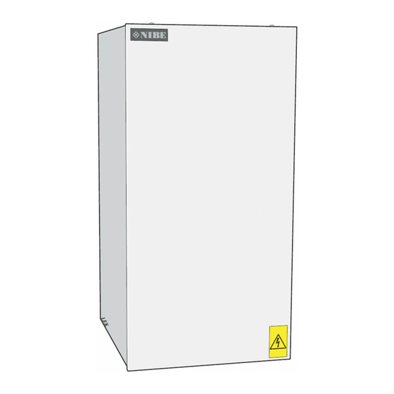
Nibe ELK 42 Installation And Maintenance Instructions Manual
Hide thumbs
Also See for ELK 42:
- Installer manual (52 pages) ,
- Installation and maintenance instructions manual (20 pages) ,
- Installer manual (49 pages)
Table of Contents
Advertisement
Quick Links
Advertisement
Table of Contents

Summary of Contents for Nibe ELK 42
- Page 1 MOS GB 1238-2 INSTALLATION AND MAINTENANCE INSTRUCTIONS ELK 42 ELK 42 231253...
-
Page 3: Table Of Contents
FIGHTER 1320/1330 and F1330 System diagram F1345 Operation and maintenance Miscellaneous General Operation Electrical circuit diagram Safety valve ELK 42 Venting Technical specifications Draining Dimensions Actions in the event of freeze risk Component positions List of components For the Installer... - Page 4 General In order to get the greatest benefit from the electric heater ELK 42 you should read the "For Home Owners" section in this Installation and Maintenance Instruction. ELK 42 is an electric heater that is intended for installation together with a heat pump for heating detached houses and small apartment buildings.
-
Page 5: For Home Owners
For Home Owners System description System description Principle of operation Components NIBE ELK 42 is an electric heater that is primarily intended Shut-off valve for installation together with a heat pump for heating Non-return valve buildings. Circulation pump ELK 42 contains overheat protection and contactors for ex- Expansion vessel ternal control of the three power groups, 6.0, 12.0 and 24.0... -
Page 6: Operation And Maintenance General
If a part of the heating system is thought to be frozen, con- tact the installer. If the heating system must be switched off for a long period of time, drain the water and ensure that the immersion heater cannot be started. ELK 42... -
Page 7: For The Installer
Electrical installation Area of use for NIBE immersion heater is in combination with ELK 42 must be installed via an isolator switch with a minim- NIBE ground source heat pumps and air/water heat pumps. um breaking gap of 3 mm. -
Page 8: Installation Alternative Components
GP10 Circulation pump, heating medium HQ1X Particle filter Auxiliary relay, immersion heater QM11 filler valve QM2X Venting valve QM30-QM59 Shut-off valve QN10 Reversing valve, hot water/heating RMXX Non-return valve RN11 Trim valve Connection box XL27-XL28 Connection, filling brine ELK 42... -
Page 9: Fighter 1320/1330 And F1330
B is also started. FIGHTER striction of the electrical power for 5 kW within 2 hours 1320/1330 / F1330 connects ELK 42 in steps when the energy from start-up is required. requirement exceeds the heat pump capacity. - Page 10 Electrical connection FIGHTER 1320/1330 Without thermostat, 2 active electrical steps 18 kW immersion heater step active. FIGHTER 1320/1330 ELK 42 FIGHTER 1320/1330 With thermostat, 3 active electrical steps 42 kW immersion heater step active. 24 kW immersion heater step active in emergency mode.
- Page 11 Electrical connection F1330 Without thermostat, 2 active electrical steps 18 kW immersion heater step active. F1330 ELK 42 F1330 With thermostat, 3 active electrical steps 42 kW immersion heater step active. 24 kW immersion heater step active in emergency mode.
-
Page 12: F1345
5.1.12 - step controlled add. pipe to the radiators. ELK 42 is connected automatically when heat. the energy requirement exceeds the heat pump capacity. - Page 13 Electrical connection F1345 Without thermostat, 3 active electrical steps 42 kW immersion heater step active. F1345 ELK 42 F1345 With thermostat, 3 active electrical steps 42 kW immersion heater step active. 24 kW immersion heater step active in emergency mode.
-
Page 14: Miscellaneous
Miscellaneous Electrical circuit diagram Electrical circuit diagram ELK 42 ELK 42... -
Page 15: Technical Specifications Dimensions
Miscellaneous Technical specifications Technical specifications Dimensions ELK 42... -
Page 16: Component Positions
Overheat protection (-B1) Miniature circuit-breaker Terminal block (-X9) Contactor (-K1) Contactor (-K2) Contactor (-K3) Contactor (-K4) Contactor (-K5) Emergency mode thermostat (-B2) Connection, flow line, G 40 Connection, return line, G 40 Cable grommet Venting Sign, serial number ELK 42... -
Page 17: Technical Specifications
63 A Enclosure class IP 44 Max permitted pressure in the 0.7 MPa (7 bar) boiler Max flow Min flow 1800 l/h Material immersion heater SIS 2333 EN 1.4301 Material tube SIS 2333 EN 1.4301 Part No. 067 075 ELK 42... -
Page 18: Dealing With Malfunctions
Reset by pressing in the button on the overheating protection, Work behind panels secured by screws may only be when the temperature has dropped below 80 °C. carried out by a qualified installation engineer. Circulation pump stopped. ELK 42... - Page 20 Puh: 09-274 697 0 Fax: 09-274 697 40 E-mail: info@nibe.fi www.nibe.fi AIT France, 10 rue des Moines, 67500 Haguenau Tel : 03 88 06 24 10 Fax : 03 88 06 90 15 E-mail: info@nibe.fr www.nibe.fr NIBE Energy Systems Ltd, 3C Broom Business Park, Bridge Way, Chesterfield S41 9QG Tel: 0845 095 1200 Fax: 0845 095 1201 E-mail: info@nibe.co.uk www.nibe.co.uk...


Need help?
Do you have a question about the ELK 42 and is the answer not in the manual?
Questions and answers