
Related Manuals for Nibe EVC 13


Summary of Contents for Nibe EVC 13
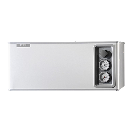
- Page 1 MOS GB 1538-2 INSTALLATION AND MAINTENANCE INSTRUCTIONS EVC 13 EVC 13 511291 °C...
-
Page 3: Table Of Contents
Max. thermostat Fuse and tariff kit for electrical supply of external electric Tariff control, (option) water heater Safety valve Room sensor Pressure gauge Temperature gauge Enclosed kit Operating fuse Technical specifications Rectifying any malfunctions Energy labelling Low room temperature EVC 13... -
Page 4: Removing The Cover
English Removing the cover Removing the cover EVC 13... -
Page 5: General
EVC 13 is a high quality electric boiler with a long service life, developed and made in Sweden for Swedish conditions. Serial number* (103), must always be stated in all correspondence with NIBE. -
Page 6: System Description General
English System description System description General Principle of operation EVC 13 has outdoor temperature controlled boiler temper- ature, which is why a shunt valve is not needed. Outdoor Explanation temperature sensor supplied. The power is connected and Outside sensor disconnected using two contactors and two relays. -
Page 7: Front Panel
Clock The immersion heater is restricted to 6 kW. Any The time for connecting and disconnecting of water heater connected is powered up. "Night reduction" is set on the clock, see also under "Switch" EVC 13... -
Page 8: Boiler Temperature
The gauge displays the present boiler temperature, which is the same as the supply temperature. Boiler pressure The system/boiler pressure is shown here. The gauge graduation is 0 – 4 bar. Normal pressure is 0.5 – 1.5 bar. EVC 13... -
Page 9: Settings
Warm weather conditions If the room temperature is too low, increase the “Offset heating curve” setting by one step clockwise. If the room temperature is too high, reduce the “Offset heating curve” setting by one step anti-clockwise. EVC 13... -
Page 10: Basic Values For The Automatic Heating Control
*** Under floor heating can be dimensioned very differently. Example 3 above refers 10 (5) Växjö 12 (6) to a system where the supply temperature needs to be approximately 35–40 °C on Halmstad Kalmar Markaryd the coldest day. Helsingborg Karlskrona Hässleholm Malmö Simrishamn Ystad 11 (5) Example EVC 13... -
Page 11: Offset Heating Curve -2
English Settings Offset heating curve -2 Setting after diagram EVC 13 is equipped with an outdoor temperature con- Supply temperature Heating curve trolled heating control system. This means the boiler • C temperature and therefore the supply temperature is regulated in relation to the current outdoor temperature. -
Page 12: Clock
The numbers around the display indicate the 24 hours of the day. One press: Night reduction activated the full hour. Two presses: Night reduction activated in the first half hour. Three presses: Night reduction activated in the second half hour. EVC 13... -
Page 13: Monitoring And Maintenance Max. Thermostat
(51) or via the filler valve fitted by the installer, see the section ”“Commissioning and adjusting” – “Filling". With the switch pressed so that the red marking is visible, the external water heater is always powered via EVC 13 regardless of external control. EVC 13... -
Page 14: Pressure Gauge
Water must be topped up when necessary, see the sec- tion ”Commissioning and ad- justing” – “Filling”. Temperature gauge The temperature gauge loc- ated on the right hand part of the front panel displays the present boiler/supply temper- °C ature. EVC 13... -
Page 15: Rectifying Any Malfunctions Low Room Temperature
No hot water Circuit or main MCB tripped. ■ Tripped operating fuse, see section ”Operating fuse" on When EVC 13 feeds an electric water heater, a lack of hot ■ page 12. water can be caused by one of the following: Circuit or main MCB tripped. -
Page 16: Emergency Mode
English Rectifying any malfunctions Emergency mode EVC 13 is equipped with an ”Emergency mode” (position 3) on the operating mode switch, as an additional safety measure. This mode can be used if the normal automatic controls do not work. In this mode, the max thermostat controls the boiler/supply temperature to the set value. -
Page 17: Pipe Installation Transport And Installation
The electric boiler must be transported and stored dry. The boiler has a circulation pump located in the return EVC 13 is designed to be positioned on top of an electric line. The pump capacity is set using the diagram. To pre- water heater of the NIBE COMPACT type. -
Page 18: Expansion Vessel
Max permitted radiator volume is 150 litres at a pre-pressure of 0.5 bar. Pressure controlled bypass valve EVC 13 is equipped with a pressure controlled bypass valve (48). This is to protect the circulation pump in installations where the radiator flow can stop completely. When the radiator side is closed the boiler water is circulated across the pump internally in EVC 13. -
Page 19: Electrical Installation
If the building is equipped with an earth-fault breaker, ■ Only clock and any tariff control of water heaters run- EVC 13 should be equipped with a separate one. ning. Connect the boiler on terminal block (9) to 400 V 3- ■... -
Page 20: Returning Power/Self-Test
18.8 18.8 Centralised load control/load monitor EVC 13 has an integrated self-test program. This is activ- ated by holding the quick start button in, then pressing If centralised load control or load monitor is used the HP the restart button. The quick start button is released when pipes for signal cables must be routed to the boiler. -
Page 21: Max Thermostat/Temperature Limitation
0.4 mm2 up to 50 metres, for example, EKKX or LiYY. Temperature limiter The temperature limiter (6) cuts off the power supply between 90 – 100 °C and can be manually reset by pressing the reset button, see section ”Resetting the temperature limiter" on page 14. EVC 13... -
Page 22: Commissioning And Adjusting
When the system is stable (correct pressure in the boiler and all air eliminated) the automatic heating control system can be set as required. See section "Heating control system" on page 7 and “Front panel" on page 5. EVC 13... -
Page 23: Electrical Circuit Diagram
English Electrical circuit diagram Electrical circuit diagram NOTE Terminal block (26) is supplied with power even when the power switch is in 0 position. EVC 13... - Page 24 English Electrical circuit diagram EVC 13...
- Page 25 English Electrical circuit diagram EVC 13...
- Page 26 English Electrical circuit diagram EVC 13...
-
Page 27: Component Positions
English Component positions Component positions 77 78 12 34 14 29 16 51 80 EVC 13... -
Page 28: List Of Components
Ø 15 mm Drain connection, boiler water* R 15 ext. Pressure expansion vessel; 12 litre, pre-pressure 50 kPa (0.5 bar) Connection overflow pipe safety valve boiler water Compression ring 22 mm Serial number plate *Not visible in the image EVC 13... -
Page 29: Dimensions
English Dimensions Dimensions Dimensions and setting-out coordinates Free space for air column Floor Safety Extra-Low Voltage (SELV) Supply, electric boiler Tariff control, hwh * Free space for inspection and any service. Measuring principle Klämring Compression ring Klemmring EVC 13... -
Page 30: Accessories
Accessories Fuse and tariff kit for electrical supply of external electric water heater Fuse and tariff kit components are installed in EVC 13 in the prepared locations. Electrical connection according to the electrical wiring diagram below. The power switch 19 is in closed position if tariff control is not being used. -
Page 31: Enclosed Kit
English Enclosed kit Enclosed kit Outside sensor Part no. 018 764 Current sensors 3 x Part no. 018 569 EVC 13... -
Page 32: Technical Specifications
English Technical specifications Technical specifications IP 21 EVC 13 Height Width Depth Weight Volume litre Supply voltage 400 V 3N~50 Hz Max output, electric heater Rated output, circulation pump 3-45 Enclosure class Max permitted pressure MPa/bar 0.3/3.0 Cut-off pressure MPa/bar 0.25/2.5... - Page 33 English Technical specifications Technical documentation Model EVC 13 Condensing boiler Low-temperature boiler B11 boiler Cogeneration space heater Combination heater Rated heat output Prated Seasonal space heating energy efficiency ƞ 36.6 For boiler space heaters and boiler combination heaters: Useful heat output...
- Page 36 Puh: 09-274 697 0 Fax: 09-274 697 40 E-mail: info@nibe.fi www.nibe.fi NIBE Energy Systems France Sarl, Zone industrielle RD 28 , Rue du Pou du Ciel - 01600 Reyrieux Tél: 04 74 00 92 92 Fax: 04 74 00 42 00 E-mail: info@nibe.fr www.nibe.fr...
Need help?
Do you have a question about the EVC 13 and is the answer not in the manual?
Questions and answers
Should my circulation pump be running all the time ?... It's on 24/7 .
The circulation pump for the Nibe EVC 13 does not need to run continuously. It may have difficulty starting after being off for a long time, and in such cases, the capacity selector can be temporarily set to the highest position to help it start. This suggests the pump operates as needed rather than continuously.
This answer is automatically generated