
Related Manuals for Nibe EVC 13


Summary of Contents for Nibe EVC 13
- Page 1 INSTALLATION AND MAINTENANCE INSTRUCTIONS EVC 13 MOS GB 0527-1 511291 EVC 13 °C...
-
Page 3: Table Of Contents
Filling valve ............13 Tapping valve ............13 Circulation pump ..........13 Pump and pressure drop diagrams ...... 13 Expansion vessel ..........14 Max. radiator volume ..........14 Pressure controlled bypass valve ......14 Draining the boiler water ........14 EVC 13... -
Page 4: Concise Product Description
General In order to get the ultimate benefit from your EVC 13 we recommend that you read through this Installation and Maintenance Instruction. EVC 13 is intended for houses with water based heating. The electric boiler is installed horizontally, suitably on an electric water heater in a “cabinet model”... -
Page 5: System Description General
The outside temperature sensor is supplied. The output is connected and disconnected with the help of two contactors and two relays. EVC 13 has an integrated circulation pump, expansion vessel, safety valve, tapping valve, load monitor and an input for centralised load control. -
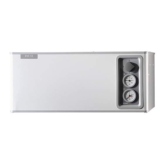
Page 6: Front Panel
Front panel Offset heating curve Heating curve selection Boiler temperature Switch Clock Night change OF F °C Boiler Fuse Indicator lamps pressure Selector EVC 13... - Page 7 “Selector”. Fuse Fuse (2.5 A) for control and the circulation pump. Selector Selector switch with three positions. Permanent day Night change not active Auto mode. Timer controlled night change. Permanent night Night change permanently active. EVC 13...
-
Page 8: Settings
Warm weather conditions If the room temperature is low, turn the Offset heat- ing curve knob one step clockwise. If the room temperature is high, turn the Offset heat- ing curve knob one step anticlockwise. EVC 13... -
Page 9: Changing The Room Temperature
The change is active during the pe- riods set on the clock (see section “Clock” - “Programming the timer”). NOTE! An increase in the room temperature may be inhibited by the radiator or floor heating thermostats, if so these must be turned up. EVC 13... -
Page 10: Offset Heating Curve -2
Heating curve VÄRMEKURVA °C The heating control system on EVC 13 is controlled by the outside temperature. This means that the boiler temperature and with that also the flow temperature is regulated in relation to the current outdoor tempera- ture. -
Page 11: Clock
“Night change” selector. The selector pressing the keys, positioned around the timer dis- switches between “Permanent day”, “Permanent play. The numbers around the display represent night” and “Auto mode.”. See the section “Front panel”. the 24 hours in a day. EVC 13... -
Page 12: Monitoring And Maintenance
Tariff control (extra option) so see the section “Commissioning and adjusting” - “Filling”. The external water heater is always fed via EVC 13 ir- respective of external control when the power switch is pressed in so that the red marking is visible. -
Page 13: Causes And Dealing With Malfunctions
Low room temperature No hot water Circuit or main MCB tripped. In those cases the EVC 13 feeds an electric hot water heater, no hot water may be due to one of the follow- Tripped control fuse, see the section “Monitoring ing reasons: and maintenance”... -
Page 14: Resetting The Temperature Limiter
030 65 040 90 Helping the circulation pump to start Shut down EVC 13 by turning the switch (8) to “0”. Loosen the venting screw with a screwdriver. Hold a cloth around the screwdriver blade as a certain Venting screw Luftningsskruv amount of water may run out. -
Page 15: Pipe Installation
R15 ( " ) hose coupling. The cap on the dry. EVC 13 is designed to be positioned on top of the valve should be dismantled and the hose coupling an electric water heater type NIBE COMPACT. Make... -
Page 16: Expansion Vessel
0.5 (bar). Pressure controlled bypass valve EVC 13 is equipped with a pressure controlled bypass valve (48). This is to protect the circulation pump in in- stallations where the radiator flow can completely stop. When the radiator side is closed, the boiler water circulates across the pump internally in EVC 13. -
Page 17: Electrical Installation
The boiler is connected on terminal (9) to 400 V 3- phase, neutral + earth via a distribution board with fuses. EVC 13 does not include an isolator switch on the NOTE! incoming electrical supply. The installation must be preceded by a circuit-breaker with at least a 3 mm Electrical installation and service breaking gap. -
Page 18: Returning Output/Self Test
NOTE! However, there is always 4 minutes between each step size (see the table under the heading “Output control immersion heater”). EVC 13 has an in- tegrated self-test program. This is activated by holding down the quick start button, and then pressing the restart button. -
Page 19: Max Thermostat/Temperature Limitation
The electrical connection is made on the 1.96 1.47 relay card's (29) terminal block (14). 1.60 1.27 1.31 1.09 Max. permitted cable length: 1.08 0.94 Cu-cable Ø 0.6 mm 20 m 0.746 0.70 Cu-cable 1.0 mm 80 m 0.525 0,51 EVC 13... -
Page 20: Commissioning And Adjusting
When the system has stabilised (correct pressure in the boiler and all air removed) the heating controls can be set at the required value. See the section “Settings” - “Heating control system” and “Front panel. EVC 13... -
Page 21: Electrical Circuit Diagram
Strömställarläge Position 0 Läge 0 Position 1 Läge 1 Position 2 Läge 2 Position n Läge R N L1 L2 L3 D A N NOTE! Terminal 26 is live even when the switch is in the 0 position. EVC 13... -
Page 22: Component Placement
595 2644 130 P/N: 25 - 60 PC:0 202 Type UPS 230- 50H z 2,5u F IP 44 TF 110 P1(W) 1/1(A) Clas s H 020 45 030 65 Max 10ba 040 90 12 34 14 29 51 80 EVC 13... -
Page 23: List Of Components
Filling connection .................. Ø 15 mm Drainage connection, boiler water ............R 15 male Pressure expansion vessel 12 litres, initial pressure 50 kPa (0.5 bar) Connection overflow pipe safety valve boiler water ....Clamping ring 22 mm 103 Serial number sign EVC 13... -
Page 24: Dimensions
Dimensions and setting-out coordinates Free space for air gap Fritt utrymme för luftspalt Floor Golv Skyddsklenspänning Protective low voltage Supply, electric boiler Matning, elpanna Tariff control, VVB Tariffstyrning, vvb * Free space for inspection and service. Measuring principle Compression ring Klämring EVC 13... -
Page 25: Accessories
Fuse and tariff kits for the power supply of an external electrical hot water heater Components in the fuse and tariff kits are fitted in EVC 13 in the pre- pared places. Electrical connection is done according to the electrical circuit diagram below. -
Page 26: Technical Specifications
Fuse pressure 2.5 bar (0.25 MPa) Max thermostat setting 30 – 85 °C Expansion vessel volume 12 litres Part no. 089 300 Enclosed kits Outside sensor Current sensors 3 x Part no. 018 764 Part no. 018 569 EVC 13... - Page 28 Fax: 22 90 66 09 Jerikoveien 20 E-mail: info@nibe.se 1067 Oslo www.nibe-villavarme.no Tel: 085 662 84 90 NIBE-BIAWAR Sp. z o. o. Fax: 085 662 84 14 Aleja Jana Pawła II 57 E-mail: sekretariat@biawar.com.pl 15-703 BIAŁYSTOK www.biawar.com.pl Tel: +46 - (0)433 - 73 000...
Need help?
Do you have a question about the EVC 13 and is the answer not in the manual?
Questions and answers