Advertisement
Quick Links
FAILURE TO READ AND FOLLOW ALL INSTRUCTIONS CAREFULLY
BEFORE INSTALLING OR OPERATING THIS CONTROL COULD CAUSE
PERSONAL INJURY AND/OR PROPERTY DAMAGE.
NPT Tank Connection
4 Pin Din Electrical Connection
ELECTRICAL CONNECTIONS
JB - Junction Box
FL - 6" Free Leads (Stripped
for Conduit Fitting)
DN - 4 Pin Din Plug
CB - 6' Cable (in non-shielded Jacket)
SG - Sight Glass Only
TANK CONNECTIONS
P - ½" NPT
R - 1¼" - 12 Rotolock
S - ¾" - 16 UNF-2A
(Included O-Ring)
NOTE
Inspect glass in Switch body, if product looks cracked,
damaged or dropped, please do not use.
TANK CONNECTIONS
Glass nut is always to be installed into compressor on true
horizontal within +10°.
FOR ½" NPT (Option P) & ¾"-16 UNF (Option S):
1. Place thread sealant on Teflon tape on threads.
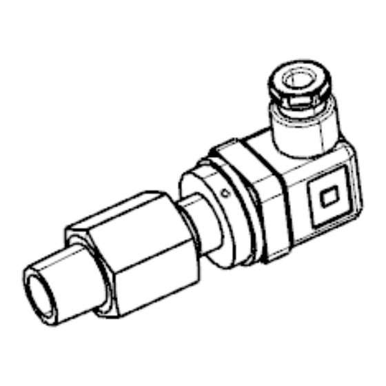
Rotolock Tank Connection
Free Lead Electrical Connection
OLS XXX - XXXNX
NOTE: OLSX (low-temp) versions function the same as OLS versions
emerson.com/white-rodgers
OLS Optical Level Switch
INSTALLATION INSTRUCTIONS
Junction Box Electrical Connection
2. (Option S only) Ensure o-ring
shape with no cuts.
3. Tighten 1½" to 3 turns past finger tight such that 3-6
threads are engaged.
For 1¼"-12 ROTOLOCK (Option R):
1. Hand tighten 2-3 turns.
2. Use double wrench (one to hold tank connection and one
to turn nut) to fully tighten onto tank.
INSTALLATION
Straight Thread (3/4"-16)
Tank Connection
SWITCH TYPE
NC - Normally Closed
NO - Normally Open
INPUT VOLTAGE
024 - 24 VAC
120 - 120 VAC
240 - 208/240 VAC
INSTALLATION
is in good
PART NO. 2000-1072/04
2023
Advertisement

Related Manuals for Emerson OLS


Summary of Contents for Emerson OLS
- Page 1 120 - 120 VAC 240 - 208/240 VAC R - 1¼" - 12 Rotolock S - ¾" - 16 UNF-2A NOTE: OLSX (low-temp) versions function the same as OLS versions (Included O-Ring) INSTALLATION NOTE Inspect glass in Switch body, if product looks cracked, 2.
- Page 2 INSTALLATION ELECTRICAL CONNECTIONS Connect leads to electrical controls of tank/compressor as per below schematics. N.C. TYPE = WHITE N.O. TYPE = WHITE WITH BLACK STRIPE SUPPLY VOLTAGE L1 - BLACK LOAD SWITCH 24V = ORANGE 120V = YELLOW 240V = RED EXTERNAL LOAD OR PULL UP EXTERNAL LOAD OR PULL UP N.O.
- Page 3 INSTALLATION FOR OLS SGP MODELS: INSTALL SWITCH MODULE INTO SWITCH BODY INSTALL SWITCH BODY ONTO COMPRESSOR 1. Ensure cap plug is still on Level Switch Module (Figure 2). NOTE If part is dropped or hits the floor, the part should not be used.
- Page 4 OLS Optical Level Switch (09/20) Emerson and White-Rodgers are trademarks of Emerson Electric Co. ©2020 Emerson emerson.com/white-rodgers Electric Co. All rights reserved.
Need help?
Do you have a question about the OLS and is the answer not in the manual?
Questions and answers