
Related Manuals for Lamborghini Caloreclima LMB LO 700


Summary of Contents for Lamborghini Caloreclima LMB LO 700
- Page 1 UNI EN ISO 9001 CERTIFIED COMPANY Three-stage diesel burner LMB LO 700 (3ST) LMB LO 1000 (3ST) LMB LO 1300 (3ST) LMB LO 2000 (3ST) Installation, use and maintenance manual...
-
Page 2: Table Of Contents
Thank you for your preference towards our products. LAMBORGHINI CALORECLIMA is a Company that has daily involvement in the research for innovative technical solutions, able to satisfy all needs. The constant presence of out products on the Italian and international market is guaranteed by a capillary network of Agents and Authorised dealers. -
Page 3: General Standards
GENERAL STANDARDS This manual is an integral and essential part of the product and must be given to the installer. Read the warnings given in this manual as they supply important indications regarding installation, use and main- tenance safety. Keep this manual carefully for future reference. The burner must be installed in compliance with the Standards in force, according to the manufacturer’s instructions and by qualified staff Incorrect installation can cause injury/ damage to persons, animals or objects, for which the manufacturer cannot be held responsible. - Page 4 The burner room must always be kept clean and free from volatile substances, which could be sucked inside the fan and block the interior pipes of the burner and the combustion head. Dust is extremely dangerous, especially if this can deposit on the fan blades, where it will reduce ventilation and produce pollution during combustion. The dust an also accumulate on the rear part of the flame stability disc in the combustion head and cause a poor air/ fuel mixture.
-
Page 5: Technical Data
TECHNICAL DATA LO 700 LO 1000 LO 1300 LO 2000 Model Type Three stages Functioning Intermittent Maximum heat output 1370 1976 Minimum heat output lass Maximum flow rate kg/h 59,4 Minimum flow rate kg/h 11,4 16,1 41,1 59,8 Electric protection rating Motor electric power supply (three phase) V / Hz 400 / 50... -
Page 6: Work Curves
WORK CURVE LO 700 3ST 7,00 6,00 5,00 4,00 3,00 2,00 1,00 0,00 LO 1000 3ST 8,00 7,00 6,00 5,00 4,00 3,00 2,00 1,00 0,00 1000 kW... - Page 7 LO 1300 3ST 14,00 12,00 10,00 8,00 6,00 4,00 2,00 0,00 1000 1100 1200 1300 1400 LO 2000 3ST 14,00 12,00 10,00 8,00 6,00 4,00 2,00 0,00 1000 1200 1400 1600 1800 2000...
-
Page 8: Dimensions
DIMENSIONS Crew LO 700 LO 1000 LO 1300 LO 2000... -
Page 9: Main Components
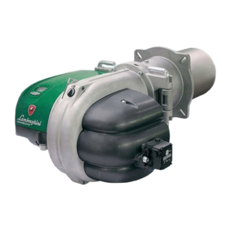
MAIN COMPONENTS 17 Flange insulation 5 Air vent lid 11 Air servo-motor 18 Air vent 6 Diesel pump 12 Control unit 19 Photoresistence 1 Motor 7 Flow nozzle 13 Contactor-motor relay 2 Control panel P Hinge pins 8 Burner flange 14 Solenoid valves 3 Display 9 Ring regulation... -
Page 10: Boiler Assembly
• The place of installation must be without dusts, objects or inflammable materials or corrosive gases. RECOMMENDATIONS FOR USE To prevent injury/damage to persons and the environment in which the appliance is used, the following notes must be complied with! •... -
Page 11: Electric Connections
ELECTRIC CONNECTIONS READ THE GENERAL STANDARDS ON PAGE 3 CAREFULLY - NEUTRAL TO EARTH: in the case of power supply mains with NEUTRAL CONNECTED TO EARTH connect the mains power supply NEUTRAL to the appliance NEUTRAL. - INSULATED NEUTRAL: in the case of mains power supply with INSULATED NEUTRAL it is necessary to use an insulation transformer.Connect a terminal of the insulation transformer secondary to the appliance EARTH and NEUTRAL.Now connect the other terminal of the transformer secondary to the appliance LINE. - Page 12 V E 1 V E 2 V E 3 L Line N Neutral L1 Three phase line L2 Three phase line L3 Three phase line M Burner motor T m f 1 T m f L 1 L 2 L 3 SL Circuit breaker switch FR Photoresistence TR Ignition transformer...
-
Page 13: Appliance
APPLIANCE Main features - EMC filter on the board; - Protection fuse on the board; - Stable timers not affected by the voltage and/or temperature changes (system management by microprocessor); - protection in case of low voltage power supply; - protection in case of high power supply voltage; - non-volatile block;- intermittent functioning: regulation and self-diagnosis stop every 24h;... - Page 14 The power supply voltage must be at least 180Vac in order to allow a starting cycle to be performed. If the network voltage falls below 156Vac, the appliance stops and signals the anomaly. The starting cycle can only be carried out again if the power supply voltage exceeds 180Vac. Protection in case of high power supply voltage The power supply voltage must be at below 275Vac in order to allow a starting cycle to be performed.If the network voltage exceeds 280Vac, the appliance stops and signals the anomaly.
- Page 15 FUNCTIONING CYCLE Ignition On closure of the heat request contact, the fan motor and ignition transformer are inserted and total opening of the air damper is commanded. On reaching total opening the pre-ventilation (and pre-ignition) time starts during which the flame amplifier test is performed along with components associated to safety functions.
-
Page 16: Interface
USER INTERFACE The control and command panel can be used to monitor the status of the burner, access the diagnostic and confi- guration menus of the system and release the appliance. The control and command panel is composed of an LCD with back-lit display area and 4 function keys. - Page 17 Display The control and command panel makes 3 display methods available: NORMAL: in this mode, icons appear on the display that are relative to the burner functioning state. If there are no anomalies present, the display shows the number of ignition cycles performed by the burner and the total number of functioning hours.
- Page 18 However, if anomalies are present, the anomaly code (see table 1) and the type of anomaly (volatile or non- volatile) will be displayed at the same time. NON VOLATILE VOLATILE Anomaly Anomaly code code Flashing code and anomaly Flashing back-light icon ANOMALY CODE MEANING...
- Page 19 If special functions are activated, the function in progress is displayed. Manual functioning mode: Flashing Pump engagement: Temporary shutdown:...
-
Page 20: Access To The Menus
ACCESS TO THE MENUS MENU ACCESS ENABLING PROCEDURE In order to enable the display and consequent management of the menus stated previously, during the normal display phase it is necessary to follow the procedure given: a) PROLONGED PRESSING OF KEY “ ”... - Page 21 INFO MENU If the burner is two-stage or three-stage, the INFO MENU is organised as per table. MENU REPRESENTATION INFORMATIO 1st stage burner functioning hours 2nd stage burner functioning hours 3rd stage burner total functioning hours(three-stage only) TIMER Burner total functioning hours Timer reset Burner functioning cycles (1st stage) 2nd stage burner functioning cycles...
- Page 22 Timer The function hours of the burner are displayed respectively in first and second stage (if two-stage burner). Stage burner The total functioning hours of the burner are also displayed. To reset all counters relative to the hours of functioning of the burner, press the key i during the following di- splay: By doing this, access the reset consent confirmation display with duration of 5s.
- Page 23 Cycles-counter The burner functioning cycles are displayed respectively in first and second stage (total functioning cycles of the burner are equal to the first stage cycles). (In the case of modulating burner, only the total functioning cycles of the burner are displayed). Stage burner Functioning cycles in second stage...
- Page 24 Fuel consumption Using the INSTALLER MENU it is possible to set the hourly fuel consumption respectively of the first and second stages.(Unit of measurement: Kg/h). When this has been performed, it is possible to determine the total fuel consumption relative to the individual functioning stages of the burner.
- Page 25 Flame signal The flame signal value is displayed in uA. Flame signal in micro A If the flame signal read should exceed the flame signal detection threshold value by 10 times, the display is: Flashing Air damper servo-motor The current position of the air damper servo-motor is displayed (closure total, first stage, total opening or second stage).
- Page 26 The total opening cycles performed by the servo-motor are also displayed. To reset the servo-motor opening cycles-counter, press the key i during the following display: flashing By doing this, access the reset request confirmation display with duration of 5s. Pressing the key again determines the reset of the servo-motor cycle meter and the return to the servo-motor opening cycles display.
- Page 27 NOMALIES LOG MENU The HIST MENU is organised as per table 3. MENU REPRESENTATION INFORMATION Anomalies log per functioning hours (Posizione 1/8) Anomalies log per functioning hours (Posizione 2/8) Anomalies log per functioning hours (Posizione 3/8) Anomalies log per functioning hours (Posizione 4/8) ANOMALIES LOG (DISPLAY BY HOURS) Anomalies log per functioning hours (Posizione 5/8)
- Page 28 An example is given below. (In position 1 no ignition block occurring after 99 burner functioning hours). ANOMALIES LOG (DISPLAY BY CYCLES) It is possible to display a log relative to the last anomalies occurring. The log keeps trace of the last 8 anomalies (anomaly code and type) and of the respective burner functioning cycles.
- Page 29 By doing this, access the reset request confirmation display with duration of 5s. flashing Pressing the key again determines the reset of the anomalies log and the return to the position 1 log display for functioning hours. PARAM MENU (PARAMETERS) The PARM MENU is organised as per table MENU REPRESENTATION...
- Page 30 POST-VENTILATION TIME It is possible to set the post-ventilation time from a minimum of 0s (post-ventilation disabled) to a maximum of 255s. Post-ventilation time (in sec) Press key i to access the PARAMETER VALUE MODIFICATION mode, during which the value of the parameter displayed flashes.
- Page 31 TThis delay can be set from 0 to 30% of the second stage air flow rate with respect to the first.Advance = 0: second stage solenoid valve ope- ning in pre-defined position (second stage cam).Advance=30: second stage solenoid valve opening in advance with respect to the pre-defined position (maximum value settable).
-
Page 32: Regulations
REGULATIONS It is necessary to position the air ring (Diagram A) in the desired working point referring to diagram A. Based on the working point of the burner (supplied power / pressure in combustion chamber) a position is indicated (min - 1 - 2 - 3 - max) for the air adjustment ring which corresponds with the marks on rod T (Fig. - Page 33 Combustion head shutter regulation LO 1300 Ex. If the burner should operate at 1100kW with a counterpressure of 4 mbar, the air ring must be positioned in correspondence with mark 3 on rod T (Fig. 4) Diagram A 14,00 12,00 10,00 8,00 6,00...
- Page 34 Combustion head shutter placement To adjust air shutter position, unscrew knob P and move the shutter in correspondence with the desired value, reading plate T. Tighten the knob after adjustment has been completed. Fig. 4 Detail of shutter adjustment Positions corresponding to the curves in diagram A (plate T).
- Page 35 Electrodes positioning Two electrodes are envisioned for ignition and one for flame control: these must not touch the deflector or other metal parts for any reason as they would loose their function, compromising burner functioning. It is good practice to check the correct position after every intervention on the head. 18,5 LO 700 LO 1000...
- Page 36 Air servo-motor regulation The air damper is activated by an electric servo-control. The positions of the damper are determined via the cams, with reference to the scale on the relevant disc. The cams are manoeuvred by means of the supplied spanner: they are clutched and self-locked. The air damper servo-motor must be of the type indicated below.
- Page 37 Flame detection - Flame detection takes place via photoresistance with the following features: Lighting levels: Volt DCFlame detection threshold: >3.5 <1,5 Flame switch-off threshold: <2.5 >1,8 Parasite flame threshold: >1.5 <2,3 Maximum length of flame detection cable: 1.5 m Repetition of the cycle in case the flame switches off in normal working position: If the flame goes out in normal working position, the appliance repeats the start-up cycle (max 3 cycle repetitions);...
- Page 38 Hydraulic circuit...
- Page 39 Nozzles selection Inside every PUMP/NOZZLE PRESSURE box there are two values. The flow rate in kg/h is expressed at the top, in kW at the bottom. 1,36 1,44 1,52 1,59 1,67 1,73 1,80 1,86 1,92 1,98 2,04 2,10 2,15 2,20 0,40 16,1 17,1...
- Page 40 18,70 19,83 20,90 21,92 22,90 23,83 24,73 25,60 26,44 27,25 28,04 28,81 29,56 30,29 5,50 221,8 235,2 247,9 260,0 271,6 282,6 293,3 303,6 313,6 323,2 332,6 341,7 350,6 359,3 20,40 21,63 22,80 23,92 24,98 26,00 26,98 27,93 28,84 29,73 30,59 31,43 32,25 33,04...
-
Page 41: Maintenance
Dual-pipe supply N. B.: If the piping length exceeds 60m, a supply pump is recommended - d10 (2), d12 (2): for two flame burners.. Combustion control In order to obtain the best combustion yield, and with respect for the environment, it is recommended to perform- control and regulation of combustion with suitable tools. - Page 42 It is now possible to access the screws (2) that block the electric control board lid (B). Loosen the screws (2) and lift the lid (B) paying attention to the lid blocking hooks positioned on the rear of the electric control board Ganci Hooks Air vent - air flap maintenance...
- Page 43 Burner opening and access to the combustion head and regulation of the air ring To access the combustion head and to regulate the air ring, loosen the two screws (4). Slide out the right (RH) or left (LH) pin according to necessity and the position of the valves unit (RH pin in the example). At this point it is possible open the burner by turning the pin remaining in the seat.
- Page 44 The illustrations and data given are indicative and not binding. Lamborghini Caloreclima reserves the right to make all modifications it deems appropriate for improvement of the pro- duct without forewarning. The unit and its accessories must be appropriately disposed of in com- pliance with current regulations.
Need help?
Do you have a question about the LMB LO 700 and is the answer not in the manual?
Questions and answers