
Related Manuals for Lamborghini Caloreclima LMB G 1300


Summary of Contents for Lamborghini Caloreclima LMB G 1300
- Page 1 UNI EN ISO 9001 CERTIFIED COMPANY Two-stage progressive/modulating mode gas burner LMB G 1300 LMB G 2000 Installation, use and maintenance manual...
-
Page 2: Table Of Contents
Congratulations on your excellent choice Thank you for your preference towards our products.LAMBORGHINI CALORECLIMA is a Company that has daily involvement in the research for innovative technical solutions, able to satisfy all needs. The constant presence of out products on the Italian and international market is guaranteed by a capillary network of Agents and Authorised dealers. -
Page 3: General Standards
GENERAL STANDARDS This manual is an integral and essential part of the product and must be given to the installer. Read the warnings given in this manual as they supply important indications regarding installation, use and maintenance safety. Keep this manual carefully for future reference. The burner must be installed in compliance with the Standards in force, according to the manufacturer’s instructions and by qualified staff Incorrect installation can cause injury/ damage to persons, animals or objects, for which the manufacturer cannot be held responsible. - Page 4 any air duct or ventilation grid and external dissipation, with the purpose of preventing: - the formation of toxic/ explosive gas mixtures in the air of the burner room; - combustion with insufficient air, from which dangerous, costly and polluting functioning occurs. The burner must always be protected from rain, snow and freezing.
-
Page 5: Description
The length of the cables used must allow the burner and any boiler door to be opened.The electric connections must be made exclusively by qualified staff and the regulations in force on the subject of electricity must be re- spected. After all packaging material has been removed, control the contents and ensure that these have not been damaged in any way during transport.If in doubt, do not use the burner and contact the supplier. -
Page 6: Technical Data
TECHNICAL DATA G 1300 G 2000 Model Type Two-stage progressive or modulating Functioning Intermittent Regulation Air/gas proportional valve Maximum heat output 1296 1918 Minimum heat output class Gas category G20 / G30-G31 Maximum gas flow rate (15°C - 1013.5 mbar)-natural gas 136,5 Minimum gas flow rate (15°C - 1013.5 mbar)-natural gas 36,5... - Page 7 Work curves The work range was obtained at an ambient temperature of 15°0, at an atmospheric pressure of 1013.5 mbar (at 0 metres above sea-level) and with the adjustments recommended in this instruction. G 1300 14,00 12,00 10,00 8,00 Optimal operating range 6,00 4,00 2,00...
-
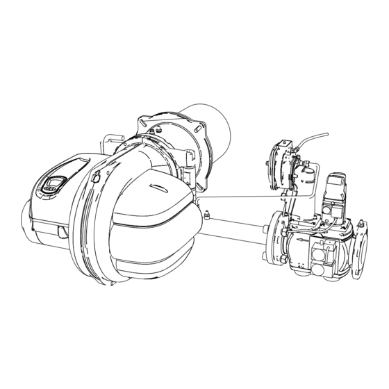
Page 8: Main Components
MAIN COMPONENTS... -
Page 9: Dimensions
DIMENSIONS G 1300 G 2000 VCV-L240 VCV-L350 VGD20 G 1300 1070 1”1/2 2” 2” VGD 20.403 VGD 20.503 VGD 40.065 G 2000 1070 1070 1050 2” 2”... -
Page 10: Valves Unit Description
VALVES UNIT VCV L (slow opening) VCV L valve body chamber combustion signal (possible) Minimum gas pressu- re pressure switch Air signal withdrawal pipe (polyethylene) Valve proving system pressure switch (1) Note: installation of the combustion chamber compensation tube is recommended in order to optimise opera- tion of the valve. - Page 11 VGD 20. chamber combustion signal SKP 75 (possible) Air signal withdrawal pipe (polyethylene) SKP 15 Gas signal withdrawal pipe (rigid) VGD 20 valve body Minimum gas pressu- re pressure switch Valve proving system pressure switch VGD 40. chamber combustion signal (possible) SKP 75 Air signal withdrawal...
-
Page 12: Pressure/Flow Rate Curves
PRESSURE/FLOW RATE CURVES G 1300 They indicate the gas pressure in mbar, (in the various points of the gas ramp) necessary to obtain a determined flow rate in m3/h. The pressures are measured with the burner functioning and are intended with combustion chamber at 0 mbar. - Page 13 PRESSURE/FLOW RATE CURVES G 2000 They indicate the gas pressure in mbar, (in the various points of the gas ramp) necessary to obtain a determined flow rate in m3/h. The pressures are measured with the burner functioning and are intended with combustion chamber at 0 mbar.
-
Page 14: Receiving The Product
RECEIVING THE PRODUCT The burner is supplied protected by cardboard or cardboard/wood packaging. WARNING The instruction manuals are an integral part of the appliance and therefore must be read before installing and starting the burner and must be kept with care. The documents envelope, positioned inside the packaging, contains the following material: - Installation and maintenance book - Warranty certificate... -
Page 15: Boiler Assembly
BOILER ASSEMBLY The burner is fixed by the flange, placing the supplied insulated gasket between the plate and the boiler. For drilling of the boiler and positioning of the fastening screws, refer to the diagram. G 1300 G 2000 L = Useful entrance lenght flow nozzle Insulating gasket GAS CONNECTION The system must be complete with the accessories prescribed by the Standards: do not exert mechanical stress... -
Page 16: Valves Unit Assembly
VALVES UNIT ASSEMBLY VCV L (slow opening) To fix the valves unit (fig. A) to the burner, use the 4 washers (a) and the 4 M12 x 20 screws supplied with the valves unit, paying attention that the cork/rubber gasket (c) is positioned correctly and there are no gas leaks in the coupling. - Page 17 VGD 20..To fix the valves unit (fig. A) to the burner, use the 4 washers (a) and the 4 M12 x 20 screws supplied with the valves unit, paying attention that the cork/rubber gasket (c) is positioned correctly and there are no gas leaks in the coupling.
- Page 18 VGD 40..To fix the valves unit (fig. A) to the burner, use the 4 washers (a) and the 4 M12 x 20 screws supplied with the valves unit, paying attention that the cork/rubber gasket (c) is positioned correctly and there are no gas leaks in the coupling.
-
Page 19: Electric Connections
ELECTRIC CONNECTIONS READ THE GENERAL STANDARDS ON PAGE 3 CAREFULLY - NEUTRAL TO EARTH: in the case of power supply mains with NEUTRAL CONNECTED TO EARTH connect the mains power supply NEUTRAL to the appliance NEUTRAL. - INSULATED NEUTRAL: in the case of mains power supply with INSULATED NEUTRAL it is necessary to use an insulation transformer. - Page 20 Nero Grigio L=200 2 G/V 4 G/V 1 G/V Blu L=200 Bianco L=200 Viola L=200 Arancio L=200 Grigio L=200 Marrone L=200 Blu L=200 Grigio L=200 Arancio L=100 Bianco L=100 3 G/V 3 G/V Blu L=100 PG Gas pressure switch L Line PA Air pressure switch L1 L2 L3 N Neutral...
-
Page 21: Appliance
APPLIANCE Main features - EMC filter on the board. Protection fuse on the board. - Stable timers not affected by the voltage and/or temperature changes (system management by microproces- sor). - Protection in case of low/high voltage power supply. - Monitoring of air pressure switch functioning. Non-volatile block. remote reset; - Intermittent functioning: regulation and self-diagnosis stop every 24h. - Page 22 Protection in case of high power supply voltage The power supply voltage must be at below 275Vac in order to allow a starting cycle to be performed.If the net- work voltage exceeds 280Vac, the appliance stops and signals the anomaly.The starting cycle can only be carried out again if the power supply voltage falls below 275Vac.
-
Page 23: Functioning Cycle
FUNCTIONING CYCLE Burner control Ignition On closure of the heat request contact and when the correct status of the air pressure contact has been verified, the fan motor is inserted and the air damper total opening is controlled.On reaching total opening of the damper and switch-over of the air pressure switch contact has been verified, the pre-ventilation time starts during which the flame amplifier test is performed along with components associated to safety functions. - Page 24 corresponding to start-up flow rate (with gas flow always closed). c) Formation sequence of the start-up flame: the coils relative to the gas solenoid valves are excited and the gas regulator is partially open in relation to the start-up air pressure. d) Passage sequence to the main flame or second stage: the servo-control activates the opening of the air (up to maximum flow rate calibration) whose increase in pressure causes the gradual increase of the gas flow rate.
- Page 25 Two-stage progressive functioning diagram With Tmf thermostat with high/low flame...
- Page 26 Diagram of functioning with continuous modulation...
-
Page 27: User Interface
USER INTERFACE The control and command panel can be used to monitor the status of the burner, access the diagnostic and confi- guration menus of the system and release the appliance. The control and command panel is composed of an LCD with back-lit display area and 4 function keys Icon meaning ICON... - Page 28 Display The control and command panel makes 3 display methods available: NORMAL: in this mode, icons appear on the display that are relative to the burner functioning state.If there are no ano- malies present, the display shows the number of ignition cycles performed by the burner and the total number of functioning hours.If an anomaly occurs, the display shows the relative code and signals the type of anomaly, (volatile or non-volatile).
- Page 29 However, if anomalies are present, the anomaly code (see table 1) and the type of anomaly (volatile or non- volatile) will be displayed at the same time. NON VOLATILE VOLATILE Anomaly Anomaly code code Flashing code and anomaly Flashing back-light icon CODICE ANOMALIA SIGNIFICATO...
-
Page 30: Access To The Menus
If special functions are activated, the function in progress is displayed. Manual functioning mode: Flashing Temporary shutdown: ACCESS TO THE MENUS MENU ACCESS ENABLING PROCEDURE In order to enable the display and consequent management of the menus stated previously, during the normal display phase it is necessary to follow the procedure given: a) PROLONGED PRESSING OF KEY “... - Page 31 c) PRESSING KEY “ ” . During phase b) (maximum duration 10s) pressing key “ ” once enables the display and management of the INFO, HIST, PARAM and SERV menus. The menu management enabling is confirmed by the following display: The enabling on display and management of the menus has duration of 120s, after which the return to normal display mode takes place.
- Page 32 Modulating burner MENU REPRESENTATION INFORMATION TIMER Burner total functioning hours Timer reset Burner functioning cycles CYCLES-COUNTER Burner no ignition cycles Cycle-counter reset MENU INFO FUEL CONSUMPTION Flame signal intensity Air damper servo-motor current position FLAME SIGNALS Air damper servo-motor total opening cycles AIR DAMPER SERVO-MOTOR Servo-motor cycles reset Electrical frequency...
- Page 33 By doing this, access the reset consent confirmation display with duration of 5s. flashing Pressing the key again during this display determines the reset of all meters relative to the functioning hours and the return to first stage functioning hours display. Cycles-counter The burner functioning cycles are displayed respectively in first and second stage (total functioning cycles of the burner are equal to the first stage cycles).(In the case of modulating burner, only the total functioning cycles of the...
- Page 34 Flame signal The flame signal value is displayed in uA. Flame signal in micro A If the flame signal read should exceed the flame signal detection threshold value by 10 times, the display is: Flame signal in micro A Air damper servo-motor The current position of the air damper servo-motor is displayed (closure total, first stage, total opening or second stage).
- Page 35 The total opening cycles performed by the servo-motor are also displayed. To reset the servo-motor opening cycles-counter, press the key i during the following display: flashing By doing this, access the reset request confirmation display with duration of 5s. Pressing the key again determines the reset of the servo-motor cycle meter and the return to the servo-motor opening cycles display.
- Page 36 NOMALIES LOG MENu The HIST MENU is organised as per table 3. MENU RAPPRESENTAZIONE INFORMAZIONI Anomalies log per functioning hours (Position 1/8) Anomalies log per functioning hours (Position 2/8) Anomalies log per functioning hours (Position 3/8) Anomalies log per functioning hours (Position 4/8) ANOMALIES LOG (DISPLAY BY HOURS) Anomalies log per functioning hours (Position 5/8)
- Page 37 An example is given below. (In position 1 no ignition block occurring after 99 burner functioning hours). ANOMALIES LOG (DISPLAY BY CYCLES) It is possible to display a log relative to the last anomalies occurring. The log keeps trace of the last 8 anomalies (anomaly code and type) and of the respective burner functioning cycles.
- Page 38 By doing this, access the reset request confirmation display with duration of 5s. flashing Pressing the key again determines the reset of the anomalies log and the returnto the position 1 log display for functioning hours. ARAMETERS MENu The PARM MENU is organised as per table 4. MENU RAPPRESENTATION SETTABLE VALuES...
- Page 39 Press key i to access the PARAMETER VALUE MODIFICATION mode, during which the value of the parameter displayed flashes. In MODIFY PARAMETER VALUE mode, use the + and – keys to modify the value.Press key i to memorise the current value displayed.To exit this mode without memorising the value, press key R or wait 10s without pressing the keys.
- Page 40 displayed flashes. In MODIFY PARAMETER VALUE mode, use the + and – keys to modify the value. Press key i to memorise the current value displayed.To exit this mode without memorising the value, press key R or wait 10s without pressing the keys. SECOND STAGE SOLENOID VALVE ADVANCED ACTIVATION (Not managed if MODULATING BURNER) It is possible to introduce an advance on the second stage solenoid valve activation.
-
Page 41: Regulations
ADJUSTEMENT Check some adjustments before switching on the burner. The air actuator has been factory pre-calibrated. The high flame cam must be adjusted between 80 and 90° and the low flame cam to about 30°. Air servo-motor regulation (G 1300 - G 2000) The air damper is activated by an electric servo-control. - Page 42 If the burner is to operate inside the operating range where a gas diaphragm is present, you must install it. Gas reduction diaphragm - (G 1300) When the maximum power of the burner is selected inside the shaded area (see Fig. 1), to increase the gas pres- sure signal in order to maintain the gas signal and air signal ratio within the operational limits of the valve, insert the gas reduction diaphragm (DG) provided with the burner.
- Page 43 Gas reduction diaphragm (only natural gas) - (G 2000) When the maximum power of the burner is selected inside the shaded area (see Fig. 4), to increase the gas pres- sure signal in order to maintain the gas signal and air signal ratio within the operational limits of the valve, insert the gas reduction diaphragm (DG) provided with the burner.
- Page 44 Adjust the air shutter in the position shown in the diagram, based on foreseen flow control valve operation on the burner. Gas reduction combustion head regulation - (G 1300) It is necessary to position the air ring (Fig. 5) in the desired working point referring to diagram A. Based on the working point of the burner (supplied power / pressure in combustion chamber) a position is indicated (min - 1 - 2 - 3 - max) for the air adjustment ring which corresponds with the marks on rod T (Fig.
- Page 45 Gas reduction combustion head regulation - (G 2000) It is necessary to position the air ring (Fig. 5) in the desired working point referring to diagram A. Based on the working point of the burner (supplied power / pressure in combustion chamber) a position is indicated (min - 1 - 2 - 3 - max) for the air adjustment ring which corresponds with the marks on rod T (Fig.
- Page 46 Combustion head shutter placement (G1300 – G2000) To adjust air shutter position, unscrew knob P and move the shutter in correspondence with the desired value, reading plate T. Tighten the knob after adjustment has been completed. Fig. 7 Detail of shutter adjustment Positions corresponding to the curves in diagram A (plate T)..
- Page 47 Right air flap blocking (G 1300) Securing point F screw Right damper pin Left damper pin Connection rod A Pin B When necessary, to block the right damper proceed as follows. extract the securing pin seeger ring from its housing (B) and remove the pin. bring the connection rod (A) to the securing point (F) on the semi-Archimedean screw.
- Page 48 Connect the instrument for combustion analysis, the pressure gauge for gas pressure to the combustion head and the low/high flame switch. Connect the gas pressure gauge to the inlet PV in order to measure gas pressure downstream from the ramp (see pressure/flow curves).
- Page 49 Start-up and valve adjustment procedure Low flame VCV gas valve start-up N = low flame adjustment V = high flame adjustment Start up the burner. If the burner does not start up, turn the N slightly in + position and repeat start-up. The burner starts..
- Page 50 Combustion adjustment, burner flow, high and low flame gas valve Combustion adjustment, burner flow, high and low flame gas valve (VCV and SKP). - Using the Tmf switch, bring the air actuator to the middle position between minimum and maximum (approximately at 45°...
- Page 51 Further adjustments (VCV L valve) Initial gas quantity adjustment (slow start-up) If burner start-up is too fast, you can intervene with slow start-up adjustment. Unscrew screw H and turn knob M (fig. 2-3). Lock screw H. Adjusting the opening brake Further optimisation of slow start-up can be ob- tained by regulating the opening brake, turning adjustment screw...
- Page 52 Gas diaphragm (natural gas only) Diaframma gas (solo gas naturale) For proper burner operation in the event of particular boiler-burner-chimney couplings, or with low back pressure in the combustion chamber, you may want to install the gas diaphragm anyway inside the entire burner operating Nel caso di particolari accoppiamenti caldaia-bruciatore-camino, o nel caso di contropressioni basse in camera range.
- Page 53 Gas and air pressure switch adjustment Minimum gas pressure pressure switch The gas minimum pressure pressure switch prevents burner start-up of stops it if it is functioning. If the gas pres- sure is not the minimum envisioned, it must be calibrated at 40% lower than the value of the gas pressure, which functions with maximum flow rate.
- Page 54 Air pressure switch regulation The air pressure switch has the task of putting the burner into safety or block conditions if the combustion air pres- sure is missing. This will be calibrated lower than the air pressure value at the burner when this is at nominal flow rate with 1st flame functioning, verifying that the value of CO does not exceed the value of 10.000 p.p.m.
- Page 55 Electrodes positioning (G 1300 - G 2000) Two electrodes are envisioned for ignition and one for flame control: these must not touch the deflector or other metal parts for any reason as they would loose their function, compromising burner functioning. It is good practice to check the correct position after every intervention on the head.
-
Page 56: Functioning Controls
FUNCTIONING CONTROLS Combustion control In order to obtain the best combustion yield and with respect to the environment, it is recommended to use suitable instruments to control and regulate combustion. Fundamental values to consider are: ● CO . It indicates with which air excess combustion takes place; if the air increases, the % value of CO decre- ases, and if the combustion air decreases the CO increases. - Page 57 c) Carry out a functioning cycle and, when burner ignition has been checked, close the gas supply in order to obtain flame switch-off:check the repetition of a cycle and consequent block shutdown caused by no ignition at the end of the safety time! d) Carry out a functioning cycle and, when burner ignition has been verified, open the contact relative to the air pressure switch:verify the immediate switch off of the solenoid valve and consequent block shutdown caused by air pressure switch anomaly after 10s!
- Page 58 The flame amplified circuit is sensitive to the variations of the continuous component (DC) of the flame signal current. TEST CIRCUIT Maximum length of flame detection cable: 1mAny short circuit between the detection electrode and earth does not allow the flame signal to be read. The appliance will perform a lock shutdown at the end of the safety time. Repetition of the cycle in case the flame switches off in normal working position: If the flame goes out in normal working position, the appliance repeats the start-up cycle (max 3 cycle repetitions);...
-
Page 59: Maintenance
MAINTENANCE Electric control board To access the electric control board, loosen the screws (1) that hold the terminal board cover (A). Remove the clamp covers (A). ATTENTION: these parts may be live during functioning. It is now possible to access the screws (2) that block the electric control board lid (B). Loosen the screws (2) and lift the lid (B) paying attention to the lid blocking hooks positioned don the rear of the electric control board. - Page 60 Air vent - air flap maintenance To access the air flap and the air closure system, loosen the screw (3) that blocks the air vent lid (C). ATTENTION: these parts may be moving during functioning...
- Page 61 Burner opening and access to the combustion head and regulation of the air ring To access the combustion head and to regulate the air ring, loosen the two screws (4). Slide out the right (RH) or left (LH) pin according to necessity and the position of the valves unit (RH pin in the example). At this point it is possible open the burner by turning the pin remaining in the seat.
-
Page 62: Gas Conversion
Combustion head extraction Gas seal gasket ATTENTION. During the assembly phase of the combustion head in its seat, control that the gas sealing gasket, highlighted in the figure, is well positioned GAS CONVERSION To transform from the operation of a gas burner to another, replace the burner head with special “KIT COMBU- STION HEAD”. -
Page 63: Functioning Irregularity
Functioning irregolarity DEFECT CAUSE REMEDY Control the power supply line fu- No electrical power ses. Control the thermostats and gas pressure switch lines The burner does not start-up Check the opening of the shut-off Gas does not reach the burner devices positioned along the sup- ply piping. - Page 64 The illustrations and data given are indicative and not binding. Lamborghini Caloreclima reserves the right to make all modifications it deems appropriate for improvement of the pro- duct without forewarning. The unit and its accessories must be appropriately disposed of in com- pliance with current regulations.
Need help?
Do you have a question about the LMB G 1300 and is the answer not in the manual?
Questions and answers