
Related Manuals for Maidesite US-01


Summary of Contents for Maidesite US-01
- Page 1 Assembly Instructions for Electric Standing Desk SKU:US-01/02 Email(USA): Customerservice@maidesite.com Website: maidesite-desk.com YouTube: Maidesite Office Facebook: MaidesiteUS Instagram: @maidesiteus...
- Page 2 Tips Warning Please make sure that the desk is unobstructed during raising and lowering. The desktop should not be close to Please make sure that your fingers the wall. The power cord is long enough to move the are visible at the desk up and down.
-
Page 3: Parts List
Parts List Installation Time Installers Part Name Quantity Part Name Quantity Desktop (1200*600*18/1400*700*18mm, 4 Pieces) Casters M6*1*14 Hexagon Socket Round Head Screw Side Board M6*1*16 Hexagon Socket Countersunk Head Screw Left Lifting Column Right Lifting Column (with Motor) M6*1*30 Hexagon Socket Round Head Screw Left Frame Beam ST4.8*0.8*15 Flat Head Self-Tapping Screw Right Frame Beam... - Page 4 Assembly Instructions STEP 1: Schematic diagram of desktop assembly. Self-Tapping Screw Wooden Dowel Fixing Sheet Note: Before assembling the desktop, place a cushion × × × under the desktop and make sure the desktop is level. Do not lift the assembled desktop, so as not to break the wooden dowel. 1.
- Page 5 M6*1*30 Hexagon Socket M4 Allen Wrench Round Head Screw × × STEP 2: As shown in the figure, Use the M4 allen wrench and 8 M6*30 hexagon socket round head screws to connect the two desk feet to the left and right lifting columns from the bottom.
- Page 6 M6 Open End Wrench × 60MM Note: If the drive rod assembly cannot be inserted smoothly into the hexagonal drive rods, you can use the M6 open-end wrench to adjust the angle of the hexagonal drive rods. STEP 4: Begin by loosening the four black knobs on the drive rod assembly. Next, insert the left and right ends of the drive rod assembly into the 60mm scale of the hexagonal drive rods on the lifting columns on both sides respectively.
- Page 7 M4 Allen Wrench M6*1*14Hexagon Socket Round Head Screw × × STEP 6: First, place the desktop horizontally on the ground (with the pre-embedded screw holes facing up). Next, place the desk frame upside down on the desktop. The pre-embedded screw holes on the desktop correspond one-to-one with the screw holes on the side boards and the left and right frame beams Finally, use the M4 allen wrench...
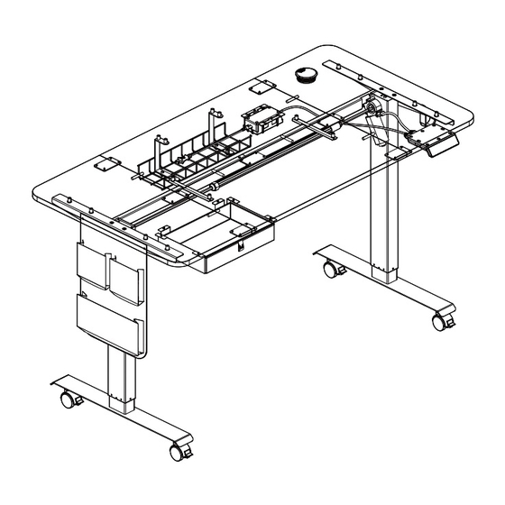
- Page 8 STEP 8: First, insert the power cable into the corresponding interface of the adapter Next, insert the adapter and motor cable into the hand controller first. All cables can be fastened to the desktop by using wire buckles Congratulations, you have completed the basic assembly of the desk. Please test the use of the desk after powering on.
-
Page 9: Hook Installation
Accessories Installation Instructions Hook Installation M6*1*14 Hexagon Socket M4 Allen Wrench M6 Nut Round Head Screw × × × As shown in the picture, first match the hook with the mounting holes on the side board. Then use the M4 allen wrench , one M6*1*14 hexagon socket round head screw , and one M6 nut fix the hook on the side... -
Page 10: Cable Management Installation
Cable Management Installation M4 Allen Wrench M6*1*14 Hexagon Socket Round Head Screw × × As shown in the picture, firstly match the mounting holes of the 2 C-brackets (Pay attention to the direction) to the pre-embedded screw holes on the desktop. Then use the M4 allen wrench and 4 M6*14 hexagon socket round head screws to fix the C-brackets to the... - Page 11 Casters Installation The locking and unlocking of the casters can be controlled by moving the buttons on the casters up and down. M14 Open End Wrench × To use casters , first, turn the rubber pads on the desk feet counterclockwise to remove them, and then use the M14 open end wrench to fix the casters on the desk feet.
- Page 12 Instructions for Hand Controller Set Up Button Height DOWN Memory Heights NOTE 1. Make sure that there are no obstacles and that the desktop is not close to the wall during the lifting process. 2. Before use, please reset and ensure that all power cords are long enough to move the desk up and down. Reset Steps 1.
- Page 13 The following settings are set according to personal preferences. Set Upper Height Limit Start by raising the desk to the desired height. Next, press the M button, and the hand controller will display "S-", release the M button, long-press the up button, and the hand controller will flash once, release the up button, and long-press the M button until the hand controller displays "999", then the upper height limit setting is completed.
- Page 14 Memory Height Inching and Continuation Switching In the reset state, that is, the hand controller shows the "RST". Long press button 1 to switch between memory height inching and memory height continuation. The hand controller displays "10.1", which is the memory height continuation. The hand controller displays "10.2", which is the memory height inching.
-
Page 15: Common Problems And Solutions
Q&A Common Problems and Solutions 1. If the desk has the following problems, try the Reset Steps on Page 12. · Abnormal work. · The hand controller displays RST. · The hand controller displays an error message (E07, E08), but the motor cable is connected fine. 2.
Need help?
Do you have a question about the US-01 and is the answer not in the manual?
Questions and answers