
Related Manuals for Campbell CSAT3B


Summary of Contents for Campbell CSAT3B
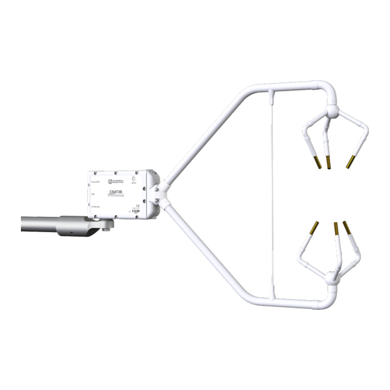
- Page 1 PRODUCT MANUAL CSAT3B 3-D Sonic Anemometer with Integrated Electronics Revision: 04/2023 2023 Copyright © Campbell Scientific CSL I.D - 1062...
- Page 2 Quotations for repairs can be given on request. It is the policy of Campbell Scientific to protect the health of its employees and provide a safe working environment, in support of this policy a “Declaration of Hazardous Material and Decontamination”...
- Page 3 About this manual Please note that this manual was originally produced by Campbell Scientific Inc. primarily for the North American market. Some spellings, weights and measures may reflect this origin. Some useful conversion factors: Area: 1 in (square inch) = 645 mm Mass: 1 oz.
- Page 4 • Periodically (at least yearly) check electrical ground connections. WHILE EVERY ATTEMPT IS MADE TO EMBODY THE HIGHEST DEGREE OF SAFETY IN ALL CAMPBELL SCIENTIFIC PRODUCTS, THE CUSTOMER ASSUMES ALL RISK FROM ANY INJURY RESULTING FROM IMPROPER INSTALLATION, USE, OR MAINTENANCE OF TRIPODS, TOWERS, OR ATTACHMENTS TO TRIPODS AND TOWERS...
-
Page 5: Table Of Contents
Table of contents 1. Introduction 2. Precautions 3. Initial inspection 4. Overview 4.1 Features 4.2 Sensor components 4.2.1 Standard components 4.2.1.1 CM250 levelling mounting kit 4.2.1.2 USB data cable 4.2.2 Sonic carrying case 4.2.3 Common accessories 4.2.3.1 Power and communications cables 4.2.3.2 FW05 thermocouple 4.2.3.3 FWC-L cable 4.2.3.4 Thermocouple cover... - Page 6 6.10 Multiple CSAT3B configurations 6.10.1 CPI communications 6.10.2 RS-485 communications 6.10.3 USB 6.11 Confirm CSAT3B factory settings 7. Operation 7.1 Theory of operation for wind and sonic temperature measurements 7.1.1 Algorithm Version 5 7.1.2 Effects of crosswind on the speed of sound 7.1.3 Sonic transducer shadow correction...
- Page 7 8.2 Sonic wicks 8.3 Desiccant 8.4 Calibration 8.4.1 Test for wind offset 8.5 Troubleshooting 8.5.1 Sending an OS to the CSAT3B 8.6 Returning the CSAT3B 9. References A.1 Determining true north and sensor orientation A.2 Online magnetic declination calculator Appendix B. CSAT3B measurement theory B.1 Theory of operation...
-
Page 8: Introduction
Voltage input must be within a range of 9.5 to 32 VDC. The CSAT3B head should be handled by holding the block at the back of the sensor. Handling it by the arms or transducers could cause geometric deformation, which degrades the measurements. -
Page 9: Initial Inspection
CSAT3B foam case set CM250 leveling mounting kit USB data cable Cables for the CSAT3B, although not included in the standard package, are specified at the time of order and are shipped with the CSAT3B: Either CSAT3BCBL1-L or CSAT3BCBL2-L and CSAT3BCBL3-L 4. -
Page 10: Features
CSAT3B; others are accessories that must be ordered separately. Some common accessories, such as cables, are required to operate a CSAT3B. 4.2.1 Standard components Standard components are items that are included or shipped with the CSAT3B. The following sections describe these items. CSAT3B Three-Dimensional Heated Sonic Anemometer... -
Page 11: Cm250 Levelling Mounting Kit
(p. 4)) that facilitates mounting a CSAT3B at the end of a 3.33 cm (1.31 in) OD crossarm or pipe. The kit includes a captive 3/8-in bolt that screws into the bottom of the CSAT3B block, and a 3/16-in Allen wrench to tighten the adapter on the pipe. -
Page 12: Sonic Carrying Case
CSAT3B in a protected position while providing space for additional components. If the sonic carrying case option is not selected, the CSAT3B will be shipped in a large cardboard box. The same set of foam inserts used in the sonic carrying case is used in the cardboard box to securely hold the CSAT3B. - Page 13 To collect data through another means (such as CPI, RS-485, or USB), the CSAT3BCBL1 Power/SDM cable may still be used to provide power to the CSAT3B, in which case the SDM wires should be left unwired to any ports on the data logger.
-
Page 14: Fw05 Thermocouple
Figure 4-4. Options for CSAT3BCBL2 power cable CPI/RS-485 cable (CSAT3BCBL3) To use CPI or RS-485 communications to collect data from a CSAT3B, the CSAT3BCBL3-L-PT, CSAT3BCBL3-L-RJ, or CSAT3BCBL3-L-MC, should be ordered along with a cable to provide power to the sensor (for example, either the CSAT3BCBL1 or CSAT3BCBL2). -
Page 15: Fwc-L Cable
FW05 and the FWC-L cable. It is used to mount the connectors to the side of the CSAT3B block. It also minimizes temperature gradients across the connectors. 4.2.3.5 Thermocouple cover backplate The CSAT3B fine-wire thermocouple cover backplate attaches to the CSAT3B block and is used to cover the back side of the TC cover. NOTE: The backplate is required for the CSAT3B but not for other Campbell Scientific sonic anemometers. -
Page 16: Fw/Enc Thermocouple Carrying Case
FW/ENC when not in use. Ordering at least a set of four FW05 thermocouples for every CSAT3B is recommended, as the FW05 will break during normal wear and tear in the field. Figure 4-7. FW/ENC for storing fragile thermocouples 4.2.4 Other accessories... -
Page 17: Power/Sdm Splitter
CSAT3BCBL3 cables. The splitter is IP68 rated. It is used for daisy-chaining multiple CSAT3Bs in series that use CPI or RS-485 communications. A splitter is required for each CSAT3B in the daisy chain, except for the terminal one. For a daisy chain of CSAT3Bs using SDM communications, the CPI/RS-485 splitter is not needed;... - Page 18 Figure 4-10. CSAT3B power cable compensation plug The primary indicator of low voltage is in the diagnostic flags returned by the CSAT3B to the data logger. Flag number 32 (0x0020) indicates detection of a low-voltage condition. If the instrument returns flag 32, first measure the power source voltage and ensure that its DC value meets specifications.
-
Page 19: Hub-Sdm8
(p. 12)) allows up to six SDM devices (typically, one data logger and multiple SDM sensors) to be connected in parallel. In the case of the CSAT3B, up to five CSAT3Bs, or CSAT3B daisy chains using CSAT3BCBL1 cables, may be connected to the HUB-SDM8. -
Page 20: Hub-Cpi
The 8-channel RJ45 HUB-CPI allows up to eight CPI devices to be connected in parallel. Up to seven CSAT3Bs, or CSAT3B daisy chains using CSAT3BCBL3 cables, may be connected in parallel to the HUB-CPI. The remaining port may be used with a CAT5e or CAT6 Ethernet cable (see... -
Page 21: Specifications
(such as computer data collection), the output is prompted by the CSAT3B itself. The default operating mode of the CSAT3B is to make measurements when triggered by a data logger (SDM or CPI), which does not apply any low-pass (high-cut) filtering. See Communications (p. - Page 22 2 Hz Inclinometer accuracy: ± 1° Relative humidity accuracy: ± 7% over 0 to 10% range ± 3% over 10 to 90% range ± 7% over 90 to 100% range Board temperature accuracy: ± 2 °C CSAT3B Three-Dimensional Heated Sonic Anemometer...
-
Page 23: Communications
USB: Used for anemometer configuration or computer-based data acquisition. Connection speed: USB 2.0 full speed 12 Mbps Cable length: 5 m max For additional details, refer to Campbell Scientific whitepaper “Designing Physical Network Layouts for the CPI Bus” 5.3 Power requirements Anemometer voltage requirement: 9.5 to 32 VDC... -
Page 24: Physical Description
9.1 kg (20.0 lb) Dimensions: 91 x 51 x 41 cm (36 x 20 x 16 in) Carrying case option Weight: 16.3 (36.0 lb) Dimensions: 81 x 66 x 43 cm (32 x 26 x 17 in) CSAT3B Three-Dimensional Heated Sonic Anemometer... -
Page 25: Installation
CSAT3B. 6.2 Site considerations If the CSAT3B is to be used in a marine environment or in an environment where it is exposed to corrosive chemicals (for example, the sulfur-containing compounds in viticulture), attempt to mount the CSAT3B in a way that reduces exposure of the sonic transducers to saltwater or corrosive chemicals. - Page 26 2. Connect the circular connector on the USB data cable included with the CSAT3B to the port labelled USB on the back of the CSAT3B block. Connect the other end of the cable to a USB port on a computer.
- Page 27 For each setting or status value, the factory default setting is noted by the footnote. Ensure that the appropriate settings are enabled for the communications protocol that will be used. Table 6-1: CSAT3B settings and status values in Device Configuration Utility Setting or status Subscreen...
- Page 28 Table 6-1: CSAT3B settings and status values in Device Configuration Utility Setting or status Subscreen Options Description value 1 through 14 SDM Address Unique address for SDM device 1 through 120 CPI Address Unique address for CPI device Disable Both...
- Page 29 Table 6-1: CSAT3B settings and status values in Device Configuration Utility Setting or status Subscreen Options Description value Mode 0: Data logger triggered | No filter | Data logger prompted output Mode 1: Self triggered | Filtered | Data logger Identifies the source of the...
-
Page 30: Mount The Csat3B
The SDM communications port is always enabled. 6.4 Mount the CSAT3B The CSAT3B is supplied with mounting hardware to attach it to the end of a horizontal pipe with an outer diameter of 3.33 cm (1.31 in), such as the Campbell Scientific CM202, CM204, or CM206 crossarm (referred to generically as a CM20X crossarm). - Page 31 5. Lightly tighten the bolt so that final leveling can be performed once all instrumentation is fully mounted to the structure. CAUTION: Do not carry the CSAT3B by the arms or the strut between the arms. Always hold the CSAT3B by the block, where the upper and lower arms connect. CAUTION: Over-tightening bolts will damage the screw threads in the CSAT3B block.
-
Page 32: Orientation
Figure 6-3. CSAT3B mounting 6.5 Orientation The three components of wind are defined by a right-handed orthogonal coordinate system. The CSAT3B points into the negative x direction (see Figure 6-6 (p. 28)). If the anemometer is pointing into the wind, it will report a positive u wind. - Page 33 Figure 6-4. Right-hand coordinate system, horizontal wind vector angle is 0 degrees Figure 6-5. Compass coordinate system, compass wind direction is 140 degrees CSAT3B Three-Dimensional Heated Sonic Anemometer...
-
Page 34: Levelling
Adjust the anemometer head so that the bubble within the level on top of the CSAT3B block is in the bullseye. Firmly grasp the sonic anemometer block, loosen the bolt underneath the block, and adjust the head accordingly. -
Page 35: Installing Additional Fast-Response Sensors
First, attach the TC cover backplate to the CSAT3B with the screw that was included. Next, attach the socket connector from the FWC-L to the side of the anemometer with the short screw (#2-56 x 0.437 in) that was provided with the white thermocouple cover. - Page 36 Figure 6-7. Exploded view of fine-wire thermocouple (TC) with CSAT3B Figure 6-8. CSAT3B with fine-wire thermocouple mounted CSAT3B Three-Dimensional Heated Sonic Anemometer...
-
Page 37: Other Gas Analyzers
6.7.2 Other gas analyzers If a fast-response gas analyzer is being used with the CSAT3B, care should be taken to mount the analyzer (open-path) or the analyzer intake (closed-path) as close as possible to the sonic sampling volume in order to obtain good spatial and temporal synchronicity between vertical wind and gas concentration fluctuations while also retaining adequate spatial separation. - Page 38 Figure 6-9. Grounding lug of CSAT3B NOTE: If connecting multiple CSAT3Bs together either in a daisy chain series or star topology, each CSAT3B must be separately grounded to either the mounting structure or a grounding rod. CSAT3B Three-Dimensional Heated Sonic Anemometer...
-
Page 39: Communications
(p. 5) for information about ordering cables.) 6.9 Communications If the CSAT3B is going to be operated using SDM or CPI communications where the data logger triggers the measurement and the data is unfiltered (see Mode 0 in Operating modes (p. - Page 40 NOTE: Unlike previous CSAT3 models, the CSAT3B does not include 7.6 m (25 ft) lengths of all cable types. Only the 5 m (16 ft) USB cable for initial configuration of the sensor is included. Other cables must be ordered separately. Table 6-3: Summary of communications options for the CSAT3B...
-
Page 41: Sdm Communications
M16 connector into the port until tight. No other cables are required for SDM communications, as the CSAT3BCBL1 contains both power and SDM wiring. If only one CSAT3B is being measured, the opposite end of the cable will have wire pigtails to connect directly to the ports on a data logger. Refer to Communications (p. - Page 42 Figure 6-10. Power/SDM connections Figure 6-11. Wiring to power and SDM ports on CR6 data logger CSAT3B Three-Dimensional Heated Sonic Anemometer...
- Page 43 (see Operating modes (p. 50) for more details), the CSAT3B Status light will flash red until a data logger is connected to the CSAT3B and its program is running and sending measurement triggers. CSAT3B Three-Dimensional Heated Sonic Anemometer...
-
Page 44: Multiple Csat3B Configurations
SDM address. Connect a CSAT3BCBL1 to the Power/SDM port of the CSAT3B. The opposite end will have an M16 connector that is compatible with one of the split M16 connectors on the Power/SDM splitters. Next, screw the side of the splitter with only one M16 connector to the Power/SDM port of the second CSAT3B. - Page 45 Figure 6-13. SDM daisy chain (CSAT3B sensor arms and grounding cables not shown) CSAT3B Three-Dimensional Heated Sonic Anemometer...
-
Page 46: Cpi Communications
Next, connect a CSAT3BCBL3 to the CPI/RS-485 port in the same manner. If only one CSAT3B is being measured, the opposite end of the power cable should have pigtail wires that may be wired to the 12 V and G terminals on a data logger or to a separate 12 to 32 VDC nominal power... - Page 47 The CPI cable should have the RJ45 connector plugged into the CPI port of the data logger. Figure 6-15. Power and CPI cable connections Figure 6-16. CPI connection to a CR6 data logger CSAT3B Three-Dimensional Heated Sonic Anemometer...
- Page 48 Screw the sides of the splitters with only one M16 connector to the Power/SDM and CPI/RS-485 ports of the second CSAT3B. Connect another set of cables from these splitters down to the next the CSAT3B. Continue the daisy chain until the last CSAT3B, where a final CSAT3BCBL2 should have pigtail wire ends to connect to the 12 V and G terminals of a data logger or to a separate 12...
- Page 49 Figure 6-17. CPI daisy chain (CSAT3B sensor arms and grounding cables not shown) CSAT3B Three-Dimensional Heated Sonic Anemometer...
-
Page 50: Rs-485 Communications
Figure 6-18. CPI star topology (CSAT3B sensor arms and grounding cables not shown) 6.10.2 RS-485 communications If data collection from the anemometer is to be accomplished by a computer using RS-485, first connect the CSAT3B as described in Settings (p. 18) to confirm the following four settings:... - Page 51 Next, connect a CSAT3BCBL3 cable to the CPI/RS-485 port in the same manner. If only one CSAT3B is being measured, the opposite end of the power cable should have pigtail wires, which may be connected to a 9.5 to 32 VDC power supply, and the RS-485 cable should have pigtail...
-
Page 52: Usb
Figure 6-19. RS-485 cable connections 6.10.3 USB If data collection from the anemometer is to be done by a computer using USB communications, first connect to the CSAT3B as described in Settings (p. 18) to confirm the following three settings:... -
Page 53: Confirm Csat3B Factory Settings
Connect the 5 m (16 ft) USB cable included with the CSAT3B to the USB port in the same way. If only one CSAT3B is being measured, the opposite end of the power cable should have pigtail wires, which may be connected to a 9.5 to 32 VDC power supply, and the USB cable should be... -
Page 54: Operation
The time of flight of a sonic signal between a pair of transducers is directly related to the wind vector component that is parallel to the sonic axis. The CSAT3B is able to calculate the wind vector components along each sonic axis using the time difference between an outgoing and return sonic signal, along with the distance between sonic transducers. -
Page 55: Algorithm Version
Each time a significant change has been made to these algorithms, a new version number has been issued. The CSAT3B uses algorithm Version 5. Version 5 maintains many of the advantages of signal recognition and diagnostic sensitivity that were made possible by Version 3, while also adding the advantages of performance during precipitation events made possible by Version 4. -
Page 56: Sonic Transducer Shadow Correction
Figure 7-1 (p. 50)) The CSAT3B embedded code improves the estimates of θ — and therefore the accuracy of the correction — by iteratively applying the preceding correction three times for each measurement of each sonic path. Since debate continues on the appropriateness of this and other shadow corrections in turbulent versus laminar flows, the default of this setting is Disabled. -
Page 57: Operating Modes
CSAT3B operating modes. The following sections give more information on the measurement trigger, data filters, and data output as a guide to selecting the appropriate mode. Mode 0 is the default operating mode for the CSAT3B and is recommended when fluxes are the primary interest. - Page 58 Figure 7-2. Measurement settings in Device Configuration Utility Table 7-1: Overview of CSAT3B operating modes Measurement Trigger Filters Output Prompt Mode Source Rate Enabled Bandwidth (Hz) Source Rate Data logger 1 to 100 Hz 1 to 100 Hz Data logger...
-
Page 59: Measurement Trigger
A measurement trigger is the actual command to initiate a sonic measurement and can be driven by either a data logger or the CSAT3B internal timer. If the trigger is given by a data logger as in Mode 0, then no data filtering is done (bandwidth is wide open) since each trigger will initiate a single new measurement (single-measurement regime). -
Page 60: Csat3B Sonic Data Output
CSAT3B OS versions 1.09 and newer. 7.2.3 CSAT3B sonic data output After a measurement is triggered and optionally run through a filter, it is stored in the CSAT3B data buffer until it is output to either a data logger or a computer. - Page 61 CRBasic instruction in the program scan. When the data logger prompt is received by the CSAT3B, it will output the most recent 100 Hz filtered sample in its buffer to the data logger. This filtered data is delayed by a certain time...
- Page 62 If signatures do not match, the data should be disregarded. The following block of code is an example implementation of the Campbell Scientific signature algorithm in the programming language C. To generate the signature of an output array of bytes, the “seed”...
- Page 63 Table 7-3 (p. 57). Even after accounting for the sample delay, a synchronicity error between the computer and the CSAT3B may still exist, since they each have their own clocks. Table 7-3 (p. 57) shows the possible synchronicity errors for each output rate.
-
Page 64: Operating Mode Recommendations
Due to the advantages in making synchronous measurements, Campbell Scientific recommends using a data logger that supports SDM or CPI communications to collect data from the CSAT3B. If flux measurements are the primary interest, Campbell Scientific further recommends that the CSAT3B be operated in Mode 0 where the data logger triggers the measurements, no filters are applied, and the data is collected by the data logger. -
Page 65: Data Logger Programming Using Sdm Or Cpi
For example, in Mode 1 where data is being filtered and then output is prompted by a data logger, if the data logger has a 10 Hz scan rate and the CSAT3B has been set to use a 5 Hz bandwidth filter, the analogue measurements should be delayed by eight data logger scans (eight 100 ms/scan = 800 ms). -
Page 66: Csat3B()
Destination This variable will store the values returned by the anemometer. The destination variable must be declared as a float (default) with at least five elements. The CSAT3B returns the following data in response to a measurement trigger: — x-axis wind speed in metres per second (m·s —... -
Page 67: Csat3Bmonitor()
Destination This variable will store the values returned by the anemometer. The destination variable must be declared as a float (default) with at least four elements. The CSAT3B returns the following data in response to this instruction: Electronics temperature in degrees Celsius (°C) Electronics relative humidity as a percentage (%) Inclinometer pitch in degrees (°) -
Page 68: Diagnostic Word
The diagnostic word is formatted as a simple 32-bit binary word. Each bit in the diagnostic word represents a different warning flag related to the operation of the CSAT3B. The data logger will display the diagnostic word as a base-10 integer. Viewed in this manner, each of the 32 bits has a different magnitude as a decimal number. -
Page 69: Sdmtrigger()
SDMTrigger() is an SDM Input/Output instruction that controls SDM devices that support the group trigger protocol, including the CSAT3B. Up to 15 group-trigger devices can be connected to the SDM bus. All group-trigger devices are triggered for simultaneous CSAT3B Three-Dimensional Heated Sonic Anemometer... -
Page 70: Programming
8. Maintenance and troubleshooting 8.1 General maintenance With no moving parts, maintenance of the CSAT3B is minimal and limited to the following: Replacing the desiccant canister Monitoring diagnostics and measurement offsets to determine when factory recalibration is needed Monitoring diagnostics to assure battery bank for both 12 and 24 VDC power sources have sufficient charge The following sections address these maintenance activities. -
Page 71: Sonic Wicks
8.2 Sonic wicks Ultrasonic anemometers are unable to measure wind when water droplets completely obscure the face of the transducers. Campbell Scientific algorithm Version 5 along with sonic wicks (shown in Figure 8-1 (p. 65)) improve transducer performance in rainy conditions. Under certain conditions, the wicking properties of the sonic wicks may not be adequate. -
Page 72: Desiccant
To prevent liquid water from coming in contact with any electronics, the internal humidity must be maintained at non-condensing levels. The CSAT3B has an on-board relative humidity sensor that continuously monitors the humidity inside the enclosure. This humidity ranges between 0 and 100%. - Page 73 The CSAT3B has a cavity to hold a replaceable desiccant canister that removes water from the air (see Figure 8-3 (p.
-
Page 74: Calibration
Testing wind offset on a CSAT3B requires creating an environment where wind is absent. Because it is difficult to do this in the field, wind offset data from the CSAT3B should be collected in a field office or the lab. A zero-wind environment can be created with a kitchen waste bin liner. The following steps should be taken to test the CSAT3B for wind offset. - Page 75 Temporarily disable the HVAC system in the room, or cover air vents that may cause air drafts to pass by the CSAT3B. Ensure that the liner does not obstruct any of the three CSAT3B sonic paths.
-
Page 76: Troubleshooting
Figure 8-5. CSAT3B real-time data with 1 sec update and u wind component graphed Graph 1 minute of wind data from the CSAT3B while it is in the zero-wind environment. The wind –1 –1 –1 –1 offset should be less than ±8 cm·s (0.08 m·s... -
Page 77: Sending An Os To The Csat3B
1. Perform a visual inspection of the CSAT3B. Make sure it is clear from anything that might obstruct the sonic signal. Check for signs that the geometry of the arms has changed in any way, possibly from an impact from another object. -
Page 78: Returning The Csat3B
RMA number. If additional help is needed, please contact Campbell Scientific. When preparing the CSAT3B for shipment, be sure to package it in the same foam in which it was sent. If the foam cannot be found, new foam should be ordered from Campbell Scientific before returning the unit. -
Page 79: Determining True North And Sensor Orientation
3. Loosen the u-bolt on the CM220 or the set screws on the Nu-Rail that secure the base of the sensor to the crossarm. While holding the vane position, slowly rotate the sensor base until the datalogger indicates 0 degrees. Tighten the set screws. CSAT3B sonic anemometer... -
Page 80: Online Magnetic Declination Calculator
FIGURE A-1. Magnetic Declination at 2012.5 (degrees relative to true north, positive is east) FIGURE A-2. Declination Angles East of True North are Subtracted from 0 to get True North CSAT3B sonic anemometer... - Page 81 FIGURE A-3. Declination Angles West of True North are Added to 9 to get True North CSAT3B sonic anemometer...
-
Page 82: Appendix B. Csat3B Measurement Theory
B.1 Theory of operation B.1.1 Wind speed Each axis of the CSAT3B pulses two ultrasonic signals in opposite directions. The time of flight of the first signal (out) is given by: Eq. 1 and the time of flight of the second signal (back) is given by: Eq. -
Page 83: Temperature
, and u ) with the following: Eq. 4 where: A = a 3 x 3 coordinate transformation matrix that is unique for each CSAT3B and is stored in ROM memory B.1.2 Temperature The sonically determined speed of sound is given in Eq. -
Page 84: References
The sonic virtual temperature, in degrees Celsius, is given by Eq. 10 (p. 77), where g = 1.4 and R = 287.04 JK Eq. 10 B.2 References Fleagle, R.G. and J.A. Businger. 1980. An Introduction to Atmospheric Physics. New York: Academic Press, Inc. CSAT3B Three-Dimensional Heated Sonic Anemometer... - Page 85 Schotanus, P., F.T.M. Nieuwstadt, and H.A.R. de Bruin. 1983. "Temperature measurement with a sonic anemometer and its application to heat and moisture fluxes." Boundary-Layer Meteorology 26: 81–93. Wallace, J.M. and P.V. Hobbs. 2006. Atmospheric Science: An Introductory Survey. New York: Academic Press. CSAT3B Three-Dimensional Heated Sonic Anemometer...
- Page 86 Campbell Scientific Regional Offices Australia France Thailand Location: Garbutt, QLD Australia Location: Vincennes, France Location: Bangkok, Thailand Phone: 61.7.4401.7700 Phone: 0033.0.1.56.45.15.20 Phone: 66.2.719.3399 Email: info@campbellsci.com.au Email: info@campbellsci.fr Email: info@campbellsci.asia Website: www.campbellsci.com.au Website: www.campbellsci.fr Website: www.campbellsci.asia Brazil Germany Location: São Paulo, SP Brazil...
Need help?
Do you have a question about the CSAT3B and is the answer not in the manual?
Questions and answers