
Related Manuals for Campbell CSAT3B


Summary of Contents for Campbell CSAT3B
- Page 1 CSAT3B Three-Dimensional Sonic Anemometer 2/15 C o p y r i g h t © 2 0 1 5 C a m p b e l l S c i e n t i f i c , I n c .
- Page 3 Limited Warranty “Products manufactured by CSI are warranted by CSI to be free from defects in materials and workmanship under normal use and service for twelve months from the date of shipment unless otherwise specified in the corresponding product manual. (Product manuals are available for review online at www.campbellsci.com.) Products not manufactured by CSI, but that are resold by CSI, are warranted only to the limits extended by the original manufacturer.
- Page 4 SCIENTIFIC, INC., phone (435) 227-9000. After an application engineer determines the nature of the problem, an RMA number will be issued. Please write this number clearly on the outside of the shipping container. Campbell Scientific’s shipping address is: CAMPBELL SCIENTIFIC, INC.
- Page 5 Periodically (at least yearly) check electrical ground connections. • WHILE EVERY ATTEMPT IS MADE TO EMBODY THE HIGHEST DEGREE OF SAFETY IN ALL CAMPBELL SCIENTIFIC PRODUCTS, THE CUSTOMER ASSUMES ALL RISK FROM ANY INJURY RESULTING FROM IMPROPER INSTALLATION, USE, OR MAINTENANCE OF TRIPODS, TOWERS, OR ATTACHMENTS TO TRIPODS AND TOWERS SUCH AS SENSORS, CROSSARMS, ENCLOSURES, ANTENNAS, ETC.
-
Page 7: Table Of Contents
Table of Contents PDF viewers: These page numbers refer to the printed version of this document. Use the PDF reader bookmarks tab for links to specific sections. 1. Introduction ..............1 2. Cautionary Statements ..........1 3. Initial Inspection ............1 4. - Page 8 Desiccant ................... 56 Calibration ..................57 9.4.1 Test for Wind Offset ..............58 Troubleshooting ................60 9.5.1 Sending an OS to the CSAT3B ..........60 Returning the CSAT3B ..............61 10. Reference and Attributions ........61 10.1 References ..................61 Appendices A.
- Page 9 7-12. Power and CPI cable connections ............37 7-13. CPI connection to a CR6 datalogger ..........37 7-14. CPI daisy chain (CSAT3B sensor arms and grounding cables not shown) .................... 39 7-15. CPI star topology (CSAT3B sensor arms and grounding cables not shown) ..................
- Page 10 Proper orientation of sonic top wick (left) and bottom wick (right) .. 56 9-2. Exploded view of CSAT3B desiccant canister ........57 9-3. CSAT3B real-time data with 1 sec update and u and u wind component graphed ................ 59 9-4.
-
Page 11: Introduction
Voltage input must be within range of 9.5 − 32 Vdc • • The CSAT3B head should be handled by holding the block at the back of the sensor. Handling it by the arms or transducers could cause geometric deformation, which degrades the measurements. -
Page 12: Quickstart
CSAT3B using SDM or CPI communications with a Campbell Scientific datalogger. It is intended primarily as an overview and general reference for setup of a CSAT3B, and is not intended as a replacement for the more detailed information on installation found in Section 7, Installation. -
Page 13: Csat3B Mounting
CSAT3B block (FIGURE 4-3). 5. Earth (chassis) ground the other end of the wire to the CSAT3B mounting structure or to a grounding rod. For more details on grounding, see the grounding section of the CR3000 datalogger manual. -
Page 14: Communications Connections
1. Connect power and communication cable(s). SDM Communications If using SDM communications, connect a CSAT3BCBL1-L (“L” denotes the cable length in feet) cable to the connector on the back of the CSAT3B block labeled Power/SDM as shown in FIGURE 4-4. CPI Communications... -
Page 15: Cable Connections For Cpi
If using SDM communications, connect the wire leads on the end of the CSAT3BCBL1-L cable to the datalogger SDM and power ports according to TABLE 4-1. Refer to FIGURE 4-6 which shows these connections to a CR1000 datalogger. TABLE 4-1. Wiring Diagram for CSAT3B with SDM Communications Datalogger Terminal Wire Color 12 V (or other 9.5 to 32 Vdc source) -
Page 16: Sdm And Power Wiring To A Cr1000 Datalogger
CSAT3B Three-Dimensional Sonic Anemometer FIGURE 4-6. SDM and power wiring to a CR1000 datalogger CPI Communications With CPI communications, connect the red and black wires on the end of the CSAT3BCBL2-L-PT to the 12 V and ground terminals of a datalogger or to a 9.5 to 32 Vdc power supply. -
Page 17: Cpi And Power Connections To A Cr6 Datalogger
CPI, for more information on datalogger instructions and programming. 4. Verify that measurements are being made by ensuring the green Status light (FIGURE 4-8) on the CSAT3B block is blinking, indicating that measurements are being made and recorded in the datalogger without diagnostic error conditions. -
Page 18: Factory Settings
CSAT3B Three-Dimensional Sonic Anemometer Factory Settings The CSAT3B is shipped from the factory with the default settings that are shown in TABLE 4-2. These settings can be changed with a PC running Campbell Scientific’s Device Configuration Utility, version 2.10 or newer, and the USB cable that shipped with the CSAT3B. -
Page 19: Features
(FIGURE 5-1) that facilitates mounting a CSAT3B at the end of a 3.33 cm (1.31 in) OD crossarm or pipe. The kit includes a captive 3/8-in bolt that screws into the bottom of the CSAT3B block, and a 3/16-in Allen wrench to tighten the adapter on the pipe. -
Page 20: Usb Data Cable
If opting out of the sonic carrying case, the CSAT3B will be shipped in a large cardboard box. The same set of foam inserts used in the sonic carrying case is used in the cardboard box to securely hold the CSAT3B. -
Page 21: Common Accessories
5.2.3.1 Power and Communications Cables Cables required for the CSAT3B to be functional, must be ordered along with the CSAT3B. The types of cables needed for a specific communications mode, are outlined below. -
Page 22: Options For Csat3Bcbl1 Power/Sdm Cable
FIGURE 5-3. Options for CSAT3BCBL1 Power/SDM cable Power Cable (CSAT3BCBL2) To use CPI, RS-485, or USB communications to collect data from a CSAT3B, the CSAT3BCBL2-L-PT or CSAT3BCBL2-L-MC should be ordered to provide power to the sensor. A second cable to transmit the communications is also required (for example, CSAT3BCBL3 CPI/RS-485 cable for CPI or RS-485, or the 30179 USB data cable). -
Page 23: Fw05 Thermocouple
The FW05 is a Type E thermocouple with a 0.0127 mm (0.0005 in) diameter (FIGURE 5-6). The thermocouple measures atmospheric temperature fluctuations and may be used with the CSAT3B to directly calculate sensible heat flux. Larger size fine-wire thermocouples, such as the FW1 and FW3, which are more robust but have slower response times, may also be used with the CSAT3B. -
Page 24: Thermocouple Cover Backplate
FW/ENC when not in use. It is also recommended to order, at a minimum, a set of four FW05 thermocouples for every CSAT3B as the FW05 will break during normal wear and tear in the field. -
Page 25: Power/Sdm Splitter
The HUB-SDM8 (pn 20759) allows up to six SDM devices (typically, one datalogger and multiple SDM sensors) to be connected together in parallel. It is shown in FIGURE 5-10. In the case of the CSAT3B, up to five CSAT3Bs, or CSAT3B daisy-chains using CSAT3BCBL1 cables, may be connected to... -
Page 26: Sdm Cable Cable5Cbl-L
5.2.4.5 HUB-CPI The HUB-CPI (pn 30692) allows up to eight CPI devices to be connected together in parallel. In the case of the CSAT3B, up to seven CSAT3Bs, or CSAT3B daisy-chains using CSAT3BCBL3 cables, may be connected in parallel to the HUB-CPI. The remaining port may be used with a CAT5e or CAT6 Ethernet cable (see Section 5.2.4.4, SDM Cable CABLE5CBL-L) to... -
Page 27: Cat6 Ethernet Cable
CPI to the CPI port on a datalogger such as the CR6. FIGURE 5-12. CAT6 Ethernet cable Specifications The CSAT3B measures wind speed and the speed of sound along the three non-orthogonal sonic axes. The wind speeds are then transformed into the orthogonal wind components u... -
Page 28: Measurements
When self-triggering, the CSAT3B will make measurements at a high rate and provide the latest output upon receiving each datalogger trigger. In either operating mode, various filters can be applied to the output samples to limit the bandwidth of the output data. -
Page 29: Communications
CSAT3B Three-Dimensional Sonic Anemometer Internal Monitor Measurements Update Rate: 2 Hz Inclinometer Accuracy: ± 1 ° Relative Humidity Accuracy: ± 3% over 10 − 90% range ± 7% over 0 − 10% range ± 7% over 90 − 100% range Board Temperature Accuracy: ±... -
Page 30: Physical Description
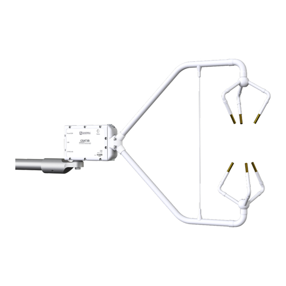
CSAT3B Three-Dimensional Sonic Anemometer Physical Description Dimensions Anemometer Overall: 60.7 cm (23.9 in) length 43.0 cm (16.9 in) height 12.2 cm (4.8 in) width Measurement Path: 10.0 cm (3.9 in) vertical 5.8 cm (2.3 in) horizontal Transducer Angle: 60 degrees from horizontal Transducer Diameter: 0.64 cm (0.25 in) -
Page 31: Installation
1. Provide power to the CSAT3B by connecting the M16 connector of either a CSAT3BCBL1 or CSAT3BCBL2 to the Power/SDM port on the back of the CSAT3B block. The other end of this cable will have red and black wire leads that should be connected to a 9.5 to 32 Vdc power source. -
Page 32: Connecting Csat3B Using Device Configuration Utility
Select the appropriate communication port and baud rate (refer to the left side of FIGURE 7-1). 5. If this is the first time this PC has connected to a CSAT3B and depending on the PC settings, the USB driver may need to be manually installed. -
Page 33: Csat3B Settings And Status Values In Device Configuration
Ensure that the appropriate settings are enabled for the communication protocol that will be used. An example subscreen is shown in FIGURE 7-2. TABLE 7-1. CSAT3B Settings and Status Values in Device Configuration Utility Setting or Status Subscreen Value... - Page 34 CSAT3B Three-Dimensional Sonic Anemometer TABLE 7-1. CSAT3B Settings and Status Values in Device Configuration Utility Setting or Status Subscreen Value Options Description 10 Hz Unprompted 20 Hz Identifies the rate at which to output Output Rate 50 Hz unprompted data...
-
Page 35: Orientation
Section 7.4, Leveling. Mounting The CSAT3B is supplied with mounting hardware to attach it to the end of a horizontal pipe with an outer diameter of 3.33 cm (1.31 in), such as the Campbell Scientific CM202, CM204, or CM206 crossarm (referred to generically as a CM20X crossarm). -
Page 36: Cm210 Mounting Kit With Cm20X Crossarm
3/16-in hex socket head wrench. Refer to FIGURE 7-4. 4. Attach the CSAT3B to the leveling mount by inserting the bolt on the mount into the threaded hole on the bottom of the CSAT3B block as shown in FIGURE 7-4. -
Page 37: Leveling
CSAT3B can give pitch and roll measurements. Pitch is the rotation about the CSAT3B y-axis and is given by the smallest angle between the CSAT3B x-axis (see FIGURE 7-5) and a horizontal plane. A positive pitch angle corresponds to a clock-wise rotation about the y-axis when looking down on the y-axis. -
Page 38: Additional Fast-Response Sensors
CSAT3B wind measurements. The outputs of the CSAT3B integrated inclinometer can be viewed by connecting the USB data cable (pn 30179) to the CSAT3B and a PC computer running Campbell Scientific’s Device Configuration Utility. It can also be output using the CRBasic instruction CSAT3BMonitor. See Section 8.4.1.2, CSAT3BMonitor(), for more information about setting this instruction. -
Page 39: Exploded View Of Fine-Wire Thermocouple With Csat3B
CSAT3B Three-Dimensional Sonic Anemometer First, attach the TC cover backplate to the CSAT3B with the screw that was included. Next, attach the female connector from the FWC-L to the side of the anemometer with the short screw (#2-56 x 0.437in, pn 3514) that was provided with the white thermocouple cover (pn 10080). -
Page 40: Other Gas Analyzers
Wiring On the back of the CSAT3B block there is a copper grounding lug (refer to FIGURE 4-3). Use a standard flat-head screwdriver to pinch an 8 AWG to 14 AWG wire between the lug and the lug screw. Campbell Scientific offers a 10 AWG copper wire (pn 4335) that is suitable for grounding sensors. -
Page 41: Communications
(see Section 5.2.3.1, Power and Communications Cables, for information about ordering cables). If the CSAT3B is going to be operated using SDM or CPI communications where the datalogger triggers the measurement and the data are unfiltered (see Mode 1 in Section 8.2, Operating Modes), then the CSAT3B default settings... -
Page 42: Sdm Communications
FIGURE 7-8. No other cables are required for SDM communications, as the CSAT3BCBL1 contains both power and SDM wiring. If only one CSAT3B is being measured, the opposite end of the cable will have wire pigtails if connecting directly to the ports on a datalogger. Refer to Section 4.2, Communications Connections, for this wiring. -
Page 43: Sdm/Power Connections
CSAT3B Three-Dimensional Sonic Anemometer FIGURE 7-8. SDM/Power connections FIGURE 7-9. Wiring to power and SDM ports on CR1000 datalogger... - Page 44 For an application that requires SDM communications from multiple CSAT3Bs in series, or with a daisy-chain topology, first connect to each CSAT3B as described in Section 7.1, Settings, to ensure each sensor has been assigned a unique SDM address. Connect a CSAT3BCBL1 to the Power/SDM port of the terminal CSAT3B.
-
Page 45: Sdm Daisy Chain
CSAT3B Three-Dimensional Sonic Anemometer FIGURE 7-10. SDM daisy chain (CSAT3B sensor arms and grounding cables not shown) -
Page 46: Cpi Communications
Next, connect a CSAT3BCBL3 to the CPI/RS-485 port in the same manner. If only one CSAT3B is being measured, the opposite end of the power cable should have pigtail wire leads which may be wired to the 12 V and G terminals on a datalogger or to another 12 to 32 Vdc power supply. - Page 47 CSAT3B Three-Dimensional Sonic Anemometer FIGURE 7-12. Power and CPI cable connections FIGURE 7-13. CPI connection to a CR6 datalogger...
- Page 48 CSAT3BCBL2 cable to each Power/SDM port of each CSAT3B, and connect the other wire leads to the 12 V and G ports of a datalogger or to another 12 to 32 Vdc power supply (for convenience, it’s possible to use a wiring bus such as the HUB-SDM8 to bring...
-
Page 49: Cpi Daisy Chain
CSAT3B Three-Dimensional Sonic Anemometer FIGURE 7-14. CPI daisy chain (CSAT3B sensor arms and grounding cables not shown) -
Page 50: Rs-485 Communications
FIGURE 7-15. CPI star topology (CSAT3B sensor arms and grounding cables not shown) 7.7.3 RS-485 Communications If data collection from the anemometer is to be accomplished by a PC using RS-485, first connect the CSAT3B as described in Section 7.1, Settings, to confirm the following settings:... - Page 51 Next, connect a CSAT3BCBL3 cable to the CPI/RS-485 port in the same manner. If only one CSAT3B is being measured, the opposite end of the power cable should have pigtail wire leads, which may be connected to a 12 to 32 Vdc power supply, and the RS-485 cable should have pigtail wire leads for wiring to a connector on a PC (see FIGURE 7-16).
-
Page 52: Usb
Connect the 5 m (16 ft) USB cable included with the CSAT3B to the USB port in the same way. If only one CSAT3B is being measured, the opposite end of... -
Page 53: Operation
The CSAT3B is able to calculate the wind vector components along each sonic axis using the time difference between an outgoing and return sonic signal, along with the distance between sonic transducers. -
Page 54: Algorithm Version 5
CSAT3B is able to output a measurement of sonic air temperature from which actual air temperature may be calculated if humidity is known. For more complete details on the theory of operation of the CSAT3B, refer to Appendix B, CSAT3B Measurement Theory. 8.1.1 Algorithm Version 5... -
Page 55: Operating Modes
The following sections give more information on the measurement trigger, data filters, and data output as a guide to selecting the appropriate mode. Mode 1 is the default operating mode for the CSAT3B and is recommended when fluxes are the primary interest. -
Page 56: Measurement Trigger
A measurement trigger is the actual command to initiate a sonic measurement and can be driven by either a datalogger or the CSAT3B internal timer. If the trigger is given by a datalogger as in Mode 1, then no data filtering is done (bandwidth is wide open) since each trigger will initiate a single new measurement (single-measurement regime). -
Page 57: Data Output
8.2.3 Data Output After a measurement is triggered and optionally run through a filter, it is stored in the CSAT3B data buffer until it is output to either a datalogger or a PC. Mode 1 In the case where a datalogger provides the measurement trigger (Mode 1), the trigger is issued each time the datalogger goes through a scan of the program and executes the CSAT3B() CRBasic instruction. - Page 58 TABLE 8-3. Modes 3 and 4 If the CSAT3B measurements are to be self-triggered and output to a PC, as in Modes 3 and 4, an unprompted output operating mode should be selected. Available output rates for the CSAT3B are 10, 20, 50, or 100 Hz. In...
- Page 59 In most situations, a PC computes the signature by reading in the ASCII data and extracting the last four ASCII characters, casting them as Long data type. The signature is then calculated on the data sent from the CSAT3B, starting with u and ending with the counter.
-
Page 60: Operating Mode Recommendations
Synchronization with other sensors As there is a delay between the CSAT3B’s measurement and output to a datalogger or PC (see TABLE 8-2), the CSAT3B data will be slightly older than the record’s timestamp (recall that the timestamp is assigned to the record by the datalogger or PC). -
Page 61: Datalogger Programming Using Sdm Or Cpi
TABLE 8-4 shows the measurement lags that should be applied to analog measurements or measurements with no delay in order to align them with CSAT3B data. The lags shown for Modes 2 and 4, indicate the number of output scans that the analog measurements should be delayed. -
Page 62: Crbasic Instructions
CSAT3B() The CSAT3B() instruction is the primary instruction used to retrieve anemometer data from the CSAT3B. This will set the operating mode of the anemometer and retrieve the wind, sonic temperature, and diagnostic information. The instruction requires four parameters which are further... -
Page 63: Diagnostic Word
The diagnostic word is formatted as a simple 32-bit binary word. Each bit in the diagnostic word represents a different warning flag related to the operation of the CSAT3B. The datalogger will display the diagnostic word as a base-10 integer. Viewed in this manner, each of the 32 bits has a different magnitude as a decimal number. -
Page 64: Sdmtrigger()
8.4.3 SDMTrigger() The SDMTrigger() is an SDM Input/Output instruction that controls SDM devices that support the group trigger protocol, including the CSAT3B. Up to 15 group-trigger devices can be connected to the SDM bus. All group-trigger devices are triggered for simultaneous measurements with the SDMTrigger. -
Page 65: Maintenance And Troubleshooting
CSAT3B Three-Dimensional Sonic Anemometer Maintenance and Troubleshooting General Maintenance With no moving parts, maintenance of the CSAT3B is minimal and limited to the following: • Replacing rain wicks Replacing the desiccant canister • Monitoring diagnostics and measurement offsets to determine when •... -
Page 66: Desiccant
This can be done automatically with a datalogger if the datalogger program uses the CSAT3BMonitor() instruction in CRBasic, or manually by connecting a CSAT3B to a PC using the USB cable and then launching the Device Configuration Utility. Under the Settings... -
Page 67: Calibration
FIGURE 9-2. Exploded view of CSAT3B desiccant canister Calibration The CSAT3B is calibrated at the factory over the temperature range of −30 to 50 °C, as sonic transducer response is a function of temperature. Any measurements taken at temperatures outside of this range will be suspect. -
Page 68: Test For Wind Offset
Because it is difficult to do this in the field, wind offset data from the CSAT3B should be collected in a field office or the lab. A zero-wind environment can be created with a kitchen waste bin liner. The following steps should be taken to test the CSAT3B for wind offset. -
Page 69: Csat3B Real-Time Data With 1 Sec Update And U X
CSAT3B Three-Dimensional Sonic Anemometer FIGURE 9-3. CSAT3B real-time data with 1 sec update and u and u wind component graphed FIGURE 9-4. CSAT3B real-time data with 1 sec update and u wind component graphed... -
Page 70: Troubleshooting
CSAT3B Three-Dimensional Sonic Anemometer Graph 1 minute of wind data from the CSAT3B while it is in the zero wind environment. The wind offset should be less than ± 8 cm·s (0.08 m·s ) for u –1 –1 and u , and less than ±... -
Page 71: Returning The Csat3B
CSAT3B Three-Dimensional Sonic Anemometer 3. After connecting to the CSAT3B, click on the Send OS tab at the top of the Device Configuration Utility main screen. Click on the Start button at the bottom of the page, select the .obj file that you downloaded from the Campbell website, and click Open. - Page 72 CSAT3B Three-Dimensional Sonic Anemometer Schotanus, P., Nieuwstadt, F. T. M. and de Bruin, H. A. R.: 1983, “Temperature Measurement with a Sonic Anemometer and its Application to Heat and Moisture Fluxes”, Boundary-Layer Meteorol., 26, 81-93. Burns, S. P., Horst, T. W., Jacobsen, L., Blanken P. D. and Monson, R. K.: 2012, “Using sonic anemometer temperature to measure sensible heat flux in...
-
Page 73: Csat3B Orientation
Appendix A. CSAT3B Orientation A.1 Determining True North and Sensor Orientation The orientation of the CSAT3B negative x-axis is found by reading a magnetic compass and applying the site-specific correction for magnetic declination; where the magnetic declination is the number of degrees between True North and Magnetic North. -
Page 74: A Declination Angle East Of True North (Positive) Is Subtracted From 360 (0) Degrees To Find True North
Appendix A. CSAT3B Orientation Declination angles are always subtracted from the compass reading to find True North. A declination angle East of True North is reported as positive a value and is subtracted from 360 (0) degrees to find True North as shown FIGURE A-2. -
Page 75: Online Magnetic Declination Calculator
Appendix A. CSAT3B Orientation A.2 Online Magnetic Declination Calculator The magnetic declination calculator web calculator published by NOAA’s Geophysical Data Center is available at the following URL: www.ngdc.noaa.gov/geomag-web/#declination. After the web page loads, enter the zip code, country and city, or latitude and longitude of the site, then click on Calculate to get the declination for that site (FIGURE A-4). - Page 76 Appendix A. CSAT3B Orientation FIGURE A-5. NOAA magnetic calculator results The declination for Salt Lake City, UT is 11.7 ° (4 November, 2014). As shown in FIGURE A-5, the declination for Utah is positive (east of north), so true north for this site is 360 – 11.7, or 348.3 °. The annual change is –7.8...
-
Page 77: Csat3B Measurement Theory
Theory B.1 Theory of Operation B.1.1 Wind Speed Each axis of the CSAT3B pulses two ultrasonic signals in opposite directions. The time of flight of the first signal (out) is given by: (B-1) and the time of flight of the second signal (back) is given by:... -
Page 78: Temperature
The sonically determined speed of sound is given in Eq. (B-5) and was found from the sum of the inverses of Eq. (B-1) and (B-2). The CSAT3B corrects online for the effect of wind blowing perpendicular to the sonic path. No additional off-line corrections are required as suggested by Liu et al., 2001. -
Page 79: References
Appendix B. CSAT3B Measurement Theory Substitute Eq. (B-7a) and (B-7b) into (B-6) and ignore the higher order terms. This yields γ γ 1 0 51 d d s (B-8) where: = sonic virtual temperature = ratio of specific heat of dry air at constant pressure to γ... - Page 80 Appendix B. CSAT3B Measurement Theory...
-
Page 81: Example Crbasic Datalogger Programs
Sample (5,CSATVals(1),IEEE4) EndTable DataTable (MonitorData,1,-1) DataInterval (0,5,Sec,10) Sample (4,CSATMonitorVals(1),IEEE4) EndTable '--------------------------------------------- ' Main Program '--------------------------------------------- BeginProg Scan(50,msec,500,0) '20 Hz Scan 'CSAT3B(Destination, Bus, Address, OperatingMode) CSAT3B(CSATVals(),0,SDM_ADDR,0) CallTable(SonicData) NextScan SlowSequence Scan(5,sec,0,0) '5 second scan 'CSAT3BMonitor (Destination, Bus, Address) CSAT3BMonitor(CSATMonitorVals(),0,SDM_ADDR) CallTable(MonitorData) NextScan EndProg... -
Page 82: Simple Cpi Program
DataTable (SonicData,1,-1) Sample (5,CSATVals(1),IEEE4) EndTable DataTable (MonitorData,1,-1) DataInterval (0,5,Sec,10) Sample (4,CSATMonitorVals(1),IEEE4) EndTable '--------------------------------------------- ' Main Program '--------------------------------------------- BeginProg Scan(50,msec,500,0) '20 Hz Scan 'CSAT3B(Destination, Bus, Address, OperatingMode) CSAT3B(CSATVals(),1,CPI_ADDR,0) CallTable(SonicData) NextScan SlowSequence Scan(5,sec,0,0) '5 second scan 'CSAT3BMonitor(Destination, Bus, Address) CSAT3BMonitor(CSATMonitorVals(),1,CPI_ADDR) CallTable(MonitorData) NextScan EndProg... -
Page 83: Advanced Cpi Program
{+y} 'The program computes the compass wind direction, using the constant 'CSAT3B_AZIMUTH, and a CSAT3B wind direction. Good CSAT3B wind directions 'are between -90 to 0 and 0 to 90 degrees, e.g. the wind is blowing into 'the CSAT3B sensor head. - Page 84 Alias diag_bits(9) = Flag_TrigErr 'Trigger Error Flag 'Wind directions and speed. Public wind_out(8) 'Alias wind_out(1) = wind_spd - in compass coord system, same as CSAT3B 'Alias wind_out(2) = result_wind_speed - in compass coord system, same as CSAT3B Alias wind_out(3) = wind_dir_compass...
- Page 85 Totalize (1,N_STATS,IEEE4,NOT (Flag_TrigErr) OR NOT (disable_stats(2))) FieldNames ("Flag_TrigErr_Tot") Average (1,panel_temp,IEEE4,FALSE) Average (1,battery_volt,IEEE4,FALSE) Average (1,board_temp,IEEE4,FALSE) Average (1,board_humidity,IEEE4,FALSE) Average (1,incline_pitch,IEEE4,FALSE) Average (1,incline_roll,IEEE4,FALSE) EndTable '--------------------------------------------- ' Main Program '--------------------------------------------- BeginProg Move (Ux,5,NaN,1) 'Set all CSAT3B variables to NaN CPISpeed (CPI_RATE) 'Set the SDM clock speed Scan (SCAN_INTERVAL,mSec,500,0)
- Page 86 'Measure datalogger panel temperature Battery (battery_volt) 'Measure battery voltage. 'CSAT3B(Destination, Bus, Address, OperatingMode) CSAT3B(wind(),1,CPI_ADDR,0) 'Copy and convert CSAT3B for compass wind vector computation. wind_east = -1*Uy wind_north = Ux 'Break up the warning flags into separate bits. diag_integer = diag diag_bits(1) = diag_integer AND &h00000001...
- Page 88 • info@campbellsci.com.cn • info@campbellsci.de www.campbellsci.com www.campbellsci.de Campbell Scientific do Brasil Ltda. (CSB) Campbell Scientific Spain, S. L. (CSL Spain) Rua Apinagés, nbr. 2018 ─ Perdizes Avda. Pompeu Fabra 7-9, local 1 CEP: 01258-00 ─ São Paulo ─ SP 08024 Barcelona...
Need help?
Do you have a question about the CSAT3B and is the answer not in the manual?
Questions and answers