Table of Contents
Advertisement
Quick Links
Advertisement
Table of Contents

Related Manuals for Campbell SkyVUE 8


Summary of Contents for Campbell SkyVUE 8
- Page 1 Revision: 08/2020 Copyright © 2019 – 2020 Campbell Scientific CSL I.D - 1301...
- Page 3 Quotations for repairs can be given on request. It is the policy of Campbell Scientific to protect the health of its employees and provide a safe working environment, in support of this policy a “Declaration of Hazardous Material and Decontamination”...
- Page 5 Campbell Scientific Ltd can advise on the recycling of the equipment and in some cases arrange collection and the correct disposal of it, although charges may apply for some items or territories.
- Page 7 • Periodically (at least yearly) check electrical ground connections. WHILE EVERY ATTEMPT IS MADE TO EMBODY THE HIGHEST DEGREE OF SAFETY IN ALL CAMPBELL SCIENTIFIC PRODUCTS, THE CUSTOMER ASSUMES ALL RISK FROM ANY INJURY RESULTING FROM IMPROPER INSTALLATION, USE, OR MAINTENANCE OF TRIPODS, TOWERS, OR ATTACHMENTS TO TRIPODS AND TOWERS...
-
Page 9: Table Of Contents
3. Initial preparation and checks 4. Installation 4.1 Location and orientation 4.2 Grounding 4.3 Mounting the SkyVUE 8 4.4 Tilt angle 4.5 Connectors and wiring 4.5.1 Base connectors 4.5.2 Wiring using supplied Campbell Scientific cables Table of Contents - i... - Page 10 4.6 Connecting the back-up battery 4.7 Bird spike kit 4.8 Storage information 5. Operation 5.1 Terminal mode 5.1.1 Entering/exiting the SkyVUE 8 terminal mode 5.1.2 Terminal mode commands general 5.1.3 Terminal mode command examples 5.1.4 Application command message types 5.1.5 MCFG command message types 5.1.6 Measurement and message intervals...
- Page 11 FIGURE 4-5. USB port FIGURE 4-6. Connecting battery FIGURE 4-7. Ceilometer bird spike kit installed FIGURE 4-8. Preparing the SkyVUE 8 for installing the bird spikes FIGURE 4-9. Attaching bird spikes to the SkyVUE 8 cowl FIGURE 5-1. Restoring factory defaults FIGURE 5-2.
- Page 12 Table 4-3: Function of the connector pins for the communications connector Table 5-1: Summary of the terminal mode commands available Table 5-2: Summary of applications and applied settings for SkyVUE 8 Table 5-3: Summary of message ID and descriptions Table 6-1: Most significant alarm word for CS messages...
-
Page 13: General Information
1.1 Packing list 1.2 General safety 1.3 Sensor unit safety 1.4 Laser safety 1.5 Electrical safety 1.1 Packing list The following table lists the products shipped with the SkyVUE 8. Table 1-1: Packing list Description Quantity Ceilometer Power supply cable... -
Page 14: Sensor Unit Safety
Ensure that the correct voltage supply is provided to the sensor. 1.4 Laser safety The SkyVUE 8 sensor incorporates an InGaAs laser diode which is rated as a class 3B device. This is an embedded laser where the output from the sensor unit, through the optics, is minimized to class 1M. - Page 15 IEC/EN 60825-1:2014 WARNING: Removing the laser module with the power applied to the SkyVUE 8 or battery connected may expose the user to hazardous class 3B laser radiation. No attempt should be made to operate the laser module outside of the housing.
-
Page 16: Electrical Safety
FIGURE 1-1. Location of laser warning label Before removing the laser module, the sensor must be disconnected from both the mains supply and the battery to ensure that the laser is turned off. 1.5 Electrical safety Because the sensor is powered from potentially hazardous mains voltages, the power-supply should be wired only by personnel qualified to install electrical equipment. -
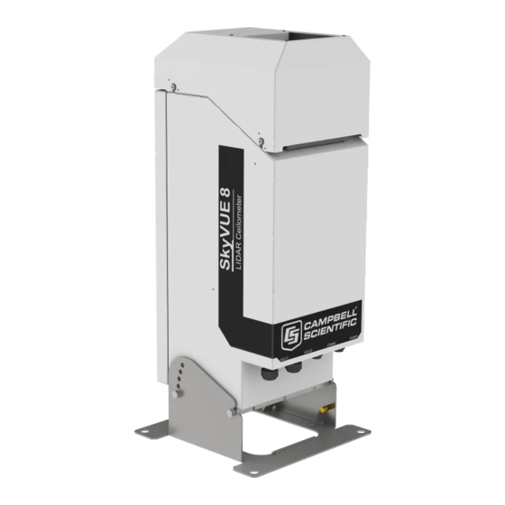
Page 17: Product Overview
The SkyVUE 8 has electrical and laser warning labels on the exterior and interior of the unit. It is fitted with a hex-key access panel. It is recommended that the hood and access panel door are not opened in conditions of rain, hail or snow. -
Page 18: Introduction
The control system of the SkyVUE 8 is divided into three modules, DSP, TOP and PSU as follows: DSP (Digital Signal Processor) is the main data processing and communications unit of the SkyVUE 8. -
Page 19: Sky Condition
Sky condition is an assessment of cloud cover measured in units of eighths known as oktas. The number of oktas is the density of cloud in eighths of that layer. The SkyVUE 8 can report up to five layers of cloud when reporting sky condition. The algorithm used in the SkyVUE 8 follows guidance in the ICAO 9837, Manual on Automatic Meteorological Observing Systems at Aerodromes. -
Page 20: Optical Measurement
2.2 Optical measurement FIGURE 2-1. Principle of operation 2.2.1 Optical arrangement The SkyVUE 8 uses a single biaxial lens design that increases optical signal-to-noise ratio, while maintaining Class 1M eye safety by integrating larger optics into a compact package (see FIGURE (p. -
Page 21: Specifications
2.4 Specifications 2.4.1 Measurement specifications 2.4.2 Mechanical specifications 2.4.3 Electrical specifications 2.4.4 Optical specifications 2.4.5 Environmental specifications 2.4.6 Communications specifications 2.4.7 Compliance and testing 2.4.1 Measurement specifications Maximum reporting range: 8 km (26,250 ft) Minimum reporting resolution: 5 m (15 ft) Hard target range accuracy: ±... -
Page 22: Electrical Specifications
10 to 40 VDC input; 1 A at 12 VDC; 0.5 A at 24 VDC 12V OUT: 12 VDC / 1.7 A for optional or external equipment (if the SkyVUE 8 is using a DC supply, this must be greater than 14 VDC for this to be available .) Heater: Input not used with AC heaters. -
Page 23: Figure 2-3. Psu Types
PSU fuse: HBC 5A (T) All fuses are 5 x 20 mm slow blow (T) and are the same for both 115 VAC and 230 VAC. Battery: Internal 12 V, 7 Ah sealed lead-acid battery. The power supply is equipped with a system to prevent deep discharge of the battery. -
Page 24: Optical Specifications
2.4.4 Optical specifications Pulse duration: 100 ns Pulse frequency: 10 kHz Wavelength: 912 ± 5 nm Half-angle laser divergence: 0.44 mrad Field of view: 2.0 mrad Laser lifetime: 10 years typical Eye safety class: 2.4.5 Environmental specifications Standard operating temperature range: –40 to 60 °C (excluding battery) Battery temperature range: –20 to 50 °C (alternative battery types available) -
Page 25: Compliance And Testing
Signal voltage levels: Minimum value Nominal value Maximum value RS-232 communications RS-232 input threshold low 0.8 V 1.5 V – RS-232 input threshold high – 2.0 V 2.4 V RS-232 input absolute maximum –15 V – +15 V RS-232 input resistance 12 KΩ... -
Page 26: Initial Preparation And Checks
3. Initial preparation and checks The following steps will provide basic familiarization with the SkyVUE 8 and perform basic functionality checks. To do these, open the door and connect the battery (see Connecting the back-up battery (p. 22)). WARNING: The laser begins operating as soon as the battery is connected. Do not point the laser in any direction where it could be viewed with magnifying optics. -
Page 27: Installation
However, there are a few considerations to take into account if accurate and representative data from a site are to be obtained. To reduce the service frequency with the unit, place the SkyVUE 8 away from sources of contamination. More regular maintenance will be required when the instrument is placed in areas where contamination is unavoidable or where measurements may be safety related. -
Page 28: Mounting The Skyvue
4.3 Mounting the SkyVUE 8 Mount the SkyVUE 8 by bolting to a firm, level foundation. When bolting down, ensure the SkyVUE 8 can tilt in all desired directions. FIGURE 4-1 (p. 16) shows the mounting footprint. If a suitable surface does not already exist, construct a concrete foundation, at least 600 mm (23.6 in) square and 600 mm (23.6 in) deep, by using the following procedure:... -
Page 29: Tilt Angle
4.4 Tilt angle The SkyVUE 8 can be tilted 6°, 12°, 18° or 24° from vertical. In tropical regions, tilting the sensor north in the northern hemisphere and south in the southern hemisphere can prevent the sun from shining directly into the sensor. The tilt angle also can reduce problems caused by direct specular reflections from ice crystals, and prevent rain or snow from falling onto the window. -
Page 30: Connectors And Wiring
4.5.3 USB connection 4.5.4 I/O connection 4.5.1 Base connectors The SkyVUE 8 has two connectors on its base. One connector (6 pins) is for communications; another connector (4 pins) provides power to the unit. NOTE: Tilting the unit provides better access to these connectors. -
Page 31: Wiring Using Supplied Campbell Scientific Cables
Z/TXD White A/D– inverting A/RXD Blue inverting Screen 4.5.2 Wiring using supplied Campbell Scientific cables Two cables are supplied, each 10 m (32.8 ft) long. One is for the mains power supply and the other is for communications. SkyVUE™8 (CS136) LIDAR Ceilometer... -
Page 32: Power Connections
WARNING: Incorrectly wiring the power cable can cause irrevocable damage to the unit and can cause serious injury or death. WARNING: The power cable must not be carrying mains voltage when it is being connected or disconnected. 4.5.2.1 Power connections The following is a guide for wiring and installing a permanent power supply. -
Page 33: Communications Connections
5 A at the rated voltage. If this is done, the earth wire of the sensor must be connected to a suitable protective earth point. For DC operation, the SkyVUE 8 requires a 10 to 40 VDC supply capable of 1 A at 12 VDC or 0.5 A at 24 VDC. -
Page 34: I/O Connection
The I/O port is only used for factory setting of the instrument. 4.6 Connecting the back-up battery The SkyVUE 8 is shipped with the back-up battery disconnected and includes desiccant used for transport. Before using the unit, open the door, connect the internal battery (FIGURE 4-6 (p. -
Page 35: Bird Spike Kit
4.7 Bird spike kit The optional bird spike kit deters birds from sitting on the SkyVUE 8. It includes four stainless- steel spikes with rounded ends and a small reel of stainless-steel wire. The following figure shows installed bird spikes. -
Page 36: Storage Information
Check the wire during maintenance and replace if necessary. 4.8 Storage information Store the SkyVUE 8 in a dry place at –40 to 70 °C, preferably with the enclosures securely fastened. Protect the optics from possible accidental damage. Disconnect the back-up battery when storing the SkyVUE 8. -
Page 37: Operation
NOTE: Storing the SkyVUE 8 below 0.0 °C will increase the start-up time by up to ten minutes. At –20 °C, the SkyVUE 8 will not achieve full accuracy for an hour. NOTE: Remove the battery if the SkyVUE 8 is to be stored outside the –20 to 50 °C temperature range. -
Page 38: Entering/Exiting The Skyvue 8 Terminal Mode
Stop bits Flow control none none The baud rate of the SkyVUE 8 must match the port setting baud rate in the terminal emulator. The SkyVUE 8 should now be ready to accept commands. SkyVUE™8 (CS136) LIDAR Ceilometer... -
Page 39: Terminal Mode Command Examples
Example 1 The following text shows an example of setting up the SkyVUE 8 serial port. This example sets the serial port to RS-232 hand shaking at 115200 bps, 8 data bits, no parity and if it was in RS-485 mode, then a 100 ms turn around delay. -
Page 40: Table 5-1: Summary Of The Terminal Mode Commands Available
10 = Aviation 20 = Research 40 = Meteorology 225 = User defaults The default application for the SkyVUE 8 is 10, Aviation. Settings adjusted by the APPLICATION command include settings in BS, MCFG, and UNITS. Attenuated_ Rules for BS command are: SCALE, ... - Page 41 Measurement_Period = 0 or 2 to 600 seconds (default 10). If set to 0 and the SkyVUE 8 is polled, it will output the last measurement made. If between 2 and 600 seconds, the SkyVUE 8 continually outputs messages.
- Page 42 = user volume version OS_VER = DSP OS version PsuOsVer = PSU OS version TopOsVer = TOP OS version Id = SkyVUE 8 ID Pw = SkyVUE 8 password terminalCrc = terminal crc mode terminalTimeout = terminal timeout unitsTiltMode = units and tilt mode...
- Page 43 Table 5-1: Summary of the terminal mode commands available Parameter/ Command Description parameter block hoodHBLowSpeed = fan voltage for low speed mV intHMode = internal heater mode message[0] = fields for message 0 message[1] = fields for message 1 message[2] = fields for message 2 message[3] = fields for message 3 message[4] = fields for message 4 messagePeriod = output message period in...
- Page 44 Table 5-1: Summary of the terminal mode commands available Parameter/ Command Description parameter block alphaMin = cloud detection alpha minimum Vcld_D = cloud detection delta_Vcld_D = cloud detection vis_Av_T = cloud detection alphaGuess = visibility initial alpha guess ratioLevel = visibility ratio alphaMin = visibility alpha minimum cap = visibility cap in metres tiltLimit = tilt limit in degrees used by alarms...
- Page 45 Parameter/ Command Description parameter block full settings from one SkyVUE 8 to another with the SETUSER command. A typical response to the GETUSER command is: >>>>> COPY FROM START OF NEXT LINE >>>>> user 7 007638-6da 106 510 0 , 0 10 2 0 1 14520 400 1 1000 1000 2000 0 1 0 0 0 0 10 0.000E+00 2.000E+00 1...
- Page 46 Laser = 1, laser on after power up (default) Laser_Power = 20% to 100%, default 100% LASEROFF No parameters Instructs the SkyVUE 8 to turn the laser off until either a power cycle or the sensor is instructed to turn the laser back on. LASERON...
- Page 47 MCFG. POWEROFF No parameters Prepares the PSU to power down the SkyVUE 8 even if the battery is connected. As soon as the mains supply is disconnected, the SkyVUE 8 will power off and NOT run on battery back-up.
- Page 48 Table 5-1: Summary of the terminal mode commands available Parameter/ Command Description parameter block required Stratocumulus cloud layer between 250 m to 2500 m without holes, precipitation or reduced visibility and has been stable for at least 10 minutes prior to running this command.
- Page 49 OS_VER = DSP OS version (not changed) PsuOsVer = PSU OS version (not changed) TopOsVer = TOP OS version (not changed) Id = SkyVUE 8 ID (not changed) Pw = SkyVUE 8 password (not changed) terminalCrc = terminal crc mode...
- Page 50 Table 5-1: Summary of the terminal mode commands available Parameter/ Command Description parameter block hoodHBLowSpeed = Fan voltage for low speed, mV intHMode = internal heater mode message[0] = fields for message 0 message[1] = fields for message 1 message[2] = fields for message 2 message[3] = fields for message 3 message[4] = fields for message 4 messagePeriod = output message period in...
- Page 51 Table 5-1: Summary of the terminal mode commands available Parameter/ Command Description parameter block alphaGuessEnd = cloud alpha guess at boundary alphaMin = cloud detection alpha minimum Vcld_D = cloud detection delta_Vcld_D = cloud detection vis_Av_T = cloud detection alphaGuess = visibility initial alpha guess ratioLevel = visibility ratio alphaMin = visibility alpha minimum cap = visibility cap in metres...
- Page 52 Sets the user terminal time out. Timeout Timeout is the delay in minutes from 1 to 15 where the terminal will automatically close if no characters are sent to the SkyVUE 8. The default is 10 minutes. TIME Date_Time Date is in the format yyyy/mm/dd...
-
Page 53: Application Command Message Types
The Application_n parameter for the APPLICATION command defines settings to optimize the ceilometer for a range of applications, Aviation, Research and Meteorology. The default application setting for the SkyVUE 8 is Aviation, but this can be changed, or returned to, using the Application_n command. -
Page 54: Mcfg Command Message Types
Table 5-2: Summary of applications and applied settings for SkyVUE 8 Application modes for SkyVUE 8 Defaults using using OS2 and newer Aviation General Settings Research Meteorology application (default) BS: Attenuated scale (%) BS: Backscatter averaging time (s) BS: Noise Gate... -
Page 55: Measurement And Message Intervals
CL31 Message 1, 770 range bins, 5 m resolution CL31 Message 1, No profile data CL31 Message 1, Full SkyVUE 8 output, 1600 range bins, 5 m resolution CL31 Message 2, 770 range bins, 10 m resolution CL31 Message 2, 385 range bins, 20 m resolution... - Page 56 Message Interval = 2 s In this case, with the rolling average set to 1, the SkyVUE 8 sends a message every 30 seconds. It takes three, 2 second, measurements at 10 second intervals. Only the last measurement is used in the output message but all three are used for calculating sky condition.
- Page 57 Message Interval = 30 s 30 s In this case, with the rolling average set to 3 (default), the SkyVUE 8 sends a message every 30 seconds that contains the average of the latest three measurements. Therefore, each message is based on three, 10 second measurement periods, with each containing 2 seconds of backscatter average data.
-
Page 58: Status Command
5.1.7 Status command The STATUS command returns the following information: Line Example line output Identification CS136 SN1000 ID 0 Description of the line sections Section Description CS136 Product name SN1000 Sensor serial number ID 0 Sensor identification number Line Example line output Date Time 2012/01/10 11:39:46 Description of the line sections Section... - Page 59 Line Example line output TOP_OS_HW 8 2 Description of the line sections Section Description TOP board OS revision number and hardware revision Line Example line output PSU_OS 1 PS136 Description of the line sections Section Description PSU board OS revision number Line Example line output Watchdog A...
- Page 60 Line Example line output Heaters A B C D Description of the line sections Section Description Hood blower mode Internal heater mode Laser heater mode Heater/blower test interval in hours Line Example line output MCFG X A B C D E Description of the line sections Section Description...
- Page 61 Line Example line output Units A Description of the line sections Section Description Measurement units and tilt correction. (Note: Refer to the UNITS command) Line Example line output TRH A B C Description of the line sections Section Description Sensor internal temperature reading in degrees Celsius Sensor internal humidity reading as a percentage Sensors internal dew point value in degrees Celsius Line...
- Page 62 Line Example line output SupplyVoltage A B C D E Description of the line sections Section Description DSP board supply voltage PS136E internal supply voltage Cyclic power cycle counter. Resets after 31 cycles Hood heater voltage Internal heater voltage Line Example line output HOffset A Description of the line sections...
- Page 63 Line Example line output LaserRunDays A Description of the line sections Section Description Number of days that the laser module has been active for Line Example line output WindowTX A Description of the line sections Section Description Window transmittance % Line Example line output BS A B C D E F (Note: refer to the BS command) Description of the line sections...
- Page 64 Line Example line output Features A Description of the line sections Section Description List of features enabled Line Example line output Flags 0000 0000 0000 Description of the most significant alarm word (left side, bits going left to right). Each alarm word is a hexadecimal sum of all the error bits.
- Page 65 Description of the middle alarm word (middle word, bits going left to right) Description XXXX 8000 XXXX The sensors internal humidity is high Communications to the DSP boards temperature and humidity chip XXXX 4000 XXXX have failed XXXX 2000 XXXX DSP input supply voltage is low XXXX 1000 XXXX Self-test active...
-
Page 66: Message Polling
(p. 42). The following example uses the SkyVUE 8 POLL command to request preconfigured message outputs. First configure the SkyVUE 8 to use polling mode from the terminal interface via the MCFG command as follows: CS136> MCFG 0 0 1 0 0 0 0... -
Page 67: Loading A New Operating System (Os)
This configures the SkyVUE 8 into polling mode leaving your message output configurations unchanged. Exit the terminal by typing the CLOSE command. This will save the changes you just made. CS136> CLOSE COMMAND CLOSED Automatic message outputs should continue. Type the POLL command as shown below to verify that the system is working as expected. -
Page 68: Stratocumulus Backscatter Calibration
Updating TOP OS, please wait..PASS Updating PSU OS, please wait..PASS Wait 40 sec for OS to restart Afterwards, the SkyVUE 8 will resume operation according to the previously set operating parameters. It will no longer be in terminal mode. 5.1.10 Stratocumulus backscatter calibration The SCCAL command allows a simple stratocumulus backscatter calibration of the scatter coefficient measurements. - Page 69 Enter the sensor height above sea level, for example 70 m then type return. The SkyVUE 8 will respond: 70 m entered, is this correct? “Y”, “N” or “Q” Type Y to confirm. If you have entered an incorrect number, type N and you will be able to replace it.
-
Page 70: Codes On Terminal Commands
7FCE 5.1.12 Service command The service command triggers the SkyVUE 8 to go through a series of tests including tests that require the white test surface (ceilometer calibration plate supplied) to be placed on the SkyVUE 8 windows. The service command results in the following procedures:... - Page 71 Remove white test surface from laser window. Press Enter to continue. When this is complete, the SkyVUE 8 will output a string of diagnostic data similar. This is useful for a Campbell Scientific engineer investigating problems with the SkyVUE 8.
-
Page 72: Locked Features
Use a narrow tool such as a screw driver to reach the reset switch. If the reset switch is pushed for four seconds, the SkyVUE 8 will reboot in exactly the same way as the REBOOT terminal command. If it is held closed while the SkyVUE 8 is powered off and on again, it will return to factory defaults. -
Page 73: Led Indicator
FIGURE 5-1. Restoring factory defaults 5.3 LED indicator FIGURE 5-2. LED indicator A green LED is visible through the window, see FIGURE 5-2 (p. 61). It will give 0.5 second flashes as follows: Permanently on = top board firmware fault 1 flash every 10 seconds = OK, no fault 2 flashes every 10 seconds = warning (possible degraded performance) 3 flashes every 10 seconds = alarm (measurements not possible) -
Page 74: Messages
6.5 CT25K messages 6.1 Data messages general The SkyVUE 8 can provide a variety of data message types to allow efficient output of data. Not all messages provide the full information available, but these messages may be more efficient in terms of data storage and transmission. -
Page 75: Cs Messages
crc ^= buffer[i] << 8; for (j=0; j<8; ++j){ m = (crc & 0x8000) ? 0x1021 : 0; crc <<= 1; crc ^= m; } } crc ^= 0xFFFF; return crc; 6.3 CS messages 6.3.1 MESSAGE 001 (no profile, no sky condition) Example message line outputs CS0001001 10 087 00139 ///// ///// ///// 800000000000... -
Page 76: Table 6-1: Most Significant Alarm Word For Cs Messages
where S (1 character) = detection status: 0 = No significant backscatter 1 = One cloud base detected 2 = Two cloud bases detected 3 = Three cloud bases detected 4 = Four cloud bases detected 5 = Full obscuration determined but no cloud base detected 6 = Some obscuration detected but determined to be transparent / = Raw data input to algorithm missing or suspect WA (1 character) = Warning or alarm status:... -
Page 77: Table 6-2: Middle Alarm Word For Cs Messages
Table 6-1: Most significant alarm word for CS messages Description 2000 XXXX XXXX Reserved for future use 1000 XXXX XXXX Reserved for future use 0800 XXXX XXXX DSP clock out of specification 0400 XXXX XXXX Laser shut down due to operating temperature out of range 0200 XXXX XXXX The lead acid battery voltage is reading low 0100 XXXX XXXX... -
Page 78: Table 6-3: Least Significant Alarm Word For Cs Messages
Table 6-2: Middle alarm word for CS messages Description XXXX 0200 XXXX DSP factory calibration stored in flash has failed its signature check XXXX 0100 XXXX DSP board OS signature test failed XXXX 0080 XXXX DSP board RAM test failed XXXX 0040 XXXX DSP boards on board PSUs are out of bounds XXXX 0020 XXXX... -
Page 79: Message 002 (Profile, No Sky Condition)
Table 6-3: Least significant alarm word for CS messages Description XXXX XXXX 0008 Laser power monitor temperature out of range XXXX XXXX 0004 Laser power monitor test fail XXXX XXXX 0002 Laser shutdown by top board XXXX XXXX 0001 Laser is off Alarm words are sum of error bits. - Page 80 N (3 characters) = Message number STX = Start-of-Text Character CR LF = Carriage Return + Line Feed LINE 2 S WAVtrVh1Vh2Vh3Vh4Vflags CR LF where S (1 character) = detection status: 0 = No significant backscatter 1 = One cloud base detected 2 = Two cloud bases detected 3 = Three cloud bases detected 4 = Four cloud bases detected...
- Page 81 flags (12 characters in 3 groups of 4) = Alarm or warning information. Refer to Message 001 for a breakdown of the flags. CR LF = Carriage Return and Line Feed LINE 3 scaleVresVnV energyVltVti_blVpulseVrateVsum CR LF where scale (5 characters) = Attenuated_SCALE parameter, %, 0 to 99999. 100% is default res (2 characters) = Backscatter profile resolution in metres n (4 characters) = Profile length energy (3 characters) = Laser pulse energy, %.
-
Page 82: Message 003 (No Profile, Sky Condition)
6.3.3 MESSAGE 003 (no profile, sky condition) Example message line outputs CS0001003 10 091 00828 ///// ///// ///// 800000000000 99 //// 0 //// 0 //// 0 //// 0 //// f62a LINE 1 SOH CS ID OS N STX CR LF where SOH = Start-of-Heading character CS = Always CS... - Page 83 WA (1 character) = Warning or alarm status: 0 = No alarm or warning W = Warning A = Alarm tr (3 characters) = Window transmission, % h1 (5 characters) = 1st Height If detection status is 1, 2, 3, or 4 h1 = Lowest cloud base reported If detection status is 5 h1 = Vertical visibility as calculated If detection status is 0 or 6 h1 = ///// h2 (5 characters) = 2nd Height...
-
Page 84: Message 004 (Profile, Sky Condition) - Default Message
(4 characters) = Height of the 5th cloud layer in 10 s of metres or 100 s of feet, if no 5th layer is reported h5 = ////. CR LF = Carriage Return + Line Feed NOTE: Cloud amounts and heights cannot be reported until the SkyVUE 8 has been in operation for 30 minutes. LINE 4 ETX CRC-16 EOT CR LF... - Page 85 LINE 1 SOH CS ID OS N STX CR LF where SOH = Start-of-Heading character CS = Always CS ID (1 character) = A single character, 0 to 9, a to z or A to Z, case sensitive. Default ID = 0 OS (3 characters) = Operating system, 001 to 999 N (3 characters) = Message number STX = Start-of-Text Character...
- Page 86 h2 (5 characters) = 2nd Height If detection status is 2, 3, or 4 h2 = Second cloud base reported If detection status is 5 h2 = Highest signal received If detection status is 0, 1, or 6 h2 = ///// h3 (5 characters) = 3rd Height If detection status is 3 or 4 h3 = Third cloud base reported If detection status is 0, 1, 2, 5, or 6 h3 = /////...
- Page 87 (4 characters) = Height of the 5th cloud layer in 10s of metres or 100s of feet, if no 5th layer is reported h5 = ////. CR LF = Carriage Return + Line Feed NOTE: Cloud amounts and heights cannot be reported until the SkyVUE 8 has been operating for 30 minutes. LINE 4 scaleVresVnVenergyVltVtrVti_blVpulseVrateVsum CR LF where scale (5 characters) = Scale parameter,%, 0 to 99999.
-
Page 88: Cl31 Messages
where ETX = End-of-Text character CRC-16 (4 characters) = CRC-16 Checksum EOT = End-of-Transmission character CR LF = Carriage Return + Line Feed 6.4 CL31 messages 6.4.1 MESSAGES 101 - 106, (CL31 MESSAGE 1) Example message 101 line outputs CL017011 10 01128 ///// ///// 00000000E080 00100 10 0770 100 +40 094 02 0032 L0112HN30 000 036B200CC1002………………..EEFFB3F (Line output cropped for clarity) -
Page 89: Message 005 (No Profile, Sky Condition, Mixing Layer Heights)
LINE 2 S WAVh1Vh2Vh3Vflags CR LF 6.4.2 MESSAGE 005 (no profile, sky condition, mixing layer heights) Available only when a key is entered (see Locked features (p. 60)) LINE 1 SOH CS ID OS N STX CR LF where SOH = Start-of-Heading character CS = Always C ID (1 character) = A single character, 0 to 9, a to z or A to Z, case sensitive. -
Page 90: Table 6-4: Most Significant Alarm Word For Cs31 Messages
If detection status is 5 h1 = Vertical visibility as calculated If detection status is 0 or 6 h1 = ///// h2 (5 characters) = 2nd Height If detection status is 2 or 3 h2 = Second cloud base reported If detection status is 4 h2 = Highest signal received If detection status is 0, 1, or 5 h2 = ///// h3 (5 characters) = 3rd Height... -
Page 91: Table 6-5: Middle Alarm Word For Cs31 Messages
Table 6-5: Middle alarm word for CS31 messages Description XXXX 8000 XXXX Window contamination XXXX 4000 XXXX Battery voltage low XXXX 2000 XXXX Transmitter expires XXXX 1000 XXXX High humidity XXXX 0800 XXXX Reserved for future use XXXX 0400 XXXX Blower failure XXXX 0200 XXXX Reserved for future use... - Page 92 Table 6-6: Least significant alarm word for CS31 messages Description XXXX XXXX 0200 Reserved for future use XXXX XXXX 0100 Reserved for future use Units are metres if on, else feet XXXX XXXX 0080 XXXX XXXX 0040 Reserved for future use XXXX XXXX 0020 Polling mode is on XXXX XXXX 0010...
-
Page 93: Messages 107 - 112, Cl31 Message
NOTE: This line is omitted from message 105. LINE 4 SSSSSSSSSSSSSSSSSSSSSSSSSSSSS..(5 x 770 bytes) CR LF The two-way attenuated normalize backscatter profile; see Backscatter profile reporting (p. 7). CR LF = Carriage Return + Line Feed NOTE: This line is omitted from message 105. LINE 5 ETX CRC-16 EOT CR LF where... - Page 94 OS = Operating system, 100 to 999 2 = Always 2 Samples = backscatter resolution and number of samples 1 = MESSAGE 107, 10 m x 770 samples, range 7700 m 2 = MESSAGE 108, 20 m x 385 samples, range 7700 m 3 = MESSAGE 109, 5 m x 1500 samples, range 7500 m 4 = MESSAGE 110, 5 m x 770 samples, range 3850 m 5 = MESSAGE 111, no backscatter profile...
- Page 95 (3 characters) = Height of the 5th cloud layer in 10 s of metres or 100 s of feet, if no 5th layer is reported h5h5h5 = ///. CR LF = Carriage Return + Line Feed NOTE: Cloud amount and height cannot be reported until the SkyVUE 8 has been operating for 30 minutes. SkyVUE™8 (CS136) LIDAR Ceilometer...
- Page 96 LINE 4 scaleVresVnV energyVltVtrVti_blVL0112HN15Vsum CR LF where scale (5 characters) = Scale parameter,%, 0 to 99999. 100% is typical res (2 characters) = Backscatter profile resolution in metres n (4 characters) = Profile length 385, 770, 1400, or 1500 samples energy (3 characters) = Laser pulse energy, % lt (3 characters including leading +/-) = Laser temperature, degrees C tr (3 characters) = Window transmission, %...
-
Page 97: Ct25K Messages
6.5 CT25K messages 6.5.1 MESSAGE 113, CT25K Data Message No. 1 Example message line outputs CT02010 20 01333 01523 ///// 00000F00 LINE 1 SOH CT ID 20 10 STX CR LF where SOH = Start-of-Heading character CT = Always CT ID (1 character) = Unit number 0 to 9, A to Z (capitals only) Default ID = 0 20 = Always 20 10 = Always 10... -
Page 98: Table 6-7: Most Significant Alarm Word For Ct25K Messages
h1 (5 characters) = 1st Height If detection status is 1, 2, or 3 h1 = Lowest cloud base reported If detection status is 4 h1 = Vertical visibility as calculated If detection status is 0 or 5 h1 = ///// h2 (5 characters) = 2nd Height If detection status is 2 or 3 h2 = Second cloud base reported If detection status is 4 h2 = Height of highest signal detected... -
Page 99: Table 6-8: Second Alarm Word For Ct25K Messages
Table 6-8: Second alarm word for CT25K messages Description XXXX 8000 Blower failure XXXX 4000 Reserved for future use XXXX 2000 Reserved for future use XXXX 1000 Reserved for future use XXXX 0800 Blower on XXXX 0400 Blower heater on XXXX 0200 Internal heater on Units metres if on, feet if off... -
Page 100: Message 114, Ct25K Data Message No
6.5.2 MESSAGE 114, CT25K Data Message No. 6 Example message line outputs CT02060 10 01767 ///// ///// 00000F00 99 /// 0 /// 0 /// 0 /// LINE 1 SOH CT ID 20 60 STX CR LF where SOH = Start-of-Heading character CT = Always CT ID (1 character) = Unit number 0 to 9, A to Z (capitals only) Default ID = 0 20 = always 20... - Page 101 h1 (5 characters) = 1st Height If detection status is 1, 2, or 3 h1 = Lowest cloud base reported If detection status is 4 h1 = Vertical visibility as calculated If detection status is 0 or 5 h1 = ///// h2 (5 characters) = 2nd Height If detection status is 2 or 3 h2 = Second cloud base reported If detection status is 4 h2 = Height of highest signal detected...
-
Page 102: Maintenance
This will vary depending on the site location. The SkyVUE 8 is capable of self diagnosing dirty lenses and will indicate in its output when the lenses are contaminated. -
Page 103: Diagnostic Led Indicators Within The Enclosure
CAUTION: If the window requires cleaning, it is very important that only a proper lens cloth or lens tissue is used. The use of inappropriate materials to clean the windows can permanently damage or reduce their effectiveness leading to reduced performance. When the top cover is removed, avoid spraying the fan assembly with liquids. -
Page 104: Electrical Safety Testing
FIGURE 7-1. Diagnostic LED indicators The red LED on the laser module indicates: Off = Laser off On = Laser on 7.4 Electrical safety testing NOTE: If carrying out insulation tests, do not use test voltages above 300 V RMS because the sensor is designed to clamp any mains input voltages above this level. -
Page 105: Appendix A. Measurement Of The Attenuated Backscatter Profile
Remove the residual offset and slope from the impulse corrected backscatter. Apply an overlap correction based on the known generic overlap function of the SkyVUE 8. Apply the backscatter calibration constants. Remove the laser and electronic artefact signature. This is specific to the individual SkyVUE 8 and determined during calibration. -
Page 106: Produce Attenuated Backscatter Output Message
A.3 Produce attenuated backscatter output message Range correct the backscatter to produce the attenuated backscatter. Attenuated backscatter (output), calibrated, range corrected but not tilt corrected. Smooth with a 20 m (65.6 ft) width running average. A noise gate can be applied based on a multiple of the 20 m (65.6 ft) detection threshold —... -
Page 107: Appendix B. Cloud Height Calculation
Appendix B. Cloud height calculation The scatter profile is inverted (using the Klett inversion technique) and an extinction profile is calculated. Cloud base heights are identified using two criteria as follows (cloud is detected if either of them is met). Criterion 1: likely cloud bases are estimated based on increasing slope of the extinction profile of at least 7 m (22.9 ft) per bin (bin width is 5 m (16.4 ft) and an extinction threshold. -
Page 109: Appendix C. Sky Condition Algorithm Description
Appendix C. Sky condition algorithm description The SkyVUE 8 sky condition algorithm follows guidance from ICAO and WMO documents and is based on 30 minutes of data. For this reason, sky condition is not available for 30 minutes after power cycling the sensor, a reboot, or changing measurement parameters. The sky condition... - Page 110 Where N and N are the sum of hits of each bin and H and H the respective heights. Find the pair with the minimum distance D and combine into one bin with the height of the lowest and number of hits of the combined total. This process is repeated until 5 or less bins remain.
-
Page 111: Appendix D. Replacing The Skyvue 8 Psu
Appendix D. Replacing the SkyVUE 8 PSU The Power Supply Unit (PSU) can be replaced in the SkyVUE 8 as follows: 1. Disconnect the power to the SkyVUE 8 and open the housing. 2. Disconnect all the plugs from the PSU including the battery. -
Page 112: Appendix E. Skyvue 8 Laser/Apd Module Replacement
SkyVUE™8 (CS136) LIDAR Ceilometer... - Page 113 3. Disconnect the cables from the Power Supply Unit (PSU) including the battery. NOTE: It is very important to disconnect the battery from the SkyVUE 8 to ensure that the laser is not powered. 4. Unscrew the two securing screws from the PSU chassis plate so it can be pulled out to gain better access to the Laser and APD module.
- Page 114 6. Disconnect the ribbon cable and SMB connector from the module that is being replaced. To avoid damage only pull the gold metal part of the SMB connector. 7. As seen in step 5, the laser module and APD module each have one M5 x 35 mm long socket captive screw with a plain and spring washer securing them.
- Page 116 Campbell Scientific regional offices Australia France Thailand Location: Garbutt, QLD Australia Location: Vincennes, France Location: Bangkok, Thailand Phone: 61.7.4401.7700 Phone: 0033.0.1.56.45.15.20 Phone: 66.2.719.3399 Email: info@campbellsci.com.au Email: info@campbellsci.fr Email: info@campbellsci.asia Website: www.campbellsci.com.au Website: www.campbellsci.fr Website: www.campbellsci.asia Brazil Germany Location: São Paulo, SP Brazil...
Need help?
Do you have a question about the SkyVUE 8 and is the answer not in the manual?
Questions and answers