
Subscribe to Our Youtube Channel
Related Manuals for Campbell CSAT3BH


Summary of Contents for Campbell CSAT3BH
- Page 1 CSAT3BH Three-Dimensional Heated Sonic Anemometer Revision: 09/2020 Copyright © 2020 Campbell Scientific CSL I.D - 1343...
- Page 3 Quotations for repairs can be given on request. It is the policy of Campbell Scientific to protect the health of its employees and provide a safe working environment, in support of this policy a “Declaration of Hazardous Material and Decontamination”...
- Page 5 About this manual Please note that this manual was originally produced by Campbell Scientific Inc. primarily for the North American market. Some spellings, weights and measures may reflect this origin. Some useful conversion factors: Area: 1 in (square inch) = 645 mm Mass: 1 oz.
- Page 7 • Periodically (at least yearly) check electrical ground connections. WHILE EVERY ATTEMPT IS MADE TO EMBODY THE HIGHEST DEGREE OF SAFETY IN ALL CAMPBELL SCIENTIFIC PRODUCTS, THE CUSTOMER ASSUMES ALL RISK FROM ANY INJURY RESULTING FROM IMPROPER INSTALLATION, USE, OR MAINTENANCE OF TRIPODS, TOWERS, OR ATTACHMENTS TO TRIPODS AND TOWERS...
-
Page 9: Table Of Contents
Power Requirements ................17 Physical Description ................18 5.4.1 Sonic Anemometer Dimensions ..........18 5.4.2 CSAT3H Heater Controller Box Dimensions ......18 6. Installation ............... 19 Introduction ..................19 Site Considerations ................20 Settings ....................20 6.3.1 Verify CSAT3BH Settings ............20... - Page 10 Multiple CSAT3BH Configurations ..........42 6.10.1 CPI Communications ..............44 6.10.2 RS-485 Communications ............50 6.10.3 USB ..................... 51 6.11 Confirm CSAT3BH Factory Settings ..........52 7. Operation ..............53 Theory of Operation for Wind and Sonic Temperature Measurements ................. 53 7.1.1 Algorithm Version 5 ..............
- Page 11 ........31 6-9. Exploded view of fine-wire thermocouple (TC) with CSAT3BH ..32 6-10. CSAT3BH with fine-wire thermocouple mounted ......32 6-11. Grounding lug of CSAT3BH ............. 34 6-12.
- Page 12 6-14. Wiring to power and SDM ports on CR6 data logger ......40 6-15. Lit status light on CSAT3BH block ........... 41 6-16. SDM daisy chain (CSAT3BH sensor arms and grounding cables not shown) ..................43 6-17. SDM star topology (CSAT3BH sensor arms and grounding cables not shown) ..................
-
Page 13: Introduction
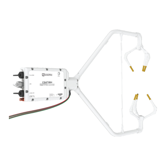
CSAT3BH Three-Dimensional Heated Sonic Anemometer Introduction The CSAT3BH is a heated version of the CSAT3B 3-D sonic anemometer with integrated electronics. This instrument measures sonic temperature and wind speed in three dimensions. The ultrasonic transducers, chassis, and strut can be heated to keep ice from accumulating on the instrument. -
Page 14: Initial Inspection
CM250 levelling mounting kit • USB data cable • Cables for the CSAT3BH are ordered separately but are specified at the time of order and are then also shipped with the CSAT3BH: CSAT3HCBL3-L • RS485 cable (either CSAT3HCBL1-L or CSAT3HCBL2) •... -
Page 15: Features
The CSAT3BH is a heated version of the CSAT3B. The measurement specifications of the CSAT3BH are the same as the CSAT3B. This sensor is designed to be used in cold environments that typically experience ice buildup on sensors. The CSAT3BH is designed to prevent ice from accumulating on the sensor in order to avoid prolonged periods of data loss. -
Page 16: Sensor Components
CSAT3BH Three-Dimensional Heated Sonic Anemometer Sensor Components The CSAT3BH consists of several components. Some components come standard with every CSAT3BH; others are considered accessories that must be ordered separately. Some common accessories such as cables are required to operate a CSAT3BH. -
Page 17: Cm250 Levelling Mounting Kit
USB port on the back of the CSAT3BH block as well as the USB port on the bottom of the CSAT3H heater controller box. The mini-B male connector is rated to Ingress Protection 68 (IP68) to exclude fine dust and water. -
Page 18: Optional Components
CSAT3BH in a protected position while providing space for additional components. If opting out of the sonic carrying case, the CSAT3BH will be shipped in a large cardboard box. The same set of foam inserts used in the sonic carrying case are used in the cardboard box to securely hold the CSAT3BH. -
Page 19: Power And Communications Cables
CSAT3BH Three-Dimensional Heated Sonic Anemometer 4.2.3.1 Power and Communications Cables Cables required for the CSAT3BH to be functional, must be ordered along with the CSAT3BH. Cables are required for both the anemometer itself and the CSAT3H controller box. The anemometer requires a communication cable that transfers the data to the data logger. -
Page 20: Options For Csat3Bcbl1 Power/Sdm Cable
CSAT3BH Three-Dimensional Heated Sonic Anemometer Power/SDM Cable (CSAT3BCBL1) To use SDM communications to collect data from a CSAT3BH with a data logger, the CSAT3BCBL1-L-PT or CSAT3BCBL1-L-MC should be ordered. FIGURE shows the two versions. This cable transmits both power and SDM communication signals. -
Page 21: Options For Cabling Cpi Or Rs-485 Communications
CSAT3H heater controller RS-485 RX Cable (CSAT3HCBL2) If the sonic anemometer is using a computer or a data acquisition system other than a Campbell Scientific data logger to collect data, then a CSAT3HCBL2 should be ordered. This cable is the connection between the CSAT3H heater controller box and a computer or other data acquisition system that is not a Campbell Scientific data logger. -
Page 22: Fw05 Thermocouple
4.2.3.5 Thermocouple Cover Backplate The CSAT3BH fine-wire thermocouple cover backplate attaches to the CSAT3BH block and is used to cover the back side of the thermocouple (TC) cover. NOTE The backplate is required for the CSAT3BH but not for other Campbell sonic anemometers. -
Page 23: Fw/Enc Thermocouple Enclosure
FW/ENC when not in use. It is also recommended to order, at a minimum, a set of four FW05 thermocouples for every CSAT3BH as the FW05 will break during normal wear and tear in the field. -
Page 24: Cpi/Rs-485 Splitter
The CPI/RS-485 splitter has three 8-pin M16 connectors. The splitter, shown in FIGURE 4-12, allows connection at the CPI/RS-485 port on the back of the CSAT3BH block to two CSAT3BCBL3 cables. The splitter is IP68 rated. It is used for daisy-chaining multiple CSAT3BHs in series that use CPI or RS-485 communications. -
Page 25: Hub-Sdm8
The HUB-SDM8 (shown in FIGURE 4-13) allows up to six SDM devices (typically, one data logger and multiple SDM sensors) to be connected in parallel. In the case of the CSAT3BH, up to five CSAT3BHs, or CSAT3BH daisy-chains using CSAT3BCBL1 cables, may be connected to the HUB- SDM8. -
Page 26: Sdm Cable Cable5Cbl-L
4.2.4.5 HUB-CPI The 8-channel RJ45 HUB-CPI allows up to eight CPI devices to be connected in parallel. In the case of the CSAT3BH, up to seven CSAT3BHs, or CSAT3BH daisy-chains using CSAT3BCBL3 cables, may be connected in parallel to the HUB-CPI. The remaining port may be used with a CAT5e or CAT6 Ethernet cable (see Section 4.2.4.4, SDM Cable CABLE5CBL-L... -
Page 27: Cat6 Ethernet Cable
CPI port on a data logger such as the CR6. FIGURE 4-15. CAT6 Ethernet cable Specifications The CSAT3BH measures wind speed and the speed of sound along the three non-orthogonal sonic axes. The wind speeds are then transformed into the orthogonal wind components u... -
Page 28: Measurements
CSAT3BH Three-Dimensional Heated Sonic Anemometer Measurements Operating Temperature Standard: –40 to 50 °C Wind Accuracy (–40 to 50 °C, wind speed < 30 m·s , azimuth angles between ± 170 °C) –1 Offset Error ± 8 cm·s –1 ± 8 cm·s –1... -
Page 29: Communications
CSAT3BH Three-Dimensional Heated Sonic Anemometer Communications SDM: Used for data logger-based data acquisition. Bit Period: 10 µs to 1 ms Cable Length: 7.6 m (25 ft) max @ 10 µs bit period 76 m (250 ft) max @ 1 ms bit period Address Range: 1 –... -
Page 30: Physical Description
CSAT3BH Three-Dimensional Heated Sonic Anemometer Physical Description 5.4.1 Sonic Anemometer Dimensions Overall: 63.1 cm (24.8 in) length 43.3 cm (17.0 in) height 12.3 cm (4.9 in) width Measurement Path: 10.0 cm (3.9 in) vertical 5.8 cm (2.3 in) horizontal Transducer Angle:... -
Page 31: Installation
The CSAT3BH includes the CSAT3BH sonic anemometer, CSAT3H heater controller box, and temp/RH sensor with six-gill radiation shield mounting hardware, and USB cables to connect to the CSAT3BH and CSAT3H heater controller box. All other cables are purchased separately so that they may be correctly selected for type of communication and sized to the requirements of the site setting. -
Page 32: Site Considerations
300-ft long, allowing the data logger to be up to 300 ft from the controller box. If the CSAT3BH is to be used in a marine environment, or in an environment where it is exposed to corrosive chemicals (for example, the sulfur-containing... -
Page 33: Connecting Csat3Bh Using Device Configuration Utility
Select the appropriate communication port and baud rate (refer to the left side of FIGURE 6-1). If this is the first time the computer has connected to a CSAT3BH and depending on the computer settings, the USB driver may need to be manually installed. -
Page 34: Csat3Bh Settings And Status Values In Device Configuration
CSAT3BH Three-Dimensional Heated Sonic Anemometer TABLE 6-1. CSAT3BH Settings and Status Values in Device Configuration Utility Setting or Status Subscreen Value Options Description Shows real-time measurements of U sonic temperature (T ), and the diagnostic word. If operating in Mode 0 (see Section 7.3,... - Page 35 CSAT3BH Three-Dimensional Heated Sonic Anemometer TABLE 6-1. CSAT3BH Settings and Status Values in Device Configuration Utility Setting or Status Subscreen Value Options Description 10 Hz Unprompted 20 Hz Identifies the rate at which to output Output Rate 50 Hz unprompted data...
-
Page 36: Setup The Data Logger And Csat3H Heater Controller
LoggerNet. NOTE A CR6 or CR1000X data logger is recommended with the CSAT3BH. For information on configuring another data logger with the CSAT3BH, please contact Campbell Scientific. From the LoggerNet toolbar, go to the Standard view of the setup screen by clicking Setup. -
Page 37: Mounting
(referred to generically as a CM20X crossarm). The following steps describe a general mounting procedure. The CSAT3H heater controller box must be mounted within 15 ft of the CSAT3BH. The temp/RH sensor used by the CSAT3H heater controller box has a 17 ft cable, and should be mounted at... -
Page 38: Mount The Csat3Bh
3/16-in hex socket head wrench. Refer to FIGURE 6-3. Attach the CSAT3BH to the levelling mount by inserting the bolt on the mount into the threaded hole on the bottom of the CSAT3BH block as shown in FIGURE 6-3. -
Page 39: Mount The Csat3H
6.4.2 Mount the CSAT3H The CSAT3H heater controller box must be mounted within 15 ft of the CSAT3BH sensor due to cable length limitations. Position the CSAT3H heater controller box such that it is within 15 ft of the sensor. -
Page 40: Mount The Temperature/Relative Humidity Probe
FIGURE 6-5. Mounting the temperature/relative humidity probe Orientation The three components of wind are defined by a right-handed orthogonal coordinate system. The CSAT3BH points into the negative x direction (see FIGURE 6-8). If the anemometer is pointing into the wind, it will report a positive u wind. -
Page 41: Right-Hand Coordinate System, Horizontal Wind Vector Angle Is 0 Degrees
CSAT3BH Three-Dimensional Heated Sonic Anemometer NOTE Remember to account for the magnetic declination at the site; see Appendix A, CSAT3BH Orientation , for details. If using an (p. A-1) app on a cellular phone, magnetic declination is most likely already taken into consideration. -
Page 42: Levelling
Finally, tighten the bolt with a 9/16-in wrench. If an application requires greater accuracy in inclination of the CSAT3BH, or if an application requires a measurement that shows if, and when, the inclination... -
Page 43: Installing Additional Fast-Response Sensors
TC cover backplate) can be mounted to the side of the anemometer block to measure temperature fluctuations. First, attach the TC cover backplate to the CSAT3BH with the screw that was included. Next, attach the female connector from the FWC-L to the side of the anemometer with the short screw (#2-56 x 0.437 inch) that was provided with... -
Page 44: Exploded View Of Fine-Wire Thermocouple (Tc) With Csat3Bh
CSAT3BH Three-Dimensional Heated Sonic Anemometer FWC-L TC Cover Backplate TC Cover FW05 FIGURE 6-9. Exploded view of fine-wire thermocouple (TC) with CSAT3BH FIGURE 6-10. CSAT3BH with fine-wire thermocouple mounted... -
Page 45: Other Gas Analyzers
Heater Controller enclosure, and CSAT3BH electronics should all be grounded to the same grounding rod. On the back of the CSAT3BH block there is a copper grounding lug (refer to FIGURE 6-11). Use a standard flat-head screwdriver to pinch an 8 AWG to 14 AWG wire between the lug and the lug screw. -
Page 46: Grounding Lug Of Csat3Bh
A minimum 14 AWG wire is recommended. CSAT3BH Grounding Lug FIGURE 6-11. Grounding lug of CSAT3BH If connecting multiple CSAT3BHs together either in a series or a NOTE star topology, each CSAT3BH must be separately grounded to either the mounting structure or a grounding rod. -
Page 47: Grounding Lug And Connectors On Bottom Of Csat3H Heater Controller Box
CSAT3BH Three-Dimensional Heated Sonic Anemometer CSAT3H Grounding Lug FIGURE 6-12. Grounding lug and connectors on bottom of CSAT3H heater controller box TABLE 6-2. Cable Wire Assignments CSAT3BH Cable Type Signal Description Pigtail Colour Power 9.5-32 VDC Ground Black SDM GND... -
Page 48: Controller Box Connections
Connect the cable from the Temp/RH sensor to the heater controller connection labeled Temp/RH. Connect the heater and chassis temp cables from the CSAT3BH to the Heaters and Chassis Temp connections on the heater controller. Connect the cable from the external 22-32 VDC power supply to the Power In connection. -
Page 49: Communications
Heaters that is coming out of the sonic to the connector on the controller box labeled Heaters. Communications If the CSAT3BH is going to be operated using SDM or CPI communications where the data logger triggers the measurement and the data is unfiltered (see Mode 0 in Section 7.3, Operating Modes ), then the CSAT3BH default (p. -
Page 50: Summary Of Communications Options For The Csat3Bh
CSAT3BH sensor, that sensor will report a Low Voltage diagnostic bit (see TABLE 7-6) and the Status light will flash red. To resolve this issue, power the CSAT3BH network using a higher voltage (up to 32 VDC) or install a capacitor at one of the current... -
Page 51: Sdm Communications
No other cables are required for SDM communications, as the CSAT3BCBL1 contains both power and SDM wiring. If only one CSAT3BH is being measured, the opposite end of the cable will have wire pigtails if connecting directly to the ports on a data logger. Refer to Section 6.9, Communications... -
Page 52: Wiring Diagram For Csat3Bh With Sdm Communications On
CSAT3BCBL1 SDM/Power cable from CSAT3B CSAT3HCBL1-L to CSAT3H controller boxes RS-485 TX/RX connectors FIGURE 6-14. Wiring to power and SDM ports on CR6 data logger TABLE 6-6. Wiring Diagram for CSAT3BH with SDM Communications on CR6 CR6 Data Logger Terminal Wire Colour 12 V (or other 9.5 to 32 VDC source) -
Page 53: Wiring Diagram For Csat3Bh With Sdm Communications On
Section 7.3, Operating Modes , for more details), the (p. 56) CSAT3BH Status light will flash red until a data logger is connected to the CSAT3BH and its program is running and sending measurement triggers. FIGURE 6-15. Lit status light on CSAT3BH block... -
Page 54: Multiple Csat3Bh Configurations
(p. 20) been assigned a unique SDM address. Connect a CSAT3BCBL1 to the Power/SDM port of the terminal CSAT3BH. The opposite end will have an M16 connector that mates with one of the split M16 connectors on the Power/SDM splitters. Next, screw the side of the splitter with only one M16 connector to the Power/SDM port of the second CSAT3BH. -
Page 55: Sdm Daisy Chain
CSAT3BH Three-Dimensional Heated Sonic Anemometer CSAT3BCBL1-L-MC Power/SDM Splitter CSAT3BCBL1-L-MC Power/SDM Splitter To power supply CSAT3BCBL1-L-PT CSAT3HCBL1-L to CSAT3H controller boxes RS-485 TX/RX connectors FIGURE 6-16. SDM daisy chain (CSAT3BH sensor arms and grounding cables not shown) -
Page 56: Cpi Communications
Next, connect a CSAT3BCBL3 to the CPI/RS-485 port in the same manner. If only one CSAT3BH is being measured, the opposite end of the power cable... - Page 57 CSAT3BH Three-Dimensional Heated Sonic Anemometer should have pigtail wires which may be wired to the 12 V and G terminals on a data logger or to a separate 12 to 32 VDC nominal power supply. The CPI cable should have the RJ-45 connector plugged into the CPI port of the data logger.
-
Page 58: Cpi Daisy Chain
CSAT3BH Three-Dimensional Heated Sonic Anemometer To 12 VDC power CSAT3BCBL1 SDM/Power cable from CSAT3BH CSAT3HCBL1-L to CSAT3BH controller box RS-485 TX/RX connector FIGURE 6-19. CPI connection to a CR6 data logger CPI Daisy-chain Topology For an application that requires CPI communication from multiple CSAT3Bs in series, or with a daisy-chain topology, first connect to each CSAT3B as described in Section 6.3, Settings... - Page 59 CSAT3BH Three-Dimensional Heated Sonic Anemometer of a data logger or to a separate 12 to 32 VDC nominal power supply (for convenience, it is possible to use a wiring bus such as the HUB-SDM8 to bring several power wires together and then extend a single cable such as the CABLEPCBL-L from the bus to the power supply).
- Page 60 CSAT3BH Three-Dimensional Heated Sonic Anemometer CSAT3BCBL2-L-MC Power/SDM Splitters CSAT3BCBL3-L-MC CSAT3BCBL2-L-MC CPI/RS-485 Splitter Power/SDM Splitter CSAT3BCBL3-L-MC CSAT3BCBL2-L-PT To power supply CPI/RS-485 Splitter CSAT3BCBL3-L-RJ To power supply FIGURE 6-20. CPI daisy chain (CSAT3BH sensor arms and grounding cables not shown)
- Page 61 CSAT3BH Three-Dimensional Heated Sonic Anemometer CSAT3BCBL2-L-PT CSAT3BCBL3-L-RJ HUB-CPI To power supply CAT6 Cable FIGURE 6-21. CPI star topology (CSAT3BH sensor arms and grounding cables not shown)
-
Page 62: Rs-485 Communications
Next, connect a CSAT3BCBL3 cable to the CPI/RS-485 port in the same manner. If only one CSAT3BH is being measured, the opposite end of the power cable should have pigtail wires, which may be connected to a 9.5 to 32 VDC power supply, and the RS-485 cable should have pigtail wires for wiring to a connector on a computer (see FIGURE 6-22). -
Page 63: Usb
FIGURE 6-22. RS-485 cable connections 6.10.3 USB If data collection from the anemometer is to be done by a computer using USB communications, first connect to the CSAT3BH as described in Section 6.3, Settings , to confirm the following three settings: (p. -
Page 64: Confirm Csat3Bh Factory Settings
CSAT3BH Three-Dimensional Heated Sonic Anemometer Connect the 5 m (16 ft) USB cable included with the CSAT3BH to the USB port in the same way. If only one CSAT3BH is being measured, the opposite end of the power cable should have pigtail wires, which may be connected to a 9.5 to 32 VDC power supply, and the USB cable should be connected to a USB... -
Page 65: Operation
The CSAT3BH is able to calculate the wind vector components along each sonic axis using the time difference between an outgoing and return sonic signal, along with the distance between sonic transducers. -
Page 66: Effects Of Crosswind On The Speed Of Sound
CSAT3BH. Liu et al. assume that the geometry of each individual three-dimensional anemometer is ideal when they derive the factors given in Table 1 of their publication. -
Page 67: Theory Of Heater Controller Operation
CSAT3BH Three-Dimensional Heated Sonic Anemometer The CSAT3BH embedded code improves the estimates of θ – and therefore the accuracy of the correction – by iteratively applying the preceding correction three times for each measurement of each sonic path. Since there continues to be some debate on the appropriateness of this and other shadow corrections in turbulent versus laminar flows, the default of this setting is Disabled. -
Page 68: Operating Modes
CSAT3BH operating modes. The following sections give more information on the measurement trigger, data filters, and data output as a guide to selecting the appropriate mode. Mode 0 is the default operating mode for the CSAT3BH and is recommended when fluxes are the primary interest. -
Page 69: Measurement Trigger
A measurement trigger is the actual command to initiate a sonic measurement and can be driven by either a data logger or the CSAT3BH internal timer. If the trigger is given by a data logger as in Mode 0, then no data filtering is done (bandwidth is wide open) since each trigger will initiate a single new measurement (single-measurement regime). -
Page 70: Csat3Bh Sonic Data Output
CSAT3BH OS versions 1.09 and newer. 7.3.3 CSAT3BH Sonic Data Output After a measurement is triggered and optionally run through a filter, it is stored in the CSAT3BH data buffer until it is output to either a data logger or a computer. - Page 71 (Mode 1) using CPI communications. In this case, the data logger will prompt the CSAT3BH for an output each time it executes the CSAT3B() CRBasic instruction in the program scan. When the data logger prompt is received by the CSAT3BH, it will output the most recent 100 Hz filtered sample in its buffer to the data logger.
- Page 72 In most situations, a computer computes the signature by reading in the ASCII data and extracting the last four ASCII characters, casting them as Long data type. The signature is then calculated on the data sent from the CSAT3BH, starting with u and ending with the counter.
-
Page 73: Operating Mode Recommendations
Mode 1, along a sample rate sufficient to capture the high- frequency variations that contribute to fluxes. Synchronization with Other Sensors As there is a delay between the CSAT3BH measurement and output to a data logger or computer (see TABLE 7-2), the CSAT3BH data will be slightly older... -
Page 74: Measurement Lags
CSAT3BH data. The lags shown for Modes 1 and 3, indicate the number of output scans that the analogue measurements should be delayed. -
Page 75: Data Logger Programming Using Sdm Or Cpi
7.5.1.1 CSAT3B() The CSAT3B() instruction is the primary instruction used to retrieve anemometer data from the CSAT3BH. This will set the operating mode of the anemometer and retrieve the wind, sonic temperature, and diagnostic information. The instruction requires four parameters which are further described in the following sections: •... -
Page 76: Csat3Bmonitor()
7.5.2 Diagnostic Word The fifth output from the CSAT3BH is the diagnostic word. The diagnostic word describes the status of the anemometer and is useful in filtering data. For example, when the anemometer is locking in on the ultrasonic signals after... -
Page 77: Diagnostic Word Flags
CSAT3BH. The data logger will display the diagnostic word as a base- 10 integer. Viewed in this manner, each of the 32 bits has a different magnitude as a decimal number. -
Page 78: Sdmtrigger()
7.5.3 SDMTrigger() The SDMTrigger() is an SDM Input/Output instruction that controls SDM devices that support the group trigger protocol, including the CSAT3BH. Up to 15 group-trigger devices can be connected to the SDM bus. All group-trigger devices are triggered for simultaneous measurements with the SDMTrigger(). - Page 79 This could result in a deep draining of a power supply. If such logic is desired, please work with Campbell Scientific to add a timeout into the code. TABLE 7-7. CSAT3H Heater Controller Outputs...
-
Page 80: Csat3H Heater Controller Outputs
CSAT3BH Three-Dimensional Heated Sonic Anemometer TABLE 7-7. CSAT3H Heater Controller Outputs Variable Name Units Description set_T_pt_arms_Avg °C Temperature that arms are set to heat to; NaN if no heating is needed Average ambient temperature measured by the temp/RH probe T_amb_ctrl °C... -
Page 81: Maintenance And Troubleshooting
CSAT3BH Three-Dimensional Heated Sonic Anemometer Maintenance and Troubleshooting General Maintenance With no moving parts, maintenance of the CSAT3BH is minimal and limited to the following: • Replacing the desiccant canister Monitoring diagnostics and measurement offsets to determine when • factory recalibration is needed Monitoring diagnostics to assure battery bank for both 12 and 24 VDC •... -
Page 82: Desiccant
Replacement top wicks and bottom wicks can be purchased from Campbell Scientific. A complete set of wicks for one CSAT3BH consists of three top wicks and three bottom wicks. - Page 83 CSAT3BMonitor() instruction in CRBasic Editor, or manually by connecting a CSAT3BH to a computer using the USB cable and then launching the Device Configuration Utility. Under the Settings Editor tab of the utility, there is secondary tab for Real-Time Data, where the internal humidity measurement will be displayed along with various other measurements.
-
Page 84: Calibration
Because it is difficult to do this in the field, wind offset data from the CSAT3BH should be collected in a field office or the lab. A zero- wind environment can be created with a kitchen waste bin liner. The following steps should be taken to test the CSAT3BH for wind offset. -
Page 85: Csat3Bh Real-Time Data With 1 Sec Update And U
CSAT3BH Three-Dimensional Heated Sonic Anemometer drafts to pass by the CSAT3BH. Ensure that the liner does not obstruct any of the three CSAT3BH sonic paths. Connect the CSAT3BH power and communications cable to the data logger referring to Section 5.2, Communications . -
Page 86: Troubleshooting
FIGURE 8-4. CSAT3BH real-time data with 1 sec update and u wind component graphed Graph 1 minute of wind data from the CSAT3BH while it is in the zero wind environment. The wind offset should be less than ± 8 cm·s –1 (0.08 m·s... -
Page 87: Troubleshooting Csat3H Heater Controller Box Issues
If the problems are still unresolved, contact Campbell Scientific. If possible, be prepared to send a file of CSAT3BH output data, including the diagnostic word, to Campbell Scientific. If it is determined that the unit must be returned to the factory for recalibration and/or repair an RMA will be required (see Section 8.6, Returning the CSAT3BH... -
Page 88: Returning The Csat3Bh
Campbell Scientific. When preparing the CSAT3BH for shipment, be sure to package it in the same foam that it was sent in. If the foam cannot be found, new foam should be ordered from... -
Page 89: References
CSAT3BH Three-Dimensional Heated Sonic Anemometer References Liu, H., Peters, G. and Foken, T.: 2001, “New Equations for Sonic Temperature Variance and Buoyancy Heat Flux with an Omnidirectional Sonic Anemometer”, Boundary-Layer Meteorol., 100, 459 – 468. Kaimal, J.C.: 1979, “Sonic anemometer measurement of atmospheric turbulence”, Proceeding of the Dynamic Flow Conference, Skovlunde. -
Page 91: Wind Direction Sensor Orientation
Appendix A. Wind Direction Sensor Orientation A.1 Determining True North and Sensor Orientation Orientation of the wind direction sensor is done after the datalogger has been programmed, and the location of True North has been determined. True North is usually found by reading a magnetic compass and applying the correction for magnetic declination;... -
Page 92: Magnetic Declination At 2012.5
Appendix A. Wind Direction Sensor Orientation Figure A-1. Magnetic Declination at 2012.5 (degrees relative to true north, positive is east) Figure A-2. Declination Angles East of True North Are Subtracted From 0 to Get True North... -
Page 93: Declination Angles West Of True North Are Added To 0 To Get
Appendix A. Wind Direction Sensor Orientation Figure A-3. Declination Angles West of True North Are Added to 0 to Get True North... - Page 94 Appendix A. Wind Direction Sensor Orientation This is a blank page.
-
Page 95: Csat3Bh Measurement Theory
Theory B.1 Theory of Operation B.1.1 Wind Speed Each axis of the CSAT3BH pulses two ultrasonic signals in opposite directions. The time of flight of the first signal (out) is given by: (B-1) and the time of flight of the second signal (back) is given by:... -
Page 96: Temperature
The sonically determined speed of sound is given in Eq. (B-5) and was found from the sum of the inverses of Eq. (B-1) and (B-2). The CSAT3BH corrects online for the effect of wind blowing perpendicular to the sonic path. No additional off-line corrections are required as suggested by Liu et al., 2001. - Page 97 Appendix B. CSAT3BH Measurement Theory and C = specific heat of dry air, respectively (Fleagle and Businger, 1980) Substitute Eq. (B-7a) and (B-7b) into (B-6) and ignore the higher order terms. This yields 1 0 51 γ γ d d s...
- Page 98 Campbell Scientific regional offices Australia France Thailand Location: Garbutt, QLD Australia Location: Vincennes, France Location: Bangkok, Thailand Phone: 61.7.4401.7700 Phone: 0033.0.1.56.45.15.20 Phone: 66.2.719.3399 Email: info@campbellsci.com.au Email: info@campbellsci.fr Email: info@campbellsci.asia Website: www.campbellsci.com.au Website: www.campbellsci.fr Website: www.campbellsci.asia Brazil Germany Location: São Paulo, SP Brazil...
Need help?
Do you have a question about the CSAT3BH and is the answer not in the manual?
Questions and answers