
Subscribe to Our Youtube Channel
Related Manuals for Campbell CSAT3BH


Summary of Contents for Campbell CSAT3BH
- Page 1 Product Manual Revision: 01/2022 Copyright © 2020 – 2022 Campbell Scientific, Inc.
-
Page 2: Table Of Contents
Table of contents 1. Introduction 2. Precautions 3. Initial inspection 4. Overview 4.1 Features 4.2 Sensor components 4.2.1 Standard components 4.2.1.1 CSAT3H heater controller box 4.2.1.2 Temperature/relative humidity sensor and shield 4.2.1.3 CM250 leveling mounting kit 4.2.1.4 USB data cable 4.2.2 Optional components 4.2.2.1 Sonic environment option 4.2.2.2 Sonic carrying case... - Page 3 6.10 Multiple CSAT3BH configurations 6.10.1 CPI communications 6.10.2 RS-485 communications 6.10.3 USB 6.11 Confirm CSAT3BH factory settings 7. Operation 7.1 Theory of operation for wind and sonic temperature measurements 7.1.1 Algorithm Version 5 7.1.2 Effects of crosswind on the speed of sound 7.1.3 Sonic transducer shadow correction...
- Page 4 8.4.1 Test for wind offset 8.5 Troubleshooting 8.5.1 Troubleshooting CSAT3H heater controller box issues 8.5.2 Sending an OS to the CSAT3H heater controller box 8.5.3 Sending an OS to the CSAT3BH 8.6 Returning the CSAT3BH 9. References Appendix A. CSAT3BH orientation A.1 Determining true north and sensor orientation...
- Page 5 B.2 References Table of contents - iv...
-
Page 6: Introduction
9.5 to 32 VDC into the power connector on the CSAT3BH electronics. The CSAT3BH head should be handled by holding the block at the back of the sensor. Handling it by the arms or transducers could cause geometric deformation, which degrades the measurements. -
Page 7: Initial Inspection
3. Initial inspection Upon receipt of the CSAT3BH, inspect the packaging and contents for damage. File any damage claims with the shipping company. Contact Campbell Scientific to facilitate repair or replacement. Immediately check package contents against shipping documentation. Thoroughly check all packaging material for product that may be trapped inside. -
Page 8: Overview
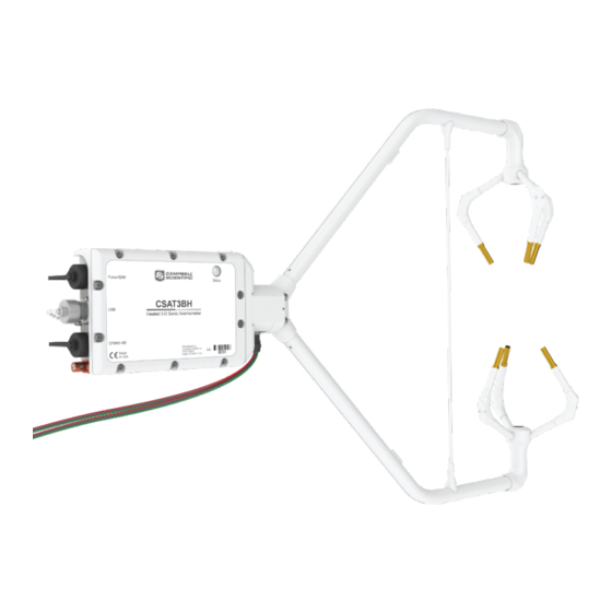
Cables for the CSAT3BH, although not included in the standard package, are specified at the time of order and are shipped with the CSAT3BH: CSAT3HCBL3-L RS-485 cable (either CSAT3HCBL1-L or CSAT3HCBL2) Either CSAT3BCBL1-L or CSAT3BCBL2-L and CSAT3BCBL3-L 4. Overview The CSAT3BH is an ultrasonic anemometer for measuring sonic temperature and wind speed in three dimensions. -
Page 9: Features
Streamlined heater integration to preserve sonic aerodynamics and ensure proper operation 4.2 Sensor components The CSAT3BH consists of several components. Some components come standard with every CSAT3BH; others are accessories that must be ordered separately. Some common accessories, such as cables, are required to operate a CSAT3BH. -
Page 10: Standard Components
4.2.1 Standard components Standard components are items that are included or shipped with the CSAT3BH. The following sections describe these items. 4.2.1.1 CSAT3H heater controller box The CSAT3H heater controller box collects temperature and relative humidity data from the temp/RH probe (see Temperature/relative humidity sensor and shield (p. -
Page 11: Cm250 Leveling Mounting Kit
USB port on either the back of the CSAT3BH block or the bottom of the CSAT3H heater controller box. The mini-B pin connector is rated to Ingress Protection 68 (IP68) to exclude fine dust and water. -
Page 12: Optional Components
Configuration Utility allows the user to view or set settings, send a new operating system to the CSAT3BH, or view real-time measurements. It is also possible to use this cable to collect data with a computer in unprompted USB mode. -
Page 13: Common Accessories
4.2.3.1 Power and communications cables Cables required for the CSAT3BH to function must be ordered with the CSAT3BH. Cables are required for both the anemometer itself and the CSAT3H controller box. The anemometer requires a communication cable that transfers the data to the data logger. - Page 14 To collect data through another means (such as CPI, RS-485, or USB), the CSAT3BCBL1 Power/SDM cable may still be used to provide power to the CSAT3BH, in which case the SDM wires should be left unwired to any ports on the data logger.
- Page 15 1 and 300 ft. CSAT3H heater controller RS-485 RX cable (CSAT3HCBL2) If the sonic anemometer is using a computer or a data acquisition system other than a Campbell Scientific data logger to collect data from the CSAT3H heater controller box, then a CSAT3HCBL2...
-
Page 16: Fw05 Thermocouple
The thermocouple measures atmospheric temperature fluctuations and may be used with the CSAT3BH to directly calculate sensible heat flux. Larger size fine-wire thermocouples, such as the FW1 and FW3, which are more robust but have slower response times, may also be used with the CSAT3BH. -
Page 17: Thermocouple Cover
FW/ENC when not in use. Ordering at least a set of four FW05 thermocouples for every CSAT3BH is recommended, as the FW05 will break during normal wear and tear in the field. FIGURE 4-9. FW/ENC for storing fragile thermocouples 4.2.4 Other accessories... -
Page 18: Power/Sdm Splitter
FIGURE 4-10 (p. 13), has three 6-pin M16 connectors. This splitter allows for connection at the Power/SDM port on the back of the CSAT3BH block to two CSAT3BCBL1 or CSAT3BCBL2 cables. The splitter is IP68 rated, meaning it is dustproof and watertight. -
Page 19: Cpi/Rs-485 Splitter
(p. 14), has three 8-pin M16 connectors. This splitter allows for connection at the CPI/RS-485 port on the back of the CSAT3BH block to two CSAT3BCBL3 cables. The splitter is IP68 rated. It is used for daisy-chaining multiple CSAT3BHs in series that use CPI or RS-485 communications. -
Page 20: Hub-Sdm8
(p. 16)) allows up to six SDM devices (typically, one data logger and multiple SDM sensors) to be connected in parallel. In the case of the CSAT3BH, up to five CSAT3BHs, or CSAT3BH daisy chains using CSAT3BCBL1 cables, may be connected to the HUB-SDM8. -
Page 21: Sdm Cable Cable5Cbl-L
The 8-channel RJ45 HUB-CPI allows up to eight CPI devices to be connected in parallel. Up to seven CSAT3BHs, or CSAT3BH daisy chains using CSAT3BCBL3 cables, may be connected in parallel to the HUB-CPI. The remaining port may be used with a CAT5e or CAT6 Ethernet cable... -
Page 22: Cat6 Ethernet Cable
The vector component of the wind that is normal to each sonic axis (such as a crosswind) leads to a measurement error that is corrected online by the CSAT3BH before the wind speed is CSAT3BH Three-Dimensional Heated Sonic Anemometer... -
Page 23: Measurements
(such as computer data collection), the output is prompted by the CSAT3BH itself. The default operating mode of the CSAT3BH is to make measurements when triggered by a data logger (SDM or CPI), which does not apply any low-pass (high-cut) filtering. -
Page 24: Communications
SDM: Used for data logger-based data acquisition. Bit period: 10 µs to 1 ms Cable length: 7.6 m (25 ft) max @ 10 µs bit period 76 m (250 ft) max @ 1 ms bit period Address range: 1 to 14 CSAT3BH Three-Dimensional Heated Sonic Anemometer... -
Page 25: Power Requirements
USB: Used for anemometer configuration or computer-based data acquisition. Connection speed: USB 2.0 full speed 12 Mbps Cable length: 5 m max For additional details, refer to Campbell Scientific whitepaper “Designing Physical Network Layouts for the CPI Bus” 5.3 Power requirements Anemometer voltage requirement: 9.5 to 32 VDC... -
Page 26: Physical Description
9.1 kg (20.0 lb) Dimensions: 91 x 51 x 41 cm (36 x 20 x 16 in) Carrying case option Weight: 16.3 (36.0 lb) Dimensions: 81 x 66 x 43 cm (32 x 26 x 17 in) CSAT3BH Three-Dimensional Heated Sonic Anemometer... -
Page 27: Csat3H Heater Controller Box Dimensions
21.8 cm (8.6 in) width Weight: 1.9 kg (4.2 lb) Shipping box Weight (with controller): 3.3 kg (7.3 lb) Dimensions: 41 x 41 x 20 cm (16 x 16 x 8 in) FIGURE 5-1. Dimensions of CSAT3BH CSAT3BH Three-Dimensional Heated Sonic Anemometer... -
Page 28: Installation
300 ft from the controller box. If the CSAT3BH is to be used in a marine environment or in an environment where it is exposed to corrosive chemicals (for example, the sulfur-containing compounds in viticulture), attempt to mount the CSAT3BH in a way that reduces exposure of the sonic transducers to saltwater or corrosive chemicals. -
Page 29: Settings
CSAT3BH, which is covered in the following sections. 6.3 Settings Prior to installation, the CSAT3BH settings should be verified in a lab setting to make sure all parts are accounted for and the system is functioning properly. 6.3.1 Verify CSAT3BH settings Verify the CSAT3BH settings in a laboratory through the following steps: 1. - Page 30 FIGURE 6-1. Connecting CSAT3BH using Device Configuration Utility 7. Once connected, the main screen will have a section with tabs to view the following four subscreens: Real-Time Data, Communication Settings, Measurement Settings, and Instrument ID. Table 6-1 (p. 26) describes each of the settings or status values in these subscreens.
- Page 31 Table 6-1: CSAT3BH settings and status values in Device Configuration Utility Setting or status Subscreen Options Description value Shows real-time measurements of u , sonic temperature (T ), and the diagnostic word. If operating in Mode 0 (see Operating modes (p.
- Page 32 Table 6-1: CSAT3BH settings and status values in Device Configuration Utility Setting or status Subscreen Options Description value 1 through 14 SDM Address Unique address for SDM device 1 through 120 CPI Address Unique address for CPI device Disable Both...
- Page 33 Table 6-1: CSAT3BH settings and status values in Device Configuration Utility Setting or status Subscreen Options Description value Mode 0: Data logger triggered | No filter | Data logger prompted output Mode 1: Self triggered | Filtered | Data logger Identifies the source of the...
-
Page 34: Set Up The Data Logger And Csat3H Heater Controller
LoggerNet. NOTE: A CR6 or CR1000X data logger is recommended with the CSAT3BH. For information on configuring another data logger with the CSAT3BH, please contact Campbell Scientific. 1. From the LoggerNet toolbar, go to the Standard view of the setup screen by clicking Setup. - Page 35 8. Once everything is entered correctly, click Apply. 9. If using IP, then follow the same steps and enter the IP address of the data logger. CSAT3BH Three-Dimensional Heated Sonic Anemometer...
-
Page 36: Mounting
The CSAT3BH and CSAT3H controller box is supplied with mounting hardware to attach it to the end of a horizontal pipe with an outer diameter of 3.33 cm (1.31 in), such as the Campbell Scientific CM202, CM204, or CM206 crossarm (referred to generically as a CM20X crossarm). The following steps describe a general mounting procedure. - Page 37 Refer to FIGURE 6-3 (p. 33). 4. Attach the CSAT3BH to the leveling mount by inserting the bolt on the mount into the threaded hole on the bottom of the CSAT3BH block as shown in FIGURE 6-3 (p. 33). The orientation of the CSAT3BH should be level and pointing in the direction of the prevailing wind.
-
Page 38: Mount Csat3H
FIGURE 6-3. CSAT3BH mounting 6.4.2 Mount CSAT3H The CSAT3H heater controller box must be mounted within 15 ft of the CSAT3BH sensor due to cable length limitations. 1. Position the CSAT3H heater controller box such that it is within 15 ft of the sensor. -
Page 39: Mount The Temperature/Relative Humidity Probe
FIGURE 6-5. Mounting the temperature/relative humidity probe 6.5 Orientation The three components of wind are defined by a right-handed orthogonal coordinate system. The CSAT3BH points into the negative x direction (see FIGURE 6-8 (p. 37)). If the anemometer is pointing into the wind, it will report a positive u wind. - Page 40 Remember to account for the magnetic declination at the site; see CSAT3BH orientation 92) for details. If using an app on a cellular phone, magnetic declination is most likely already taken into consideration. FIGURE 6-6. Right-hand coordinate system, horizontal wind vector angle is 0 degrees CSAT3BH Three-Dimensional Heated Sonic Anemometer...
-
Page 41: Leveling
Adjust the anemometer head so that the bubble within the level on top of the CSAT3BH block is in the bullseye. Firmly grasp the sonic anemometer block, loosen the bolt underneath the block, and adjust the head accordingly. - Page 42 CSAT3BH wind measurements. The outputs of the CSAT3BH integrated inclinometer can be viewed by connecting the USB data cable to the CSAT3BH and a computer running Campbell Scientific Device Configuration Utility. It can also be output using the CRBasic instruction CSAT3BMonitor().
-
Page 43: Installing Additional Fast-Response Sensors
First, attach the TC cover backplate to the CSAT3BH with the screw that was included. Next, attach the socket connector from the FWC-L to the side of the anemometer with the short screw (#2-56 x 0.437 in) that was provided with the white thermocouple cover. -
Page 44: Other Gas Analyzers
FIGURE 6-10. CSAT3BH with fine-wire thermocouple mounted 6.7.2 Other gas analyzers If a fast-response gas analyzer is being used with the CSAT3BH, care should be taken to mount the analyzer (open-path) or the analyzer intake (closed-path) as close as possible to the sonic sampling volume in order to obtain good spatial and temporal synchronicity between vertical wind and gas concentration fluctuations while also retaining adequate spatial separation. - Page 45 A 5-ft copper-clad grounding rod ships with Campbell Scientific tripods, or it can be purchased separately. The CSAT3BH has three watertight circular ports or connectors at the rear of the block. These are labeled Power/SDM, USB, and CPI/RS-485 as shown inFIGURE 6-11 (p.
- Page 46 If connecting multiple CSAT3BHs together either in a daisy chain series or star topology, each CSAT3BH must be separately grounded to either the mounting structure or a grounding rod. FIGURE 6-12. Grounding lug and connectors on bottom of CSAT3H heater controller box...
-
Page 47: Controller Box Connections
Power and communications cables (p. 8) for information about ordering cables.) 6.8.2 Controller box connections There are seven connectors on the CSAT3H heater controller box: RS-485 TX/RX Power In (22 to 32 VDC) RS-485 RX CSAT3BH Three-Dimensional Heated Sonic Anemometer... -
Page 48: Csat3H Heater Controller Connections
1. Connect the cable from the temp/RH probe to the heater controller connection labeled Temp/RH. 2. Connect the heater and chassis temp cables from the CSAT3BH to the Heaters and Chassis Temp connections on the heater controller. 3. Connect the cable from the external 22 to 32 VDC power supply to the Power In connection. -
Page 49: Communications
Finally, connect the other cable coming out of the sonic anemometer labeled Heaters to the connector on the controller box labeled Heaters. 6.9 Communications If the CSAT3BH is going to be operated using SDM or CPI communications where the data logger triggers the measurement and the data is unfiltered (see Mode 0 in Operating modes (p. - Page 50 Worse with other sensors Noisy environments Best Better Contact Campbell Scientific for instructions on how to configure a CR3000 NOTE: CPI communication is preferred over SDM communication when using a CR6 or CR1000X data logger. See Table 6-5 (p. 45) to examine the suitability of communications type based on various parameters for other combinations.
-
Page 51: Sdm Communications
SDM communications, as the CSAT3BCBL1 contains both power and SDM wiring. If only one CSAT3BH is being measured, the opposite end of the cable will have wire pigtails to connect directly to the ports on a data logger. Refer to Communications (p. - Page 52 FIGURE 6-13. Power/SDM connections FIGURE 6-14. Wiring to power and SDM ports on CR6 data logger CSAT3BH Three-Dimensional Heated Sonic Anemometer...
- Page 53 2. Verify that measurements are being made by ensuring the green Status light (FIGURE 6-15 (p. 49)) on the CSAT3BH block is blinking, indicating that measurements are being made and recorded in the data logger without diagnostic error conditions. CSAT3BH Three-Dimensional Heated Sonic Anemometer...
-
Page 54: Multiple Csat3Bh Configurations
Operating modes (p. 65) for more details), the CSAT3BH Status light will flash red until a data logger is connected to the CSAT3BH and its program is running and sending measurement triggers. FIGURE 6-15. Lit status light on CSAT3BH block 6.10 Multiple CSAT3BH configurations... - Page 55 If several CSAT3BHs using SDM communications are being connected in parallel or with a star topology, connect a CSAT3BCBL1 cable to the Power/SDM port of each CSAT3BH, and connect the other wires on the pigtail end of the cables to a HUB-SDM8 bus (see HUB-SDM8 (p.
- Page 56 FIGURE 6-16. SDM daisy chain (CSAT3BH sensor arms and grounding cables not shown) CSAT3BH Three-Dimensional Heated Sonic Anemometer...
-
Page 57: Cpi Communications
FIGURE 6-17. SDM star topology (CSAT3BH sensor arms and grounding cables not shown) 6.10.1 CPI communications If data collection from the anemometer is to be done by a data logger using CPI communications, then connect a CSAT3BCBL2 to the Power/SDM port by screwing the M16 connector into the port until tight. - Page 58 Next, connect a CSAT3BCBL3 to the CPI/RS-485 port in the same manner. If only one CSAT3BH is being measured, the opposite end of the power cable should have pigtail wires that may be wired to the 12 V and G terminals on a data logger or to a separate 12 to 32 VDC nominal power...
- Page 59 Refer to FIGURE 6-20 (p. 56) for the described connections. CSAT3BH Three-Dimensional Heated Sonic Anemometer...
- Page 60 Refer to FIGURE 6-21 (p. 57) for these connections. NOTE: The sockets or ports on the HUB-CPI are all the same. Any socket may be used to connect to the data logger or to other CSAT3Bs. CSAT3BH Three-Dimensional Heated Sonic Anemometer...
- Page 61 FIGURE 6-20. CPI daisy chain (CSAT3BH sensor arms and grounding cables not shown) CSAT3BH Three-Dimensional Heated Sonic Anemometer...
- Page 62 FIGURE 6-21. CPI star topology (CSAT3BH sensor arms and grounding cables not shown) CSAT3BH Three-Dimensional Heated Sonic Anemometer...
-
Page 63: Communications
Next, connect a CSAT3BCBL3 cable to the CPI/RS-485 port in the same manner. If only one CSAT3BH is being measured, the opposite end of the power cable should have pigtail wires, which may be connected to a 9.5 to 32 VDC power supply, and the RS-485 cable should have... -
Page 64: Usb
FIGURE 6-22. RS-485 cable connections 6.10.3 USB If data collection from the anemometer is to be done by a computer using USB communications, first connect to the CSAT3BH as described in Settings (p. 24) to confirm the following three settings:... -
Page 65: Confirm Csat3Bh Factory Settings
Connect the 5 m (16 ft) USB cable included with the CSAT3BH to the USB port in the same way. If only one CSAT3BH is being measured, the opposite end of the power cable should have pigtail wires, which may be connected to a 9.5 to 32 VDC power supply, and the USB cable should be... -
Page 66: Operation
The time of flight of a sonic signal between a pair of transducers is directly related to the wind vector component that is parallel to the sonic axis. The CSAT3BH is able to calculate the wind vector components along each sonic axis using the time difference between an outgoing and return sonic signal, along with the distance between sonic transducers. -
Page 67: Algorithm Version
Each time a significant change has been made to these algorithms, a new version number has been issued. The CSAT3BH uses algorithm Version 5. Version 5 maintains many of the advantages of signal recognition and diagnostic sensitivity that were made possible by Version 3, while also adding the advantages of performance during precipitation events made possible by Version 4. -
Page 68: Sonic Transducer Shadow Correction
FIGURE 7-1 (p. 64)) The CSAT3BH embedded code improves the estimates of θ — and therefore the accuracy of the correction — by iteratively applying the preceding correction three times for each measurement of each sonic path. Since debate continues on the appropriateness of this and other shadow corrections in turbulent versus laminar flows, the default of this setting is Disabled. -
Page 69: Theory Of Heater Controller Operation
If, within 60 seconds, the average number of diagnostic flags coming from the CSAT3BH is greater than 25 percent, the controller will go into the second mode. In the second mode, the heater voltage will increase every 15 minutes until the blockage is clear. Once the... -
Page 70: Operating Modes
CSAT3BH operating modes. The following sections give more information on the measurement trigger, data filters, and data output as a guide to selecting the appropriate mode. Mode 0 is the default operating mode for the CSAT3BH and is recommended when fluxes are the primary interest. -
Page 71: Measurement Trigger
A measurement trigger is the actual command to initiate a sonic measurement and can be driven by either a data logger or the CSAT3BH internal timer. If the trigger is given by a data logger as in Mode 0, then no data filtering is done (bandwidth is wide open) since each trigger will initiate a single new measurement (single-measurement regime). -
Page 72: Data Filter
The optional data filter (Modes 1 and 3) takes the 100 Hz sample points that were self-triggered by the CSAT3BH and runs them through a low-pass (high-cut) filter, resulting in a new filtered output at the same 100 Hz rate. The degree to which the data is filtered is determined by the user-selected filter bandwidth. -
Page 73: Csat3Bh Sonic Data Output
CSAT3BH OS versions 1.09 and newer. 7.3.3 CSAT3BH sonic data output After a measurement is triggered and optionally run through a filter, it is stored in the CSAT3BH data buffer until it is output to either a data logger or a computer. - Page 74 Modes 2 and 3 If the CSAT3BH measurements are to be self-triggered and output to a computer, as in Modes 2 and 3, an unprompted output operating mode should be selected. Available output rates for the CSAT3BH are 10, 20, 50, or 100 Hz. In unprompted mode, the CSAT3BH will downsample or decimate the 100 Hz buffer data (unfiltered or filtered, depending on whether the user has...
- Page 75 Table 7-3 (p. 71). Even after accounting for the sample delay, a synchronicity error between the computer and the CSAT3BH may still exist, since they each have their own clocks. Table 7-3 (p. 71) shows the possible synchronicity errors for each output rate.
-
Page 76: Operating Mode Recommendations
Due to the advantages in making synchronous measurements, Campbell Scientific recommends using a data logger that supports SDM or CPI communications to collect data from the CSAT3BH. If flux measurements are the primary interest, Campbell Scientific further recommends that the CSAT3BH be operated in Mode 0 where the data logger triggers the measurements, no filters are applied, and the data is collected by the data logger. - Page 77 For example, in Mode 1 where data is being filtered and then output is prompted by a data logger, if the data logger has a 10 Hz scan rate and the CSAT3BH has been set to use a 5 Hz bandwidth filter, the analog measurements should be delayed by eight data logger scans (eight 100 ms/scan = 800 ms).
-
Page 78: Data Logger Programming Using Sdm Or Cpi
CSAT3B() instruction is the primary instruction used to retrieve anemometer data from the CSAT3BH. This will set the operating mode of the anemometer and retrieve the wind, sonic temperature, and diagnostic information. The instruction requires four parameters that are further described in the following sections:... - Page 79 Destination This variable will store the values returned by the anemometer. The destination variable must be declared as a float (default) with at least five elements. The CSAT3BH returns the following data in response to a measurement trigger: — x-axis wind speed in meters per second (m·s —...
-
Page 80: Csat3Bmonitor()
Destination This variable will store the values returned by the anemometer. The destination variable must be declared as a float (default) with at least four elements. The CSAT3BH returns the following data in response to this instruction: Electronics temperature in degrees Celsius (°C) Electronics relative humidity as a percentage (%) Inclinometer pitch in degrees (°) -
Page 81: Diagnostic Word
The diagnostic word is formatted as a simple 32-bit binary word. Each bit in the diagnostic word represents a different warning flag related to the operation of the CSAT3BH. The data logger will display the diagnostic word as a base-10 integer. Viewed in this manner, each of the 32 bits has a different magnitude as a decimal number. -
Page 82: Sdmtrigger()
SDMTrigger() is an SDM Input/Output instruction that controls SDM devices that support the group trigger protocol, including the CSAT3BH. Up to 15 group-trigger devices can be connected to the SDM bus. All group-trigger devices are triggered for simultaneous measurements with the SDMTrigger(). The data from each device is retrieved with the appropriate device-specific instruction. -
Page 83: Programming
7.7 Data logger and CSAT3H heater controller box programs The CSAT3BH uses a smart heating algorithm to both maintain and clear obstructions from the sonic path. This requires the Campbell Scientific data logger program to contain the proper section of code for control. - Page 84 Both of these conditions will appear as a signal blockage. This could result in a deep draining of a power supply. If such logic is desired, please work with Campbell Scientific to add a timeout into the code.
- Page 85 Average ambient relative humidity measured by the RH_amb_ctrl temp/RH probe connected to the CSAT3H heater controller Average ambient dew point temperature determined by T_DP_amb_ctrl °C the temp/RH probe connected to the CSAT3H heater controller CSAT3BH Three-Dimensional Heated Sonic Anemometer...
- Page 86 Maximum consecutive seconds the transducers were secs_blocked_Max unable to establish a signal Maximum millivolt signal CSAT3H heater controller used mV_real_trnsds_Max to determine how much heat to apply to the transducers CSAT3BH Three-Dimensional Heated Sonic Anemometer...
-
Page 87: Maintenance And Troubleshooting
8. Maintenance and troubleshooting 8.1 General maintenance With no moving parts, maintenance of the CSAT3BH is minimal and limited to the following: Replacing the desiccant canister Monitoring diagnostics and measurement offsets to determine when factory recalibration is needed Monitoring diagnostics to assure battery bank for both 12 and 24 VDC power sources have... -
Page 88: Sonic Wicks
CAUTION: The cover plate to the CSAT3BH electronics should only be removed by qualified technicians at the factory. When covered, the electronics are well protected against transient voltages during handling and operation. Once uncovered, however, they are highly sensitive to electrostatic discharge. - Page 89 Replacement top wicks and bottom wicks can be purchased from Campbell Scientific. A complete set of wicks for one sonic anemometer consists of three top wicks and three bottom wicks.
-
Page 90: Desiccant
The CSAT3BH has a cavity to hold a replaceable desiccant canister that removes water from the air (see FIGURE 8-3 (p. -
Page 91: Calibration
Testing wind offset on a CSAT3BH requires creating an environment where wind is absent. Because it is difficult to do this in the field, wind offset data from the CSAT3BH should be collected in a field office or the lab. A zero-wind environment can be created with a kitchen waste bin liner. - Page 92 CSAT3BH head on its side or balance it on the transducers, as this will affect its measurements. 2. Cover the CSAT3BH head with a medium (13-gallon) kitchen waste bin liner. Close the opening of the liner by folding, taping, or tying, to prevent air from moving in and out of the liner.
-
Page 93: Troubleshooting
FIGURE 8-5. CSAT3BH real-time data with 1 sec update and u wind component graphed Graph 1 minute of wind data from the CSAT3BH while it is in the zero-wind environment. The –1 –1 –1 wind offset should be less than ±8 cm·s (0.08 m·s... -
Page 94: Troubleshooting Csat3H Heater Controller Box Issues
1. Perform a visual inspection of the CSAT3BH. Make sure it is clear from anything that might obstruct the sonic signal. Check for signs that the geometry of the arms has changed in any way, possibly from an impact from another object. -
Page 95: Sending An Os To The Csat3Bh
Settings (p. 24). 3. After connecting to the CSAT3BH, click the Send OS tab at the top of the Device Configuration Utility main screen. Click the Start button at the bottom of the page, select the .obj file that you downloaded from the Campbell website, and click Open. The OS will then be sent, followed by a confirmation message that it was loaded properly. -
Page 96: References
RMA number. If additional help is needed, please contact Campbell Scientific. When preparing the CSAT3BH for shipment, be sure to package it in the same foam in which it was sent. If the foam cannot be found, new foam should be ordered from Campbell Scientific before returning the unit. -
Page 97: Appendix A. Csat3Bh Orientation
FIGURE A-3 (p. 93). Note that when a negative number is subtracted from a positive number, the resulting arithmetic operation is addition. FIGURE A-1. Magnetic declination for the contiguous United States (2015) CSAT3BH Three-Dimensional Heated Sonic Anemometer... -
Page 98: Online Magnetic Declination Calculator
The magnetic declination web calculator published by the NOAA Geophysical Data Center is available at the following URL: https://www.ngdc.noaa.gov/geomag-web/#declination . Enter the latitude, longitude, date, and the format you wish to view the data. Once entered, click Calculate to determine the declination (FIGURE A-4 (p. 94)). CSAT3BH Three-Dimensional Heated Sonic Anemometer... - Page 99 The declination for Logan, UT, USA is 11.47° E. Therefore, true north is 360° – 11.47° = 348.53°. So when looking at a compass at this location, true north is located at 348.53°, not 360°. Declination results are typically accurate to 30 minutes of arc, but environmental factors can cause magnetic field disturbances. CSAT3BH Three-Dimensional Heated Sonic Anemometer...
-
Page 100: Appendix B. Csat3Bh Measurement Theory
B.1 Theory of operation B.1.1 Wind speed Each axis of the CSAT3BH pulses two ultrasonic signals in opposite directions. The time of flight of the first signal (out) is given by: Eq. 1 and the time of flight of the second signal (back) is given by: Eq. -
Page 101: Temperature
, and u ) with the following: Eq. 4 where: A = a 3 x 3 coordinate transformation matrix that is unique for each CSAT3BH and is stored in ROM memory B.1.2 Temperature The sonically determined speed of sound is given in Eq. - Page 102 The sonic virtual temperature, in degrees Celsius, is given by Eq. 10 = 1.4 and R = 287.04 JK Eq. 10 B.2 References Fleagle, R.G. and J.A. Businger. 1980. An Introduction to Atmospheric Physics. New York: Academic Press, Inc. CSAT3BH Three-Dimensional Heated Sonic Anemometer...
- Page 103 Schotanus, P., F.T.M. Nieuwstadt, and H.A.R. de Bruin. 1983. "Temperature measurement with a sonic anemometer and its application to heat and moisture fluxes." Boundary-Layer Meteorology 26: 81–93. Wallace, J.M. and P.V. Hobbs. 2006. Atmospheric Science: An Introductory Survey. New York: Academic Press. CSAT3BH Three-Dimensional Heated Sonic Anemometer...
- Page 104 See Product Details on the Ordering Information pages at www.campbellsci.com . Other manufacturer's products, that are resold by Campbell Scientific, are warranted only to the limits extended by the original manufacturer. Refer to www.campbellsci.com/terms#warranty for more information.
- Page 105 To obtain a Returned Materials Authorization or Repair Reference number, contact your CAMPBELL SCIENTIFIC regional office. Please write the issued number clearly on the outside of the shipping container and ship as directed. For all returns, the customer must provide a “Statement of Product Cleanliness and Decontamination”...
- Page 106 Do not recharge, disassemble, heat above 100 °C (212 °F), solder directly to the cell, incinerate, or expose contents to water. Dispose of spent batteries properly. WHILE EVERY ATTEMPT IS MADE TO EMBODY THE HIGHEST DEGREE OF SAFETY IN ALL CAMPBELL SCIENTIFIC PRODUCTS, THE CUSTOMER ASSUMES ALL RISK FROM ANY INJURY RESULTING FROM IMPROPER INSTALLATION, USE, OR MAINTENANCE OF TRIPODS, TOWERS, OR...
- Page 107 Campbell Scientific Regional Offices Australia France Thailand Location: Garbutt, QLD Australia Location: Vincennes, France Location: Bangkok, Thailand Phone: 61.7.4401.7700 Phone: 0033.0.1.56.45.15.20 Phone: 66.2.719.3399 Email: info@campbellsci.com.au Email: info@campbellsci.fr Email: info@campbellsci.asia Website: www.campbellsci.com.au Website: www.campbellsci.fr Website: www.campbellsci.asia Brazil Germany Location: São Paulo, SP Brazil...
Need help?
Do you have a question about the CSAT3BH and is the answer not in the manual?
Questions and answers