
Related Manuals for BLAUBERG Ventilatoren CIVIC EC DB


Summary of Contents for BLAUBERG Ventilatoren CIVIC EC DB
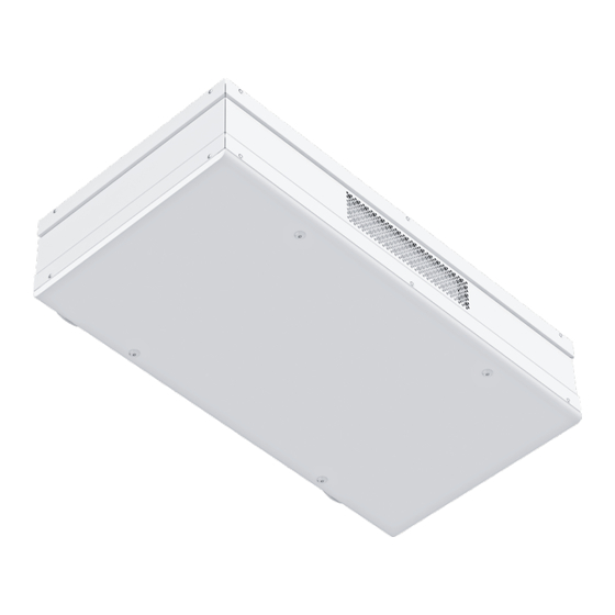
- Page 1 Heat recovery air Handling unit CIVIC EC DB CIVIC EC DBE CIVIC EC DBE2 Single-room heat recovery air handling unit USER’S MANUAL...
-
Page 2: Table Of Contents
Warranty card ....................................25 This user’s manual is a main operating document intended for technical, maintenance, and operating staff. The manual contains information about purpose, technical details, operating principle, design, and installation of the CIVIC EC DB(E; E2) unit and all its modifications. - Page 3 • Do not operate the unit outside the • Do not use damaged equipment or cables temperature range stated in the user’s when connecting the unit to power mains. manual. Do not operate the unit in aggressive or explosive environments.
-
Page 4: Purpose
4 pcs.. Mounting template 1 pc.. Packing box - 1 pc. 1 pc.. DESIGNATION KEY Designation key example: Civic EC DBЕ2 300 A17 Series Electric motor type EC: electronically commutated motors Mounting features D: suspended mounting, horizontal spigots D1: suspended mounting, vertical spigots... -
Page 5: Technical Data
TECHNICAL DATA The unit is designed for indoor application with the ambient temperature ranging from +1 °C up to +40 °C and relative humidity up to 80 %. The unit is rated as a Class I electrical appliance. - Page 6 DIMENSIONS [mm] MODEL CIVIC EC DB 300 CIVIC EC DBE 300 1155 CIVIC EC DBE2 300 1547 CIVIC EC D1B 300 CIVIC EC D1BE 300 1100 1101 CIVIC EC D1BE2 300 CIVIC EC DB 500...
-
Page 7: Design And Operating Principle
DESIGN AND OPERATING PRINCIPLE CIVIC EC DB(E; E2) 300 CIVIC EC DB(E; E2) 500 CIVIC EC DB ... CIVIC EC DBE ... CIVIC EC DBE2 ... Model: · · ·... - Page 8 • Depending on the model the unit includes a pre-heater (CIVIC EC DB(E; E2) and a re-heater (CIVIC EC DBE2) for warming up of the supply air flow. The pre-heater prevents freezing of the heat exchanger and is located in the intake air duct upstream of the heat exchanger.
- Page 9 Air direction in the CIVIC EC DB(E; E2) 300 unit with the closed bypass damper Intake air Exhaust air Supply air Air direction in the CIVIC EC DB(E; E2) 500 unit with the closed bypass damper...
-
Page 10: Installation And Set-Up
INSTALLATION AND SET-UP WHILE INSTALLING THE UNIT ENSURE CONVENIENT ACCESS FOR SUBSEQUENT MAINTENANCE AND REPAIR. BEFORE MOUNTING MAKE SURE THE CASING DOES NOT CONTAIN ANY FOREIGN OBJECTS (E.G. FOIL, PAPER). THE UNIT MUST BE MOUNTED ON A PLANE SURFACE. - Page 11 • With vertical spigots Using the marking, drill the holes and through holes in the wall for the air ducts with the diameter: 220 mm for CIVIC EC DB(E; E2) 300 and 270 mm for CIVIC EC DB(E; E2) 500.
- Page 12 3. Mounting of the unit with horizontal air ducts. Install the air ducts in the wall. The air duct walls must be heat-insulated for freezing prevention. Insert the air ducts in the holes with the minimum slope of 3 mm downwards to the outside.
- Page 13 5. Levelling of the unit with horizontal spigots. Install the unit in a horizontal position using the hand levelling screws.. 6. Mounting of the outer ventilation grilles. Fix the outer ventilation grilles on the outer wall. The grilles are not included in the delivery set and are available as specially ordered accessories.
- Page 14 HV2 HUMIDITY SENSOR MOUNTING Install the HV2 humidity sensor in the extract air duct. Humidity sensor is not included in the delivery set and is available as a specially ordered accessory. To install the humidity sensor first open the air handling unit and fix the sensor on the holder located on the wall of the extract air duct.
- Page 15 CONDENSATE DRAINAGE For the units with a drain pump the flexible hose from the pump must be connected to the sewage system. The drain pump provides timely removal of condensed water from the unit.
-
Page 16: Connection To Power Mains
CONNECTION TO POWER MAINS POWER OFF THE POWER SUPPLY PRIOR TO ANY OPERATIONS WITH THE UNIT. THE UNIT MUST BE CONNECTED TO POWER SUPPLY BY A QUALIFIED ELECTRICIAN. THE RATED ELECTRICAL PARAMETERS OF THE UNIT ARE GIVEN ON THE MANUFACTURER’S LABEL. - Page 17 TH-TUNE (A17) CONTROL PANEL MOUNTING Use a junction box with a minimum diameter of 65 mm and a minimum depth of 31 mm for installation of the back side of the control panel.
- Page 18 The ventilation unit has a built-in automatic control system. The controller integrated in the control unit is the basic component of the control and setup system. The unit is also operated using the th-Tune (A17) or pGD1 (A18) control panel.
- Page 19 • Heat exchanger freeze protection options: - Supply fan shutoff: The fan shuts off, if the exhaust air temperature falls down below 1,5 ˚C. The supply fan turns on 50 seconds (factory setting) after the exhaust air temperature goes up to 4 ˚C.
- Page 20 OPERATION OF THE UNIT WITH THE th-TUNE CONTROL PANEL Button Functions Auto or manual speed control selection. Fan speed selection: setting required speed stage (off, low, medium, high). Scheduler on/off: short pressing. Activation is confirmed with the pictogram.
-
Page 21: Technical Maintenance
TECHNICAL MAINTENANCE DISCONNECT THE UNIT FROM POWER SUPPLY BEFORE ANY MAINTENANCE OPERATIONS! Maintenance operations of the unit are required 3-4 times per year. Maintenance includes general cleaning of the unit and the following operations: 1. - Page 22 2. Heat exchanger maintenance (once per year). Some dust may accumulate on the heat exchanger even in case of regular maintenance of the filters. Regular cleaning of the heat exchanger is required to maintain high heat recovery efficiency. To clean the heat exchanger pull it out of the unit and clean it with compressed air or a vacuum cleaner.
-
Page 23: Troubleshooting
TROUBLESHOOTING TROUBLE POSSIBLE REASONS TROUBLESHOOTING Make sure the power supply line is connected correct. No power supply. Otherwise troubleshoot a connection error. Turn the unit off. Troubleshoot the fan clogging. Clean The fan(s) do(es) not get Motor or impeller clogging. -
Page 24: Manufacturer's Warranty
MANUFACTURER’S WARRANTY The product is in compliance with EU norms and standards on low voltage guidelines and electromagnetic compatibility. We hereby declare that the product complies with the provisions of Electromagnetic Council Directive 2014/30/EU, Low Voltage Directive 2014/35/ EU and CE-marking Directive 93/68/EEC. -
Page 25: Certificate Of Acceptance
This is to certify acceptance of the complete unit delivery with the user’s manual. The warranty terms are acknowledged and accepted. Customer’s Signature Seller’s Stamp INSTALLATION CERTIFICATE The CIVIC EC DB ______ ________ S ______ unit has been connected to power mains pursuant to the requirements stated in the present user’s manual. Seller Address Phone Number Installation Technician’s Full Name... - Page 26 blaubergventilatoren.de...
- Page 27 blaubergventilatoren.de...
- Page 28 blaubergventilatoren.de B177EN-01...
Need help?
Do you have a question about the CIVIC EC DB and is the answer not in the manual?
Questions and answers