Table of Contents
Advertisement
Quick Links
Advertisement
Table of Contents

Related Manuals for BLAUBERG Ventilatoren KOMFORT EC L S6 Series


Summary of Contents for BLAUBERG Ventilatoren KOMFORT EC L S6 Series
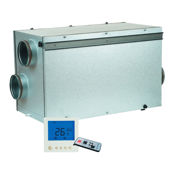
- Page 1 AIR HANDLING UNIT WITH HEAT RECOVERY KOMFORT EC L S6 OPERATION MANUAL...
-
Page 2: Table Of Contents
KOMFORT EC L S6 www.blaubergventilatoren.de CONTENTS Introduction General Safety rules Transportation and storage rules Manufacturer's warranty Design Operating logic Delivery set Technical data Mounting Condensate drainage Control panel mounting Connection to power mains Unit control Troubleshooting and fault handling Technical maintenance Acceptance certificate Connection certificate Warranty card... -
Page 3: Introduction
KOMFORT EC L S6 www.blaubergventilatoren.de BLAUBERG Ventilatoren GmbH is happy to offer your attention the air The transported air must not contain any dust or other solid impurities, sticky handling unit with heat recovery KOMFORT EC L S6. substances or fibrous materials. -
Page 4: Design
KOMFORT EC L S6 www.blaubergventilatoren.de DESIGN The unit has a compact double-skinned aluzinc casing, internally heat- and The plate cross-flow polystyrene heat exchanger is used for heat recovery in sound insulated with a 25 mm mineral wool layer. the unit. The drain pan under the heat exchanger block is used for condensate The casing is equipped with adjustable levelling feet on the bottom panel collection and drainage. -
Page 5: Technical Data
KOMFORT EC L S6 www.blaubergventilatoren.de TECHNICAL DATA Table 1. Technical data of the unit KOMFORT EC L300 KOMFORT EC KOMFORT EC L400 KOMFORT EC L600 Parameters L1/300 S6 Unit voltage [V /50/60 Hz] 1~ 230 Max. unit power [W] Max. unit current [A] Max. -
Page 6: Mounting
KOMFORT EC L S6 www.blaubergventilatoren.de MOUNTING WARNING Safety precautions The unit must be mounted to a rigid and stable structure. The unit must be suspended using anchor bolts. Before starting mounting check that the mounting structure has sufficient loading capacity for the unit weight. The unit mounting is allowed only after power cut-off and full stop of the rotating parts. - Page 7 KOMFORT EC L S6 www.blaubergventilatoren.de Table 4. Service side change 1. Fixing bracket dismantling on current service side: 1. Loosen two triangular screws that retain the fixing bracket. 2. Pull the fixing bracket downwards to remove it from grooves. 3. Dismount the fixing bracket and tighten the triangular screws.
- Page 8 KOMFORT EC L S6 www.blaubergventilatoren.de 5. Limit switch mounting on selected service side: 1. Fix the limit switch fixing bracket with two screws. 2. Fix the limit switch in the fixing bracket. 3. Cover the wires with spade terminals to connect the limit switch.
- Page 9 KOMFORT EC L S6 www.blaubergventilatoren.de The unit design allows mounting to the ceiling, to the wall and to the floor. Note: wall mounting is not applicable for KOMFORT EC L600 The unit is suspended to the ceiling by means of the belts (not included into the delivery set).
-
Page 10: Condensate Drainage
KOMFORT EC L S6 www.blaubergventilatoren.de The unit mounting on the floor is shown in fig. 4. to the unit using triangular screws either through the holes or through a The unit is mounted to the ceiling by means of the belts. Make sure the belt clamp. -
Page 11: Control Panel Mounting
KOMFORT EC L S6 www.blaubergventilatoren.de CONTROL PANEL MOUNTING 1. Unlock the latches with a screw driver through the openings in the bottom. 5. Fix the control panel back cover to the wall. 2. Remove the back cover. 6. Connect the cable to the terminal block. 3. - Page 12 KOMFORT EC L S6 www.blaubergventilatoren.de The unit is rated for connection to single-phase alternating current power The recommended rated automatic switch trip current is 2 A. The mains 230 V / 50/60 Hz. Recommended cable cross section is 0.75 mm The unit is connected to power supply via a pre-wired power cable with a The unit has extra electric connection options.
-
Page 13: Unit Control
KOMFORT EC L S6 www.blaubergventilatoren.de UNIT CONTROL The unit is controlled from the wall-mounted control panel and the remote control, fig. 10. Wall-mounted control panel Remote controller Unit ON/OFF Fan speed UP Fan speed DOWN Medium speed ON High speed ON Low speed ON Scheduled operation ON Timer ON/OFF... - Page 14 KOMFORT EC L S6 www.blaubergventilatoren.de Table 6. Unit control and setup Function Button/Button combination Indication Unit activation/deactivation. Using the wall-mounted control panel. Fig. 11 Fig. 12 Using the remote controller. Speed selection. Low speed 133 m /h, medium speed 270 m /h, high speed 331 m Speed setting up from the wall-mounted control panel (low-medium-high).
- Page 15 KOMFORT EC L S6 www.blaubergventilatoren.de Table 6. Unit control and setup (continued) Function Button/Button combination Indication ATTENTION! Changing the unit parameters results in loss of factory settings for the fan power! ATTENTION! The fan power adjustment is possible from the wall-mounted control panel only! Fan speed adjustment .
- Page 16 KOMFORT EC L S6 www.blaubergventilatoren.de Table 6. Unit control and setup (continued) Function Button/Button combination Indication Filter replacement or cleaning indicator. After 3000 operating hours the control panel display shows the warning filter cleaning or replacement indicator instead of the operating temperature. Clean or replace the filters and then reset the motor meter.
- Page 17 KOMFORT EC L S6 www.blaubergventilatoren.de Table 6. Unit control and setup (continued) Function Button/Button combination Indication Scheduled operation. Each week day has four entries that determine the time for switching the unit to a set fan speed. The timer function always prevails over scheduled operation function.
-
Page 18: Troubleshooting And Fault Handling
KOMFORT EC L S6 www.blaubergventilatoren.de TROUBLESHOOTING AND FAULT HANDLING In case of alarm the unit is turned off and the wall-mounted display shows the alarm indicators, fig. 13. The possible alarms are listed in the table 8. The alarms must be removed ONLY in a service centre or by a service expert, duly authorized for unassisted operations at the units up to 1000V after careful reading of the operation manual. -
Page 19: Technical Maintenance
KOMFORT EC L S6 www.blaubergventilatoren.de TECHNICAL MAINTENANCE WARNING! Cut power supply to the unit off by turning the automatic electric switch QF to OFF position prior to any maintenance operations. Take steps to prevent re-activation of the automatic switch. Regular technical supervision and maintenance of the unit are required to Warning! Consider the unit sharp edges! Fulfil maintenance operations in work gloves! ensure the product long service life and non-stop operation. - Page 20 KOMFORT EC L S6 www.blaubergventilatoren.de 2. Heat exchanger maintenance (once per year). The heat exchanger must be regularly cleaned to maintain high heat exchanger efficiency even in case of the regular filter cleaning. Clean it with warm detergent solution. Remove the heat exchanger from the unit and flush it with warm detergent solution. Install the dry heat exchanger back to the unit.
-
Page 21: Acceptance Certificate
Company: Name: Date Signature WARRANTY CARD KOMFORT EC L300 S6 KOMFORT EC L1/300 S6 KOMFORT EC L400 S6 KOMFORT EC L600 S6 SELLER SALES DATE REPRESENTATIVE IN EU Blauberg Ventilatoren GmbH Aidenbachstr. 52 D-81379 Munich, Germany... - Page 22 KOMFORT EC L S6 www.blaubergventilatoren.de NOTES _______________________________________________________________________________________ _______________________________________________________________________________________ _______________________________________________________________________________________ _______________________________________________________________________________________ _______________________________________________________________________________________ _______________________________________________________________________________________ _______________________________________________________________________________________ _______________________________________________________________________________________ _______________________________________________________________________________________ _______________________________________________________________________________________ _______________________________________________________________________________________ _______________________________________________________________________________________ _______________________________________________________________________________________ _______________________________________________________________________________________ _______________________________________________________________________________________ _______________________________________________________________________________________ _______________________________________________________________________________________ _______________________________________________________________________________________ _______________________________________________________________________________________ _______________________________________________________________________________________ _______________________________________________________________________________________ _______________________________________________________________________________________ _______________________________________________________________________________________ _______________________________________________________________________________________ _______________________________________________________________________________________ _______________________________________________________________________________________ _______________________________________________________________________________________ _______________________________________________________________________________________ _______________________________________________________________________________________ _______________________________________________________________________________________ _______________________________________________________________________________________ _______________________________________________________________________________________ _______________________________________________________________________________________ _______________________________________________________________________________________ _______________________________________________________________________________________ _______________________________________________________________________________________ _______________________________________________________________________________________...
- Page 23 KOMFORT EC L S6 www.blaubergventilatoren.de NOTES _______________________________________________________________________________________ _______________________________________________________________________________________ _______________________________________________________________________________________ _______________________________________________________________________________________ _______________________________________________________________________________________ _______________________________________________________________________________________ _______________________________________________________________________________________ _______________________________________________________________________________________ _______________________________________________________________________________________ _______________________________________________________________________________________ _______________________________________________________________________________________ _______________________________________________________________________________________ _______________________________________________________________________________________ _______________________________________________________________________________________ _______________________________________________________________________________________ _______________________________________________________________________________________ _______________________________________________________________________________________ _______________________________________________________________________________________ _______________________________________________________________________________________ _______________________________________________________________________________________ _______________________________________________________________________________________ _______________________________________________________________________________________ _______________________________________________________________________________________ _______________________________________________________________________________________ _______________________________________________________________________________________ _______________________________________________________________________________________ _______________________________________________________________________________________ _______________________________________________________________________________________ _______________________________________________________________________________________ _______________________________________________________________________________________ _______________________________________________________________________________________ _______________________________________________________________________________________ _______________________________________________________________________________________ _______________________________________________________________________________________ _______________________________________________________________________________________ _______________________________________________________________________________________ _______________________________________________________________________________________...
- Page 24 www.blaubergventilatoren.de Komfort(EC)_L_v.1(3)_EN...
Need help?
Do you have a question about the KOMFORT EC L S6 Series and is the answer not in the manual?
Questions and answers