
Related Manuals for BLAUBERG Ventilatoren KOMFORT EC DE Series


Summary of Contents for BLAUBERG Ventilatoren KOMFORT EC DE Series
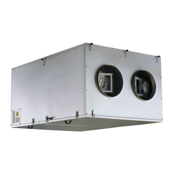
- Page 1 AIR HANDLING UNITS WITH HEAT RECOVERY KOMFORT EC DE OPERATION MANUAL KOMFORT_EC_DE v1(1)_EN.indd 1 07.08.2015 12:39:43...
-
Page 2: Table Of Contents
KOMFORT EC DE www.blaubergventilatoren.de CONTENTS Introduction General Safety rules Transportation and storage rules Manufacturer's warranty Design Operating logic Delivery set Technical data Mounting Condensate drainage Connection to power mains Outdoor duct temperature sensor mounting and connection Duct humidity sensor mounting and connection Control panel mounting Unit control Error code description... -
Page 3: Introduction
KOMFORT EC DE www.blaubergventilatoren.de BLAUBERG Ventilatoren GmbH Company is happy to offer your attention The transported air must not contain any dust or other solid impurities, a suspended heat recovery air handling unit KOMFORT EC DE. sticky substances or fibrous materials. -
Page 4: Design
KOMFORT EC DE www.blaubergventilatoren.de DESIGN The casing made of double-skinned aluzinc panels, internally filled with ventilated premises. The electronic frost protection system based on bypass mineral wool layer of 20 or 25 mm for heat- and sound-insulation. The casing and heater is used to prevent the heat exchanger freezing in cold seasons. has fixing brackets with vibration absorbing connectors for easy installation. -
Page 5: Operating Logic
KOMFORT EC DE www.blaubergventilatoren.de For mounting facilitation and ensuring minimum maintenance distances to the KOMFORT EC DE400/700/1100 unit it is available both in left- and right-handed modifications. RIGHT-HANDED MODIFICATION LEFT-HANDED MODIFICATION (TOP VIEW) (TOP VIEW) Fig. 2. KOMFORT EC DE400/700/1100 modifications OPERATING LOGIC Clean cold air from outside flows to the heat exchanger, where from it is Heat recovery minimizes heat losses caused as compared to traditional... -
Page 6: Technical Data
KOMFORT EC DE www.blaubergventilatoren.de TECHNICAL DATA Table 1. Technical data KOMFORT EC KOMFORT EC KOMFORT EC KOMFORT EC KOMFORT EC Parameters DE400-1.5 DE700-2 DE1100-3.3 DE2000-12 DE4000-21 Supply voltage [V / 50-60 Hz] 1~ 230 3~ 400 Fan power [W] 0,27 0,84 1,98 Fan current [A]... -
Page 7: Mounting
KOMFORT EC DE www.blaubergventilatoren.de MOUNTING WARNING! Safety precautions The unit must be mounted to a rigid and stable structure. The unit must be suspended using anchor bolts. Before starting mounting check that the mounting structure has sufficient loading capacity for the unit weight. The unit mounting is allowed only after power cut-off and full stop of the rotating parts. -
Page 8: Condensate Drainage
KOMFORT EC DE www.blaubergventilatoren.de The unit is suspended using threaded rods and threaded dowels. The unit duct diameters on the outlet side. must be mounted on the even surface to avoid the unit casing distortion and In case of insufficient length or no air ducts cover the unit spigots with a operation disturbances. -
Page 9: Connection To Power Mains
KOMFORT EC DE www.blaubergventilatoren.de CONNECTION TO POWER MAINS WARNING Read the operation manual prior to any electric installations. Connection of the unit to power mains is allowed by a qualified electrician only. The rated electrical parameter are stated on the rating plate. No modifications of internal connections are allowed and will result in void warranty. - Page 10 KOMFORT EC DE www.blaubergventilatoren.de Outside Indoor ТE1 ТE6 FS2 Р1 М2 М1 ТE2 ТE5 12V AC Power 230V AC supply 24V AC Digital input (DI) Digital output (DO) Analogue input (AI) Analogue output (AO) RS485 Sign Name Sign Name Supply air damper Plate heat exchanger Exhaust air damper SM1*...
- Page 11 KOMFORT EC DE www.blaubergventilatoren.de 20 19 18 17 16 15 14 13 12 11 10 9 8 7 6 5 4 3 2 1 Out Gnd E+ B Gnd +12V no c no c N PE N L3 L2 L1 Out Gnd E+ Gnd +12V —...
-
Page 12: Control Panel Mounting
KOMFORT EC DE www.blaubergventilatoren.de OUTER TEMPERATURE SENSOR MOUNTING AND CONNECTION The unit is supplied with an outdoor temperature sensor. subjected to direct solar light. The outdoor temperature sensor mounting is as follows, fig. 13: 4. Install the sensor cover back. 1. - Page 13 KOMFORT EC DE www.blaubergventilatoren.de For the control panel wiring diagram refer to fig. 15. The room temperature recommended cross section of the connecting cable is shown in table 5. The sensor is integrated into the control panel, for that reason the control panel recommended minimum control panel voltage is 11 V.
-
Page 14: Unit Control
KOMFORT EC DE www.blaubergventilatoren.de The control panel includes a lithium cell CR1220 with a limited time 3. Remove the casing cover to enable access to the upper circuit board. resource. Replace the cell. The battery keeps the internal clock running while the unit is disconnected from power mains. - Page 15 KOMFORT EC DE www.blaubergventilatoren.de Table 6. Operation and parameter setup of the unit (continued) Function Indication Fan speed changeover Setting fan speed: Press the AIR FLOW button The unit has four speed stages: - first speed stage; - second speed stage; - third speed stage;...
- Page 16 KOMFORT EC DE www.blaubergventilatoren.de Table 6. Operation and parameter setup of the unit (continued) Function Indication User menu To enter the User menu press MENU in the Main menu. The User menu contains basic menu items and functions for parameter setup: ENG.
- Page 17 KOMFORT EC DE www.blaubergventilatoren.de Table 6. Operation and parameter setup of the unit (continued) Function Indication For navigating in the engineering menu use the following buttons: - moving upwards in the list. - moving downwards in the list. - select the value in the parameter list. - return to user menu.
- Page 18 KOMFORT EC DE www.blaubergventilatoren.de Table 6. Operation and parameter setup of the unit (continued) Function Indication Language selection For language selection in the control panel menu choose the LANGUAGE option in the Engineering menu and press ENTER Select a required language in the list. ...
- Page 19 KOMFORT EC DE www.blaubergventilatoren.de Table 6. Operation and parameter setup of the unit (continued) Function Indication 12 Standby Mode Settings Select the STANDBY MODE item in the Engineering menu and press ENTER Use to select 0 or 1 in AIR FLOW window: •...
- Page 20 KOMFORT EC DE www.blaubergventilatoren.de Table 6. Operation and parameter setup of the unit (continued) Function Indication 16 Adjustment of the temperature sensor integrated into the control panel To adjust the readings of the temperature sensor which is integrated into the Engineering menu select the TEMPERATURE CORRECTION and press ENTER ...
- Page 21 KOMFORT EC DE www.blaubergventilatoren.de Table 6. Operation and parameter setup of the unit (continued) Function Indication To set the AUTO mode enter the User menu and press AUTO ADJUST. In the active TIMER mode the AUTO mode may not be activated as it has lower priority.
- Page 22 KOMFORT EC DE www.blaubergventilatoren.de Table 6. Operation and parameter setup of the unit (continued) Function Indication 21 Motor hours The MOTOR HOURS function is used for cleaning or replacement of the filters. Upon expiry of the set time period the control panel shows the filter cleaning or replacement indicator once per day.
-
Page 23: Error Code Description
KOMFORT EC DE www.blaubergventilatoren.de ERROR CODE DESCRIPTION Table 7. Error code description Error code Description Malfunction of the outdoor temperature sensor. Malfunction of the temperature sensor for the heat exchanger freezing protection. Malfunction of the duct temperature sensor. Malfunction of the duct humidity sensor. Malfunction of the supply fan. -
Page 24: Maintenance
KOMFORT EC DE www.blaubergventilatoren.de TECHNICAL MAINTENANCE WARNING! Cut power supply to the unit off by turning the automatic electric switch QF to OFF position prior to any maintenance operations. Take steps to prevent re-activation of the automatic switch. Warning! Consider the unit sharp edges! Fulfil maintenance Regular technical supervision and maintenance of the unit are required to operations in work gloves! ensure the product long service life and non-stop operation. - Page 25 KOMFORT EC DE www.blaubergventilatoren.de 4. Remove the nine screws that retain the heat exchanger and remove the 4. Remove the fixing screws of the motor fixing bracket. heat exchanger from the unit. Remove the heat exchanger with care. 5. Shift the motor deeper into the unit through the fan intake opening and disconnect the socket connector.
-
Page 26: Troubleshooting And Fault Handling
KOMFORT EC DE www.blaubergventilatoren.de TROUBLESHOOTING AND FAULT HANDLING Table 9. Alarm list and troubleshooting Fault Possible reason Troubleshooting Connect the unit to power mains. Troubleshoot the connection No power supply or wrong connection to power mains. error. The fan does not start when the unit is on. -
Page 27: Acceptance Certificate
Company Name Date Signature WARRANTY CARD KOMFORT EC DE400-1.5 KOMFORT EC DE2000-12 KOMFORT EC DE700-2 KOMFORT EC DE4000-21 KOMFORT EC DE1100-3.3 SELLER SALES DATE REPRESENTATIVE IN EU BLAUBERG Ventilatoren GmbH Aidenbachstr. 52a, D-81379 Munich, Germany KOMFORT_EC_DE v1(1)_EN.indd 27 07.08.2015 12:40:25... - Page 28 www.blaubergventilatoren.de KOMFORT EC DE v.1(1) / EN KOMFORT_EC_DE v1(1)_EN.indd 28 07.08.2015 12:40:25...
Need help?
Do you have a question about the KOMFORT EC DE Series and is the answer not in the manual?
Questions and answers