
Related Manuals for SMC Networks ISE80


Summary of Contents for SMC Networks ISE80
- Page 1 No.PS※※-OMM0003-J PRODUCT NAME Digital Pressure Switch MODEL / Series / Product Number ZSE80(F) ISE80(H)
-
Page 2: Table Of Contents
Table of Contents Safety Instructions Model Indication and How to Order Summary of Product parts Definition and terminology Mounting and Installation Installation Piping Wiring Pressure Setting Measurement mode Function Setting Function selection mode Default setting F0 Units selection function F1 Setting of OUT1 F2 Setting of OUT2 F3 Response time F4 Analogue output / Auto-shift input... -
Page 3: Safety Instructions
Safety Instructions These safety instructions are intended to prevent hazardous situations and/or equipment damage. These instructions indicate the level of potential hazard with the labels of "Caution", "Warning" or "Danger". They are all important notes for safety and must be followed in addition to International Standards (ISO/IEC) , and other safety regulations. - Page 4 Safety Instructions Caution 1.The product is provided for use in manufacturing industries. The product herein described is basically provided for peaceful use in manufacturing industries. If considering using the product in other industries, consult SMC beforehand and exchange specifications or a contract if necessary. If anything is unclear, contact your nearest sales branch.
- Page 5 Operator ♦This operation manual is intended for those who have knowledge of machinery using pneumatic equipment, and have sufficient knowledge of assembly, operation and maintenance of such equipment. Only those persons are allowed to perform assembly, operation and maintenance. ♦Read and understand this operation manual carefully before assembling, operating or providing maintenance to the product.
- Page 6 Caution ■Do not touch the terminals and connectors while the power is on. Otherwise electric shock, malfunction or damage to the product can result. ■After maintenance is complete, perform appropriate functional inspections and leak tests. Stop operation if the equipment does not function properly or there is a leakage of fluid. When leakage occurred from other parts except piping, the product might break.
- Page 7 •Some fluids may generate static electricity when resin piping is used for piping. Take measures against static electricity with equipment when this switch is used in connection with resin piping. Also, the ground should be separate from that of the units that generate strong electromagnetic noise or high frequency, otherwise, the switch can be damaged by static electricity.
- Page 8 ∗Wiring •Do not pull the lead wires. In particular, never lift a Pressure switch equipped with fitting and piping by holding the lead wires. Otherwise damage to the internal parts can result, causing malfunction. •Avoid repeatedly bending or stretching the lead wire, or placing heavy load on them. Repetitive bending stress or tensile stress can cause the sheath of the wire to peel off, or breakage of the wire.
- Page 9 •Do not expose the product to direct sunlight. If using in a location directly exposed to sunlight, shade the product from the sunlight. Otherwise failure or malfunction can result. •Keep within the specified fluid and ambient temperatures range. The fluid and ambient temperatures is 5 to 50 C.
-
Page 10: Model Indication And How To Order
Model Indication and How to Order ○Model Indication and How to order ○Accessories / Part numbers Part number Piping direction Description ZS-24-A Rear piping ZS-24-D Bracket ZS-35-A Bottom piping ZS-35-C Rear piping Panel mount adapter ZS-35-B Bottom piping ZS-35-F Rear piping Panel mount adapter + Front protective cover ZS-35-E Bottom piping... -
Page 11: Summary Of Product Parts
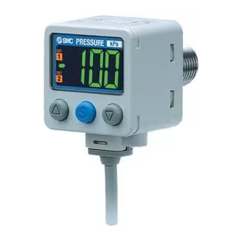
Summary of Product parts ○Names of individual parts Indicator LED (Orange): Displays switch output condition. LCD display: Displays the current status of pressure, setting mode, selected indication unit and error code. Four display modes can be selected: display always in red or green, or display changing from green to red, or red to green, according to the output status. -
Page 12: Definition And Terminology
■Definition and terminology Terms Meaning 2 colours are used to indicate a value, which change according to the output 2-colour display status. When "8" is shown on the display. It is called 7-segment because 8 consists of 7 7-segment display pieces of "- (segments)". - Page 13 Terms Meaning Indication accuracy The deviation between displayed pressure value and the true pressure. The colour of the digital display. There are four choices: normally green, normally Indication colour red, green (off) to red (on), and red (off) to green (on). Indicator LED The LED that turns on when the switch output is on.
- Page 14 Terms Meaning Peak value display Displays the maximum pressure reached up to that moment. Piping-port size The size of the port on the switch body with which a device can be connected. PNP (open collector) output The switch output that uses the PNP transistor for output. Power saving mode The condition in which the display is turned off to reduce current consumption.
-
Page 15: Mounting And Installation
Mounting and Installation ■Installation ○Mounting •Mount the optional bracket and panel mount adapter to the Pressure switch. •When the Pressure switch is to be mounted in a place where water and dust splashes occur, insert a tube (O.D φ4 mm, I.D φ2.5 mm) into the atmospheric vent port of the Pressure switch. ○Mounting with bracket •Fix the bracket to the Pressure switch with the set screws M3 x 5 L (2 pcs.) supplied. - Page 16 ○Mounting with panel mount adapter <Rear piping> <Bottom piping> -15- No.PS※※-OMM0003-J...
-
Page 17: Piping
■Piping ○Connection using screw type piping •Connect suitable piping to the port. •To connect the hexagon socket head plug or fitting to the pressure port, hold the hexagon part of the pressure port with a suitable spanner. The required tightening torque is 12 to 14 Nm. ○Tube attachment •When the Pressure switch is used in a place where water and dust splashes may occur, insert a tube into the atmospheric vent port, and route the other end of the tube to a safe place away from water and dust. -
Page 18: Wiring
•Use a separate route for the Pressure switch wiring and any power or high voltage wiring. Otherwise, malfunction may result due to noise. ○Internal circuit and wiring example Z/ISE80- - - Output specification NPN open collector output type Max. 28 V, 80 mA... - Page 19 -V/-T (Analogue output mode) Switch output PNP open collector output type 2 output Max. 80 mA Residual voltage 1 V or less T: Analogue output 1 to 5 V Output impedance 1 kΩ V: Analogue output 4 to 20 mA Max.
-
Page 20: Pressure Setting
Pressure Setting ■Measurement mode The measurement mode is the condition where the pressure is detected and displayed, and the switch function is operating. This is the basic mode, and other modes should be selected for setting changes and other function settings. Setting the ON and OFF points of the Pressure switch. - Page 21 ∗: The Pressure switch will also output during setting. <How to operate> 1, Press the button once in measurement mode. (Page 19) 2, [P_1] or [n_1] and the set value are displayed in turn. 3, Press the button to change the set value. button is to increase and the button is to decrease.
-
Page 22: Function Setting
Select hysteresis mode or window comparator mode. Hysteresis mode Reversed output Select reversed output. Normal output ISE80: 0.500 MPa ZSE80: -50.5 kPa Pressure setting Set the ON or OFF point of the switch output. ZSE80F: 50.0 kPa ISE80H: 1.000 MPa ISE80: 0.050 MPa... - Page 23 •[F 2] Setting of OUT2 Page Same setting as [F 1] OUT1. The display colour is linked to the setting of OUT1, and can not be set for OUT2. •Other parameter settings Item Page Default setting [F 3] Response time Page 2.5 ms [F 4] Analogue output / Auto-shift input...
-
Page 24: F0 Units Selection Function
Press the button to set. Return to function selection mode. Setting of [F 0] Units selection function completed •Display unit and minimum setting unit Unit ZSE80F ZSE80 ISE80 ISE80H 0.001 (to 1.999) 0.001 0.001 0.001 0.01 (2.00 to) 0.01 (to 19.99) kgf/cm 0.001... -
Page 25: F1 Setting Of Out1
■[F 1] Setting of OUT1 Set output method of OUT1. The output turns on when the pressure exceeds the set value. The default setting of the output set value is the central value between the atmospheric pressure and the upper limit of the rated pressure range. The display colour depends on the condition of OUT1. - Page 26 Setting of hysteresis Press the button to select hysteresis. Press the button to set. Move on to setting of display colour. Setting of display colour Press the button to select display colour. Press the button to set. Return to function selection mode. Setting of [F 1] Setting of OUT1 completed ∗1: The selected parameter becomes effective after pressing the button.
- Page 27 •List of output modes If the set point when the switch output is changed is outside the set pressure range due to switching between normal and reversed output, the hysteresis will automatically be compensated. ∗: The above figure shows the operation of OUT1. For the operation of OUT2, "1"...
-
Page 28: F2 Setting Of Out2
■[F 2] Setting of OUT2 Set output method of OUT2. The display colour is linked to the setting of OUT1, and can not be set for OUT2 <Operation> Press the button in function selection mode to display [F 2]. Press the button. -
Page 29: F4 Analogue Output / Auto-Shift Input
■[F 4] Analogue output / Auto-shift input Auto-shift function This function is available when the analogue output / auto-shift input option has been selected. Auto-shift: A function where the switch output is determined by the change in pressure, relative to a reference set value, when an external signal is input. - Page 30 Setting of effective output Press the button to select effective output. Return to function selection Press the button to set. mode. Setting of [F 4] Analogue output/Auto-shift input completed Conditions and explanations for auto-shift function •Maintain a constant pressure for 5 ms or longer from the end of the auto-shift input signal. •At auto-shift input, [ooo] is displayed for approximate 1 second.
-
Page 31: F5 Display Resolution
■[F 5] Display resolution This function is used to change the pressure display resolution. This can be used to prevent the digits from flickering on the display. <Operation> Press the button in function selection mode to display [F 5]. Press the button. -
Page 32: F7 Fine Adjustment Of Display Value
■[F 7] Fine adjustment of display value This function is used to manually perform fine adjustment of the displayed pressure. It is adjustable within the range ±5% R.D. <Operation> Press the button in function selection mode to display [F 7]. Press the button. -
Page 33: F8 Auto-Preset Function
■[F 8] Auto-preset function When hysteresis mode is selected, the auto-preset function can calculate an optimum pressure value automatically based on the on-going operation. <Operation> Press the button in function selection mode to display [F 8]. Press the button. Move on to setting of auto-preset. Setting of Auto-preset Press the button to select auto-preset. - Page 34 •Auto-preset When auto-preset is selected in function selection mode, the set pressure can be calculated and stored from a measured pressure value. The set value is automatically optimized by repeated pressure changes to the Pressure switch. 1, Selection of auto-preset OUT1 Press the button in measurement mode to display "AP1".
-
Page 35: F9 Power Saving Mode
■[F 9] Power saving mode Power saving mode is selectable. When the Pressure switch is left for 30 seconds with no key operation, it will enter power saving mode (the decimal point and indicator LED (only with the switch output ON) will flash during operation). <Operation>... -
Page 36: F10 Security Code
■[F10] Security code A security code can be selected, which must be entered to unlock the keys when the keys are locked. <Operation> Press the button in function selection mode to display [F10]. Press the button. Move on to setting of security code. Setting of security code [Pin] and the set value are displayed in turn. -
Page 37: Special Function Setting
■Special function setting ■[F98] Setting of all functions All functions can be set, one after the other. <Operation> Press the button in function selection mode to display [F98]. Press the button. Move on to setting of all functions. Setting of all functions [ALL] and the set value are displayed in turn. - Page 38 •Order of function setting Order Function Applicable model Selection of display unit Model with units selection function Select output mode (OUT1) All models Select reversed output (OUT1) All models Setting of pressure (OUT1) All models Setting of hysteresis (OUT1) All models Setting of display colour All models Select output mode (OUT2)
-
Page 39: F99 Reset To The Default Setting
■[F99] Reset to the default setting If the setting of the pressure switch becomes unknown, the default setting can be restored. <Operation> Press the button in function selection mode to display [F99]. Press the button. Move on to reset to the default setting. Reset to the default setting Set the display [ON] by pressing the button,... -
Page 40: Other Settings
Other Settings ○Peak/Bottom value display The maximum (minimum) pressure from when the power was supplied to this moment is detected and updated. In peak/bottom display mode, this pressure is displayed. button is pressed for 1 second or longer, the maximum pressure and "Hi" For peak display, when the starts flashing, and is held. - Page 41 <Operation - With security code input- > •Locking 1, Press the button for 5 seconds or longer in measurement mode. The current setting “UnL” is displayed. 2, Press the button to select keys lock “LoC”. 3, Press the button to store the setting. •Unlocking 1, Press the button for 5 seconds or longer in measurement mode.
- Page 42 •How to change the security code At the time of shipment, the security code is set to “000”, but this can be changed to any number. <Operation> 1, After the Key lock setting has been completed, perform the first three steps in the unlocking procedure (page 40).
-
Page 43: Maintenance
Maintenance How to reset the product after a power cut or forcible de-energizing The setting of the product will remain as it was before a power cut or de-energizing. The output condition is also basically recovered to that before a power cut or de-energizing, but may change depending on the operating environment. -
Page 44: Troubleshooting
Troubleshooting ○Troubleshooting Applicable Pressure switch: ZSE80(F)/ISE80(H) If the cause of the failure cannot be identified and normal operation can be recovered by replacement with a new Pressure switch, this indicates that the Pressure switch itself is faulty. Pressure switch damage can be caused by the operating environment (network construction, etc.), therefore contact SMC. - Page 45 The display is The display Refer to Fault fluctuates not normal No.8 The display Refer to Fault disappears No.9 The display Refer to Fault breaks off No.9 The display Refer to Fault flashes No.10 Pressure display Refer to Fault difference when using No.11 2 or more pressure switches...
- Page 46 ○Faults and countermeasures Fault No. Fault Possible cause Investigation method Countermeasure •Output remains (1) Check the set pressure. (2) Check the operation mode, (1) Reset the pressure Indicator LED Incorrect pressure hysteresis and output type. setting. remains ON. setting (hysteresis mode / window (2) Reset the function •Output remains comparator mode, normal /...
- Page 47 Fault No. Fault Possible cause Investigation method Countermeasure Check that the analogue output is Incorrect wiring Correct the wiring. connected to a load. (1) Check that the correct load is Non-compliance connected. with the load (2) Check that the impedance of the Connect a suitable load.
- Page 48 Fault No. Fault Possible cause Investigation method Countermeasure Check if the power supply voltage is Incorrect power Supply the correct voltage of within the range of 12 to 24 VDC supply 12 to 24 VDC ±10%. ±10%. Check the wiring to the power supply. Check if the brown and blue wires Incorrect wiring are connected to DC(+) and DC(-)
- Page 49 Fault No. Fault Possible cause Investigation method Countermeasure Install a 5 µm filter to prevent foreign matter from entering Check if any foreign matter has Foreign matter the pressure port. Also, clean entered the pressure port. the filter regularly to prevent drainage deposits.
- Page 50 ○Error indication This function is to display error location and content when a problem or an error occurs. Error Name Error Display Error Type Troubleshooting Method Turn the power off and remove the Over current The switch output load current is more than cause of the over current.
-
Page 51: Specification
Specification ■Specifications ISE80 ISE80H ZSE80 ZSE80F Model No. (positive pressure) (positive pressure) (vacuum) (compound) Rated pressure range -0.1 to 1 MPa -0.1 to 2 MPa 0 to –101 kPa -100 to 100 kPa Set pressure range -0.105 to 1.1 MPa -0.105 to 2.2 MPa 10 to –111 kPa... - Page 52 ISE80 ISE80H ZSE80 ZSE80F Model No. (positive pressure) (positive pressure) (vacuum) (compound) Enclosure IP65 Ambient temperature Operation: 0 to 50 C, Storage: -10 to 60 C (No condensation or freezing) Environment Ambient humidity Operation, Storage: 35 to 85% RH (No condensation)
-
Page 53: Dimensions
■Dimensions •Z/ISE80(F)-02/N02/F02/C01/A2/B2/-∗ -C01: Rc1/8 -F02: G1/4 -A2: URJ1/4 -B2: TSJ1/4 -52- No.PS※※-OMM0003-J... - Page 54 •Z/ISE80(F)-02L/N02L/C01L/A2L/B2L/-∗ -C01L: Rc1/8 -A2L: URJ1/4 -B2L: TSJ1/4 -53- No.PS※※-OMM0003-J...
- Page 55 ○With bracket (Rear piping) •ZS-24-A ○With bracket (Rear piping) •ZS-24-D -54- No.PS※※-OMM0003-J...
- Page 56 ○With bracket (Bottom piping) •ZS-35-A -55- No.PS※※-OMM0003-J...
- Page 57 ○Panel mount adapter (Rear piping) •ZS-35-C ○Panel cut-out dimensions -56- No.PS※※-OMM0003-J...
- Page 58 ○Panel mount adapter (Bottom piping) •ZS-35-B ○Panel cut-out dimensions -57- No.PS※※-OMM0003-J...
- Page 59 Revision history A: Revision B: Modified errors in text C: Additional model D: Modified errors in text E: The following item is deleted "The Pressure switch is compulsory turned off for 4 seconds after power supplied." Change of limited warranty and Disclaimer F: Measurement laws are added.
Need help?
Do you have a question about the ISE80 and is the answer not in the manual?
Questions and answers