Table of Contents
Advertisement
Quick Links
RF-BM-MG24B1/B2
www.szrfstar.com
V1.0 - May, 2023
RF-BM-MG24B1 and RF-BM-MG24B2
EFR32MG24 Series
Multiprotocol 2.4 GHz Wireless Module
Version 1.0
Shenzhen RF-star Technology Co., Ltd.
th
May 26
, 2023
All rights reserved. Those responsible for unauthorized reproduction will be prosecuted.
Shenzhen RF-star Technology Co., Ltd.
Page 1 of 21
Advertisement
Table of Contents

Related Manuals for RF-Star EFR32MG24 Series


Summary of Contents for RF-Star EFR32MG24 Series
- Page 1 V1.0 - May, 2023 RF-BM-MG24B1 and RF-BM-MG24B2 EFR32MG24 Series Multiprotocol 2.4 GHz Wireless Module Version 1.0 Shenzhen RF-star Technology Co., Ltd. May 26 , 2023 All rights reserved. Those responsible for unauthorized reproduction will be prosecuted. Shenzhen RF-star Technology Co., Ltd.
-
Page 2: Device Overview
1 Device Overview 1.1 Description RF-BM-MG24B1 and RF-BM-MG24B2 are IoT wireless connectivity modules based on Silicon Labs EFR32MG24 series SoCs. They integrate a 39 MHz crystal and a 32.768 kHz crystal, up to 1536 KB programmable flash, and 256 KB RAM making it possible in many complex applications. -
Page 3: Applications
UART/SPI/SmartCard (ISO7816)/IrDA/I2S 1.3 Applications • Gateway and hubs • Location services • Sensors • Wireless healthcare applications • Smark Lighting • Asset tracking and management • Switches • Electronic Shelf Label (ESL) Shenzhen RF-star Technology Co., Ltd. Page 3 of 21... -
Page 4: Functional Block Diagram
The part numbers are of the form of RF-BM-MG24Bx where the fields are defined as follows: MG24 Company Name Module Version X: Hardware Version RF-STAR Wireless Type Chipset Bluetooth Module SiliconLabs EFR2MG24 Series Figure 2. Part Number Conventions of RF-BM-MG24Bx Shenzhen RF-star Technology Co., Ltd. Page 4 of 21... -
Page 5: Table Of Contents
5.7.3 High Bit Error Rate ..........................15 5.8 Electrostatics Discharge Warnings ......................16 5.9 Soldering and Reflow Condition ......................... 16 6 Optional Package Specification ..........................18 7 Revision History ................................20 8 Contact Us ..................................21 Shenzhen RF-star Technology Co., Ltd. Page 5 of 21... -
Page 6: Module Configuration And Functions
39 MHz, 32.768 kHz Package SMT packaging (1.27-mm half-hole pitch stamp stick) Dimension 23.35 mm × 17.0 mm × 2.2 mm Type of Antenna PCB antenna -40 ℃ ~ +85 ℃ Operating Temperature Shenzhen RF-star Technology Co., Ltd. Page 6 of 21... -
Page 7: Module Pin Diagram
PB04 GPIO PB03 PB03 GPIO PB02 PB02 GPIO PB01 PB01 GPIO PB00 PB00 GPIO VREFN VREFN Dedicated ADC VREF Negative Input VREFP VREFP Dedicated ADC VREF Positive Input PA00 PA00 GPIO Shenzhen RF-star Technology Co., Ltd. Page 7 of 21... - Page 8 Power Supply: 2.2 V ~ 3.8 V (DC-DC mode), 1.8 V ~ 3.8 V (Bypass mode), recommend to 3.3 V Ground Reset pin. Active-low. Internal pullup. RESET RESET_N In DC-DC mode, the max. pull-low voltage is 1.8 V. Shenzhen RF-star Technology Co., Ltd. Page 8 of 21...
-
Page 9: Specifications
3.2 Handling Ratings Table 5. Handling Ratings of RF-BM-MG24Bx Items Condition Typ. Max. Unit Min. Storage Temperature Tstg +125 ℃ Human Body Model ±2000 Moisture Sensitivity Level Charged Device Model ±500 Shenzhen RF-star Technology Co., Ltd. Page 9 of 21... -
Page 10: Setting Of Frequency Offset Register
Find SL_DEVICE_INIT_HFXO_CTUNE, the official default value of SiliconLabs is 140, the value is needed to be changed to for RF-star’s RF-BM-MG24Bx. If the user needs to change to other values, you can directly modify it (Value range: 0 ~ 255). As shown below. Shenzhen RF-star Technology Co., Ltd. Page 10 of 21... -
Page 11: Application, Implementation, And Layout
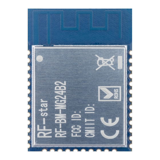
V1.0 - May, 2023 5 Application, Implementation, and Layout 5.1 Module Photos RF-BM-MG24B1 RF-BM-MG24B2 Figure 4. Photos of RF-BM-MG24Bx 5.2 Recommended PCB Footprint Figure 5. Recommended PCB Footprint of RF-BM-MG24Bx (mm) Shenzhen RF-star Technology Co., Ltd. Page 11 of 21... -
Page 12: Schematic Diagram
RF-BM-MG24B1/B2 www.szrfstar.com V1.0 - May, 2023 5.3 Schematic Diagram Figure 6. Schematic Diagram of RF-BM-MG24Bx Shenzhen RF-star Technology Co., Ltd. Page 12 of 21... -
Page 13: Reference Design
Therefore, the layout of the module antenna location and routing is recommended as follows: (1) Place the antenna on the edge (corner) of the PCB. (2) Make sure that there is no signal line or copper foil in each layer below the antenna. Shenzhen RF-star Technology Co., Ltd. Page 13 of 21... -
Page 14: Basic Operation Of Hardware Design
If circumstances permit, appropriate isolation and shielding can be done. 7. Assuming that there are routings of large electromagnetic interference around the module (high-frequency digital, high-frequency analog, power routings), which will also greatly affect the module performance. It is recommended Shenzhen RF-star Technology Co., Ltd. Page 14 of 21... -
Page 15: Trouble Shooting
2. The unsatisfactory power supply may also cause garbled. It is necessary to ensure the power supply's reliability. 3. If the extension wire or feeder wire is of poor quality or too long, the bit error rate will be high. Shenzhen RF-star Technology Co., Ltd. Page 15 of 21... -
Page 16: Electrostatics Discharge Warnings
V1.0 - May, 2023 5.8 Electrostatics Discharge Warnings The module will be damaged by the discharge of static. RF-star suggests that all modules should follow the 3 precautions below: 1. According to the anti-static measures, bare hands are not allowed to touch modules. - Page 17 RF-BM-MG24B1/B2 www.szrfstar.com V1.0 - May, 2023 Figure 9. Recommended Reflow for Lead-Free Solder Shenzhen RF-star Technology Co., Ltd. Page 17 of 21...
-
Page 18: Optional Package Specification
The default package method is . If you need the modules to be shipped by tape & reel, pls contact us in advance. Figure 10. Default Package by Tray Shenzhen RF-star Technology Co., Ltd. Page 18 of 21... - Page 19 RF-BM-MG24B1/B2 www.szrfstar.com V1.0 - May, 2023 Figure 11. Package by Tape & Reel Shenzhen RF-star Technology Co., Ltd. Page 19 of 21...
-
Page 20: Revision History
1. The document will be optimized and updated from time to time. Before using this document, please make sure it is the latest version. 2. To obtain the latest document, please download it from the official website: www.rfstariot.com and www.szrfstar.com. Shenzhen RF-star Technology Co., Ltd. Page 20 of 21... -
Page 21: Contact Us
RF-BM-MG24B1/B2 www.szrfstar.com V1.0 - May, 2023 8 Contact Us SHENZHEN RF-STAR TECHNOLOGY CO., LTD. Shenzhen HQ: Add.: Room 502, Podium Building No. 12, Shenzhen Bay Science and Technology Ecological Park, Nanshan District, Shenzhen, Guangdong, China, 518063 Tel.: 86-755-8632 9829 Chengdu Branch: Add.: N2-1604, Global Center, North No.
Need help?
Do you have a question about the EFR32MG24 Series and is the answer not in the manual?
Questions and answers