
Related Manuals for RF-Star RF-BM-BG22C3


Summary of Contents for RF-Star RF-BM-BG22C3
- Page 1 RF-BM-BG22C3 EFR32BG22C224 Bluetooth 5.2 Low Energy Module Version 1.1 Shenzhen RF-star Technology Co., Ltd. May 26 , 2023 All rights reserved. Those responsible for unauthorized reproduction will be prosecuted.
-
Page 2: Device Overview
PA in the chip enables the module to reach up to 6 dBm TX power. 1.27-mm pitch stamp stick package for easy assembling and cost-effective PCB design. As for the firmware, it can be preprogrammed with an RF-star BLE5.0 serial communication protocol for simple programming. -
Page 3: Applications
• Transmission range: accuracy across temperature range • Security Features - RF-BM-BG22C3: 110 m (@ PCB antenna, 1 - Secure Boot with Root of Trust and Secure Loader Mbps/s); 135 m (@ PCB antenna, 125 kbps/s) • Dimension: 8 mm x 8 mm x 1.82 mm (RTSL) 1.3 Applications... -
Page 4: Part Number Conventions
RF-BM-BG22C3 www.szrfstar.com V1.1 - May, 2023 1.5 Part Number Conventions The part numbers are of the form of RF-BM-BG22C3 where the fields are defined as follows: RF BM BG22 IC Code Company Name EFR32BG22C224 RF-STAR Module Version The C HW Version... -
Page 5: Table Of Contents
5.7.1 Unsatisfactory Transmission Distance ..................17 5.7.2 Vulnerable Module ..........................17 5.7.3 High Bit Error Rate ..........................17 5.8 Electrostatics Discharge Warnings ......................18 5.9 Soldering and Reflow Condition ......................... 18 Shenzhen RF-star Technology Co., Ltd. Page 4 of 23... - Page 6 RF-BM-BG22C3 www.szrfstar.com V1.1 - May, 2023 6 Optional Package Specification ..........................20 7 Revision History ................................22 8 Contact Us ..................................23 Shenzhen RF-star Technology Co., Ltd. Page 5 of 23...
-
Page 7: Module Configuration And Functions
RF-BM-BG22C3 www.szrfstar.com V1.1 - May, 2023 2 Module Configuration and Functions 2.1 Module Parameters Table 1. Parameters of RF-BM-BG22C3 Chipset EFR32BG22C224F512GM32-C DC-DC mode: 2.2 V ~ 3.8 V, recommended to 3.3 V Supply Power Voltage Bypass mode: 1.8 V ~ 3.8 V, recommended to 3.3 V... -
Page 8: Module Pin Diagram
RF-BM-BG22C3 www.szrfstar.com V1.1 - May, 2023 2.2 Module Pin Diagram Figure 3. Pin Diagram of RF-BM-BG22C3 2.3 Pin Functions Table 2. Pin Functions of RF-BM-BG22C3 Name Chip Pin Pin Type Description PA06 GPIO PA06 PA05 PA05 GPIO PA04 PA04 GPIO... - Page 9 RF-BM-BG22C3 www.szrfstar.com V1.1 - May, 2023 PB01 PB01 GPIO GPIO PC05 PC05 2.2 V ~ 3.8 V, recommended to 3.3 V Ground EXT_ANT EXT_ANT External antenna pin. Shenzhen RF-star Technology Co., Ltd. Page 8 of 23...
-
Page 10: Specifications
The functional operation does not guarantee performance beyond the limits of the conditional parameter values in the table below. Long-term work beyond this limit will affect the reliability of the module more or less. Table 3. Recommended Operating Conditions of RF-BM-BG22C3 Items Condition Typ. -
Page 11: Setting Of Frequency Offset Register
Oen the project, find the Project Explorer window, and open the project folder, as shown in the following figure. Then choose the config folder, find the sl_device_init_hfxo_config.h file, and double-click to open it, as shown in the figure below. Shenzhen RF-star Technology Co., Ltd. Page 10 of 23... - Page 12 Find SL_DEVICE_INIT_HFXO_CTUNE, the official default value of SiliconLabs is 140, RF-star changes it to 72 according to the requirements of the development board hardware RF part. Remark: This is the value for RF-star’s standard EFR32BG22 series modules, the value of the other customized products needs to be confirmed.
-
Page 13: Application, Implementation, And Layout
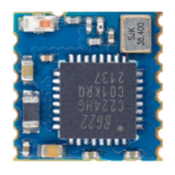
RF-BM-BG22C3 www.szrfstar.com V1.1 - May, 2023 5 Application, Implementation, and Layout 5.1 Module Photos Figure 4. Photos of RF-BM-BG22C3 5.2 Recommended PCB Footprint Figure 5. Recommended PCB Footprint of RF-BM-BG22C3 (mm) Shenzhen RF-star Technology Co., Ltd. Page 12 of 23... -
Page 14: Schematic Diagram
RF-BM-BG22C3 www.szrfstar.com V1.1 - May, 2023 5.3 Schematic Diagram Figure 6. Schematic Diagram of RF-BM-BG22C3 5.4 Reference Design Figure 7. Reference Design of RF-BM-BG22Cx Shenzhen RF-star Technology Co., Ltd. Page 13 of 23... -
Page 15: Antenna
Note: The hollow-out position is based on the antenna used. 5.5.2 Antenna Output Mode Modification 1. RF-BM-BG22C3 has two antenna output modes. The one is an onboard chip antenna and the other is a stamp half- hole output (ANT pin, see pin function table for details). -
Page 16: External Antenna Design Recommendation Of The Half-Hole Ant Pin
. If you want to use the external antenna by the ANT pin, pls disassembly the chip antenna. The location of the chip antenna is shown in the figure below. Figure 9. Antenna Output Mode Change of RF-BM-BG22C3 5.5.3 External Antenna Design Recommendation of the Half-Hole ANT Pin 1. -
Page 17: Basic Operation Of Hardware Design
6. Assuming that there are devices with large electromagnetic interference around the module, which will greatly affect the module performance. It is recommended to stay away from the module according to the strength of the Shenzhen RF-star Technology Co., Ltd. Page 16 of 23... -
Page 18: Trouble Shooting
5.7.3 High Bit Error Rate 1. There are co-channel signal interferences nearby. It is recommended to be away from the interference sources or modify the frequency and channel to avoid interferences. Shenzhen RF-star Technology Co., Ltd. Page 17 of 23... -
Page 19: Electrostatics Discharge Warnings
3. If the extension wire or feeder wire is of poor quality or too long, the bit error rate will be high. 5.8 Electrostatics Discharge Warnings The module will be damaged by the discharge of static. RF-star suggests that all modules should follow the 3 precautions below: 1. - Page 20 RF-BM-BG22C3 www.szrfstar.com V1.1 - May, 2023 Figure 13. Recommended Reflow for Lead-Free Solder Shenzhen RF-star Technology Co., Ltd. Page 19 of 23...
- Page 21 The default package method is . If you need the modules to be shipped by tape & reel, pls contact us in advance. Figure 14. Default Package by Tray Shenzhen RF-star Technology Co., Ltd. Page 20 of 23...
- Page 22 RF-BM-BG22C3 www.szrfstar.com V1.1 - May, 2023 Figure 15. Package by Tape & Reel Shenzhen RF-star Technology Co., Ltd. Page 21 of 23...
- Page 23 1. The document will be optimized and updated from time to time. Before using this document, please make sure it is the latest version. 2. To obtain the latest document, please download it from the official website: www.rfstariot.com and www.szrfstar.com. Shenzhen RF-star Technology Co., Ltd. Page 22 of 23...
- Page 24 RF-BM-BG22C3 www.szrfstar.com V1.1 - May, 2023 8 Contact Us SHENZHEN RF-STAR TECHNOLOGY CO., LTD. Shenzhen HQ: Add.: Room 502, Podium Building No. 12, Shenzhen Bay Science and Technology Ecological Park, Nanshan District, Shenzhen, Guangdong, China, 518063 Tel.: 86-755-8632 9829 Chengdu Branch: Add.: N2-1604, Global Center, North No.
Need help?
Do you have a question about the RF-BM-BG22C3 and is the answer not in the manual?
Questions and answers