Table of Contents

Related Manuals for RF-Star RF-BM-4044B2


Summary of Contents for RF-Star RF-BM-4044B2
- Page 1 RF-BM-4044B2 and RF-BM-4044B3 CC2640R2FRSM Bluetooth 5.1 Low Energy Module Version 1.1 Shenzhen RF-star Technology Co., Ltd. May 26 , 2023 All rights reserved. Those responsible for unauthorized reproduction will be prosecuted.
-
Page 2: Device Overview
15.2 mm x 11.2 mm x 2.1 mm 1.2 Description RF-BM-4044B2 and RF-BM-4044B3 modules are designed based on CC2640R2FRSM System-on-Chip, which fully supports the single-mode Bluetooth 5.1 Low Energy operation. The module contains a 32-bit ARM Cortex-M3 processor, with a working frequency of 48.0 MHz. The module has rich peripherals function libraries, and a unique ultra-low power sensor controller, which is fit for connecting the external sensors in sleep mode or acquiring analog and digital data independently. -
Page 3: Applications
RF-BM-4044B2/B3 www.szrfstar.com V1.1 - May, 2020 - Programmable current source - RF-BM-4044B2: 16.6 mm x 11.2 mm x 1.7 - UART - 2 × SSI (SPI, MICROWIRE, TI) - RF-BM-4044B3: 15.2 mm x 11.2 mm x 2.1 - I2C • Certificate... -
Page 4: Part Number Conventions
RF-BM-4044B2/B3 www.szrfstar.com V1.1 - May, 2020 1.6 Part Number Conventions The part numbers are of the form of RF-BM-4044B2/4044B3 where the fields are defined as follows: 4044 Company Name Module Version B2: The Second Version(PCB) RF-STAR B3: The Third Version(IPEX) -
Page 5: Table Of Contents
4.6 Basic Operation of Hardware Design ...................... 15 4.7 Trouble Shooting .............................. 16 4.7.1 Unsatisfactory Transmission Distance ..................16 4.7.2 Vulnerable Module ..........................16 4.7.3 High Bit Error Rate ..........................16 4.8 Electrostatics Discharge Warnings ......................17 Shenzhen RF-star Technology Co., Ltd. Page 4 of 24... - Page 6 5 Optional Package Specification ..........................19 6 Certification ..................................21 6.1 FCC ..................................21 6.2 RoHS ..................................21 6.3 SRRC ................................... 22 7 Revision History ................................23 8 Contact Us ..................................24 Shenzhen RF-star Technology Co., Ltd. Page 5 of 24...
-
Page 7: Module Configuration And Functions
128 KB Package SMT Packaging (1.27-mm half-hole pitch stamp stick) Frequency Error ±20 kHz RF-BM-4044B2: 16.6 mm x 11.2 mm x 1.7 mm Dimension RF-BM-4044B3: 15.2 mm x 11.2 mm x 2.1 mm RF-BM-4044B2: PCB antenna Type of Antenna RF-BM-4044B3: IPEX connector Operating Temperature -40 ℃... -
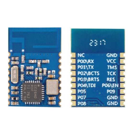
Page 8: Module Pin Diagram
RF-BM-4044B2/B3 www.szrfstar.com V1.1 - May, 2020 2.2 Module Pin Diagram RF-BM-4044B2 RF-BM-4044B3 Figure 3. Pin Diagram of RF-BM-4044B2/4044B3 2.3 Pin Functions Table 3. Pin Functions of RF-BM-4044B2/4044B3 Name Chip Pin Pin Type Description VDDZ Power Power supply 1.8 V ~ 3.8 V, recommend 3.3 V... - Page 9 RF-BM-4044B2/B3 www.szrfstar.com V1.1 - May, 2020 DIO_2 Digital I/O GPIO, Sensor Controller, high-drive capacity DIO_1 Digital I/O GPIO, Sensor Controller, high-drive capacity DIO_0 Digital I/O GPIO, Sensor Controller, high-drive capacity Shenzhen RF-star Technology Co., Ltd. Page 8 of 24...
-
Page 10: Specifications
Charged Device Model ±750 3.3 RF Test When measured on the RF-BM-4044B2 reference design with T A = 25 ℃, V BAT = 3.3 V with DC/DC, the channel of (2442 MHz) enabled unless otherwise noted. Table 6. Table of RF Test... -
Page 11: Application, Implementation, And Layout
RF-BM-4044B2/B3 www.szrfstar.com V1.1 - May, 2020 4 Application, Implementation, and Layout 4.1 Module Photos RF-BM-4044B2 RF-BM-4044B3 Figure 4. Photos of RF-BM-4044B2/4044B3 4.2 Recommended PCB Footprint RF-BM-4044B2 Shenzhen RF-star Technology Co., Ltd. Page 10 of 24... -
Page 12: Schematic Diagram
RF-BM-4044B2/B3 www.szrfstar.com V1.1 - May, 2020 RF-BM-4044B3 Figure 5. Recommended PCB Footprint of RF-BM-4044B2/4044B3 (mm) 4.3 Schematic Diagram Figure 6. Schematic Diagram of RF-BM-4044B2/4044B3 Shenzhen RF-star Technology Co., Ltd. Page 11 of 24... -
Page 13: Reference Design
V1.1 - May, 2020 4.4 Reference Design Note: EN low enable. Figure 7. Reference Design of RF-BM-4044B2/4044B3 4.5 Antenna 4.5.1 Antenna Design Recommendation 1. The antenna installation structure has a great influence on the module performance. It is necessary to ensure the antenna is exposed and preferably vertically upward. -
Page 14: External Antenna Design Recommendation Of The Half-Hole Ant Pin
The traces are as short as possible, and 135° or arc traces are used as much as possible. No vias are used to change layers. More GND vias are placed around the RF traces. Figure 9. Reference Design of the External Antenna Figure 10. Reference Design of the External Antenna Traces Shenzhen RF-star Technology Co., Ltd. Page 13 of 24... -
Page 15: Ipex Connector Specification
Figure 11. SI9000 Impedance Calculation Diagram 5.4.3 IPEX Connector Specification RF-BM-4044B3 module is integrated the IPEX version 1 antenna seat, the specification of the antenna seat is as follows: Figure 12. Specification of Antenna Seat Shenzhen RF-star Technology Co., Ltd. Page 14 of 24... -
Page 16: Basic Operation Of Hardware Design
6. Assuming that there are devices with large electromagnetic interference around the module, which will greatly affect the module performance. It is recommended to stay away from the module according to the strength of the interference. If circumstances permit, appropriate isolation and shielding can be done. Shenzhen RF-star Technology Co., Ltd. Page 15 of 24... -
Page 17: Trouble Shooting
1. There are co-channel signal interferences nearby. It is recommended to be away from the interference sources or modify the frequency and channel to avoid interferences. 2. The unsatisfactory power supply may also cause garbled. It is necessary to ensure the power supply's reliability. Shenzhen RF-star Technology Co., Ltd. Page 16 of 24... -
Page 18: Electrostatics Discharge Warnings
3. If the extension wire or feeder wire is of poor quality or too long, the bit error rate will be high. 4.8 Electrostatics Discharge Warnings The module will be damaged by the discharge of static. RF-star suggests that all modules should follow the 3 precautions below: 1. - Page 19 RF-BM-4044B2/B3 www.szrfstar.com V1.1 - May, 2020 Figure 14. Recommended Reflow for Lead-Free Solder Shenzhen RF-star Technology Co., Ltd. Page 18 of 24...
-
Page 20: Optional Package Specification
The default package method is . If you need the modules to be shipped by tape & reel, pls contact us in advance. Figure 15. Default Package by Tray Shenzhen RF-star Technology Co., Ltd. Page 19 of 24... - Page 21 RF-BM-4044B2/B3 www.szrfstar.com V1.1 - May, 2020 Figure 16. Package by Tape & Reel Shenzhen RF-star Technology Co., Ltd. Page 20 of 24...
-
Page 22: Certification
This device complies with part 15 of the FCC Rules. Operation is subject to the following two conditions: (1) This device may not cause harmful interference, and (2) this device must accept any interference received, including interference that may cause undesired operation. FCC ID: 2ABN2-BM4044B2 Figure 17. FCC certificate of RF-BM-4044B2 6.2 RoHS RoHS Report No.: U00201190830003E Query Password: QW6480 Figure 18. -
Page 23: Srrc
RF-BM-4044B2/B3 www.szrfstar.com V1.1 - May, 2020 6.3 SRRC SRRC CMIIT ID: 2019DP6529 Figure 19. SRRC Certificate of RF-BM-4044B2 Shenzhen RF-star Technology Co., Ltd. Page 22 of 24... -
Page 24: Revision History
1. The document will be optimized and updated from time to time. Before using this document, please make sure it is the latest version. 2. To obtain the latest document, please download it from the official website: www.rfstariot.com and www.szrfstar.com. Shenzhen RF-star Technology Co., Ltd. Page 23 of 24... -
Page 25: Contact Us
RF-BM-4044B2/B3 www.szrfstar.com V1.1 - May, 2020 8 Contact Us SHENZHEN RF-STAR TECHNOLOGY CO., LTD. Shenzhen HQ: Add.: Room 502, Podium Building No. 12, Shenzhen Bay Science and Technology Ecological Park, Nanshan District, Shenzhen, Guangdong, China, 518063 Tel.: 86-755-8632 9829 Chengdu Branch: Add.: N2-1604, Global Center, North No.
Need help?
Do you have a question about the RF-BM-4044B2 and is the answer not in the manual?
Questions and answers