Table of Contents
Advertisement
G a s F u r n a c e S i l i c o n
G a s F u r n a c e S i l i c o n
N i t r i d e I g n i t o r M o d e l s
N i t r i d e I g n i t o r M o d e l s
© 2001 American Standard Inc. All rights reserved.
© 2001 American Standard Inc. All rights reserved.
• Single and Two Stage Models
• Single and Two Stage Models
• Variable Speed Vent Models
• Variable Speed Vent Models
• Variable Speed Blower Motor
• Variable Speed Blower Motor
• Test Procedures
• Test Procedures
• Direct Vent
• Direct Vent
1
Advertisement
Table of Contents

Related Manuals for American Standard 50A65-475


Summary of Contents for American Standard 50A65-475
- Page 1 • Variable Speed Vent Models • Variable Speed Blower Motor • Variable Speed Blower Motor • Test Procedures • Test Procedures • Direct Vent • Direct Vent © 2001 American Standard Inc. All rights reserved. © 2001 American Standard Inc. All rights reserved.
- Page 2 Note: This publication is general in nature and is intended for INSTRUCTIONAL PURPOSES ONLY. It is not to be used for equipment selection, application, installation, or specific service procedures.
-
Page 3: Table Of Contents
Contents Model Nomenclature ................................3 Silicon Nitride Ignitor ................................4 Component Identification – Single Stage 80% Upflow/Horizontal ................... 6 Integrated Furnace Control – CNT02854 – Superseded to CNT03076 ................8 Integrated Furnace Control – CNT03076 ..........................9 Single Stage 50A65-474 Sequence of Operation ......................10 Wiring Schematic –... - Page 4 IFC Diagnostic Codes If 24 VAC “R – B” is less than 20 VAC or greater than 30 VAC, the control system will not function correctly. Diagnostic Codes LED Flash Indicates Slow Flash Normal Stand By. Fast Flash Normal with a Call for Heat. Continuous ON Internal Fault in the IFC.
-
Page 5: Model Nomenclature
Model Nomenclature U C 0 4 0 C 9 2 4 A Furnace Configuration U = Upflow/Horizontal D = Downflow/Horizontal Type D = Induced Draft – 80% AFUE E = 78%/80% AFUE X = Direct Vent Condensing Y = Direct Vent Condensing Variable Speed Blower Heating Input MBTUH Example: 040 = 40,000 MBTUH Major Design Change... -
Page 6: Silicon Nitride Ignitor
Silicon Nitride Ignitor Abbreviation SiNi Ignitor Composition: 1. Tungsten Paste Element 2. Silicon Nitride Ceramic Insulators SiNi Tungsten Element Insulators Part # IGN 0104 Silicon Nitride Ignitor... - Page 7 Silicon Nitride Ignitor The ignitor used with this series of White-Rodgers con- will lock out and cause the diagnostic status L.E.D. trols is constructed of a tungsten heater element and to flash six times for control #50A61-605 CNT2536 silicon nitride ceramic insulators. The voltage rating of only.
-
Page 8: Component Identification - Single Stage 80% Upflow/Horizontal
Component Identification Single Stage 80% Upflow/Horizontal INDUCED DRAFT BLOWER (1 SPEED) HIGH TEMPERATURE PRESSURE SWITCH LIMIT (TCO) GAS VALVE HIGH VOLTAGE (ONE STAGE) AND ACCESSORY ROLL-OUT BIMETAL HOOK-UP RESETABLE ROLL-OUT BI-METAL HOT SURFACE RESETABLE IGNITOR FLAME SENSOR INSHOT BURNER DOOR SWITCH TRANSFORMER INTEGRATED FURNACE CONTROL... - Page 9 Component Identification Single Stage 90% Upflow/Horizontal HIGH TEMPERATURE LIMIT SWITCH BURNER SIGHT GLASS ELECTRICAL JUNCTION BOX FLAME ROLL-OUT SWITCH (MANUAL RESET) GAS VALVE INDUCED DRAFT BLOWER PRESSURE SWITCH TCO (LIMIT) DOOR SWITCH COOL-H PARK PARK LINE-H HEAT-H EAC-H XFMR-H HUM-H LINE-N HUM-N TRANSFORMER...
-
Page 10: Integrated Furnace Control - Cnt02854 - Superseded To Cnt03076
Integrated Furnace Control CNT2854 – Superseded to CNT03076 Used on 80% and 90% Furnaces Single Stage Heat – Silicon Nitride Hot Surface Ignitor Single Speed Vent Motor and Standard Four Speed Blower COOL-H PARK PARK LINE-H HEAT-H EAC-H XFMR-H HUM-H LINE-IN Plug # E20 HUM-N... -
Page 11: Integrated Furnace Control - Cnt03076
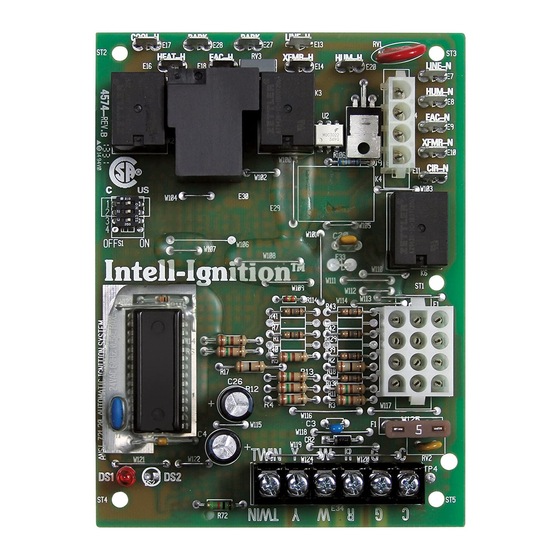
Single Stage Heat – Silicon Nitride Hot Surface Ignitor Single Speed Vent Motor and Standard Four Speed Blower with Single Wire Twinning Feature COOL-H PARK PARK LINE-H HEAT-H EAC-H XFMR-H HUM-H LINE-IN HUM-N EAC-N XFMR-N CIR-N 5 AMPS TWIN 50A65-475 CNT03076 TWIN... -
Page 12: Single Stage 50A65-474 Sequence Of Operation
Single Stage 50A65-474 Sequence of Operation White-Rodgers Integrated Furnace up. The control then switches on 24 volts to the gas Controls 50A65-474 with Silicon Nitride valve “MV” terminal #1 a. The redundant and main Hot Surface Ignitor (SiNi HSI) – Part No. solenoids are energized allowing gas flow and main CNT02854, Superseded to CNT03076 burner ignition. -
Page 13: Wiring Schematic - Single Stage 80% And 90
Wiring Schematic Single Stage 80% and 90% 120 VOLT, 60 HZ., 1 PH. POWER SUPPLY PER LOCAL CODES COOL I.D. “A” HEAT DOOR BLOWER SWITCH “B” PARK MTR. “C” PARK HOT 120VAC BK/1 LINE BK/4 XFMR BK/3 OPTIONAL BK/2 CIR N WH/1 LINE N NEUTRAL 120VAC... -
Page 14: Component Identification - Two Stage 80% Upflow/Horizontal
Component Identification Two Stage 80% Upflow/Horizontal 1ST STAGE INDUCED DRAFT PRESSURE SWITCH BLOWER (2 SPEED) 2ND STAGE HIGH TEMPERATURE PRESSURE SWITCH LIMIT (TCO) GAS VALVE HIGH VOLTAGE (2 STAGE) AND ACCESSORY HOOK-UP ROLL-OUT BI-METAL RESETABLE ROLL-OUT BI-METAL RESETABLE HOT SURFACE IGNITOR FLAME SENSOR INSHOT BURNER... -
Page 15: Integrated Furnace Control - Cnt03077
Integrated Furnace Control – CNT03077 NEUTRAL LINE XFMR CIRC XFMR LINE PARK COOL HI HEAT LO HEAT Plug # E4 5. IGN-N LINE XFMR CIRC XFMR LINE PARK COOL HI HEAT LO HEAT 4. IND-N DIP SWITCH (S1) 3. IND-LO Cool “Off”... -
Page 16: Two Stage 50M61-495 Sequence Of Operation
Two Stage 50M61-495 Sequence of Operation White-Rodgers Integrated Furnace Control 50M61-495 Models valve solenoids ga are de-energized. The control When the service disconnect 1 is in the “ON” position, will begin an interpurge cycle and adds additional seconds to the hot surface ignitor warm-up timing power is applied through the blower door interlock switch 6 to the controls line voltage input terminals 8 (see note). -
Page 17: Wiring Schematic - Two Stage Heat
Wiring Schematic Two Stage Heat (White-Rodgers 50M61-495 Series Integrated Furnace Control) 120 VOLT, 60 HZ., 1 PH. POWER SUPPLY PER LOCAL CODES 50M51-495 INTEGRATED FURNACE CONTROL COOL I.D. “A” PARK DOOR BLOWER SWITCH “B” HEAT LO MTR. “C” HEAT HI HOT 120VAC BK/1 LINE... -
Page 18: Component Identification - Two Stage/Two Speed Vent Motor And Variable Speed Indoor Motor
Component Identification 80% Two Stage/Two Speed Vent Motor and Variable Speed Indoor Motor 1ST STAGE INDUCED DRAFT PRESSURE SWITCH BLOWER (2 SPEED) 2ND STAGE HIGH TEMPERATURE PRESSURE SWITCH LIMIT (TCO) GAS VALVE HIGH VOLTAGE (2 STAGE) AND ACCESSORY HOOK-UP ROLL-OUT BI-METAL RESETABLE ROLL-OUT BI-METAL RESETABLE... -
Page 19: Integrated Furnace Control - Cnt03078
Integrated Furnace Control – CNT03078 NEUTRAL LINE XFMR CIRC XFMR LINE PARK COOL HI HEAT LO HEAT Plug # E4 DIP SWITCH (S1) LINE XFMR CIRC XFMR LINE PARK COOL HI HEAT LO HEAT Heat “Off” Delay 5. IGN-N Secs 4. -
Page 20: Two Stage Variable Speed Sequence Of Operation
Two Stage Variable Speed Sequence of Operation White-Rodgers 50V61 Series Integrated seconds (see note) to the hot surface ignitor warm-up Furnace Control timing. The control energizes the gas valve for the second attempt to establish main burner ignition. When the service disconnect 1 is in the “ON” position, If again flame current is not sensed by the control power is applied through the blower door interlock within the trial for ignition period (see note), the... -
Page 21: Wiring Schematic - Two Stage Variable Speed Indoor Blower
Wiring Schematic Two Stage Variable Speed Indoor Blower 120 VOLT, 60 HZ., 1 PH. POWER SUPPLY PER LOCAL CODES BK/8 WH/7 DOOR BLOWER GR/BK SWITCH 50V61-507 MOTOR CNT03078 BK/2 OPTIONAL BK/3 JUMPER HOT 120VAC BK/1 LINE YL/BK BK/7 CIRC XFMR BK/4 LINE N WH/1... -
Page 22: Component Identification - Two Stage 90% Variable Speed Vent Motor And Four Speed Indoor Motor
Component Identification Two Stage 90% Variable Speed Vent Motor and 4 Speed Indoor Motor HIGH TEMPERATURE LIMIT SWITCH BURNER SIGHT GLASS ELECTRICAL JUNCTION BOX FLAME ROLL-OUT SWITCH (MANUAL RESET) TWO STAGE GAS VALVE 2ND STAGE PRESSURE SWITCH VARIABLE SPEED 1ST STAGE VENT MOTOR PRESSURE AND BLOWER... -
Page 23: Integrated Furnace Control - Cnt02871
Integrated Furnace Control – CNT2871 Two Stage Heat – Silicon Nitrate Surface Ignitor Variable Speed Vent Motor and Standard Four Speed Blower DIAGNOSTIC LINE-N CIR-N EAC-N HUM-N Plug # E2 INDUCER Plug # E4 GREEN 1. RPM/SOA Vent 1. Transformer Motor Report Line Neutral TEST JUMPER... -
Page 24: Variable Speed Vent Motor
Variable Speed Vent Motor This microprocessor based variable speed motor The pressure switches are constantly monitored during has an adaptive learning routine, which causes the furnace operation. If a pressure switch opens during the motor to learn the optimum operating speed for a run cycle, the motor speeds up to close the switch low and high fire. - Page 25 Variable Speed Vent Motor A new Inducer Motor Assembly has been introduced in missions. As shown in the illustration, the motor is the 90% furnace line using the variable speed inducer mounted horizontally with the isolators above and motors. This assembly features vibration isolators below the motor.
-
Page 26: Two Stage 50V65 Sequence Of Operation
Two Stage 50V65 Sequence of Operation White-Rodgers Integrated Furnace Control are de-energized. The control will begin an interpurge 50V65-495 Models – Part No. CNT02871 cycle and add additional AC sine wave cycles to the hot surface ignitor warm-up timing cycle (see SiNi HSI When the service disconnect 1 is in the “ON”... -
Page 27: Two Stage Heat/Variable Speed Vent Motor/Standard Indoor Blower
Two Stage Heat/Variable Speed Vent Motor/Std. Indoor Blower 115 VOLT, 60 HZ., 1 PH. POWER SUPPLY PER LOCAL CODES VENT MOTOR DOOR SWITCH RPM/SOA 13 VDC HI EN I.D. FAN MOTOR JPR1 LINE N LO EN CIR N #50V65-495 HPS/PS2 EAC N PART #CNT2871 LPS/PS1... -
Page 28: Component Identification - Two Stage 90% Variable Speed Vent Motor And Variable Speed Indoor Blower
Component Identification Two Stage 90% Variable Speed Vent Motor and Variable Speed Indoor Blower HIGH TEMPERATURE LIMIT SWITCH BURNER SIGHT GLASS ELECTRICAL JUNCTION BOX FLAME ROLL-OUT SWITCH (MANUAL RESET) TWO STAGE GAS VALVE 2ND STAGE PRESSURE SWITCH VARIABLE SPEED 1ST STAGE VENT MOTOR PRESSURE AND BLOWER... -
Page 29: Integrated Furnace Control - Cnt02536
Integrated Furnace Control – CNT02536 CR22 Plug # E10 1. RPM/SOA Vent Motor Report Line Out 2. +13 V.D.C. Power CR28 3. Ground LINE-N CR21 CR24 4. Inducer Low Speed On/Off Line 1 V.D.C. On, 11 V.D.C. Off CIR-N Line Voltage Neutral 5. -
Page 30: Two Stage 50A61 Sequence Of Operation
Two Stage 50A61 Sequence Of Operation White-Rodgers Integrated Furnace Control and add additional AC sine wave cycles to the hot 50A61-605 Model – Part No. CNT02536 surface ignitor warm-up timing cycle (see SiNi HSI write up). The control energizes the gas valve for the When the service disconnect 1 is in the “ON”... -
Page 31: Two Stage Variable Speed Vent Motor And Blower
Two Stage Variable Speed Vent Motor and Blower 115 VOLT, 60 HZ., 1 PH. POWER SUPPLY PER LOCAL CODES DOOR SWITCH BK/1 BK/8 WH/7 VENT SWITCH #3 GR/BK MOTOR CONTROL HEAT OFF DELAY (SECONDS) LINE N MTR. DELAY WH/BK RPM/SOA WH/7 CIR N BK/WH... -
Page 32: Two Stage/Variable Speed Vent And Variable Speed Blower Motor Models
Two Stage V/S Vent and V/S Blower Motor Models Sequence of Operation Second Stage Satisfied, First Stage Still Calling First Stage Heat The IFC will remove the high speed signal to the When the integrated furnace control, IFC, receives a call variable speed vent motor and the indoor blower;... -
Page 33: White-Rodgers Self Diagnostic Features
White-Rodgers Self Diagnostic Features The integrated furnace control tests for internal and • The LED will flash “SLOW” , 1⁄4 second “ON” and 3⁄4 external faults before allowing a heating sequence to second “OFF” , with system in stand-by (power on). begin. -
Page 34: Ignition Control Flash Codes
Ignition Control Flash Codes White-Rodgers No. 50A65-475 50A65-474 50M61-495 50V61-507 50V65-495 50A61-605 Part Number CNT03076 CNT02854 CNT03077 CNT03078 CNT02871 CNT02536 Fault (in bold type) Control Action Improper Flame Inducer Indoor Blower Internal Lockout Inducer Indoor Blower Humidifier Humidifier Air Cleaner... -
Page 35: Measuring Variable Speed Vent Motor Rpm
Measuring Variable Speed Vent Motor RPM Tools Required: • A Meter That Can Read Hertz Connect the Meter as Follows: Control 50V65-495 Control 50A61-605 CNT02871 CNT02536 INDUCER GREEN LED HERTZ TEST JUMPER W1 HERTZ JUMPER W3 TWIN CNT02871 CNT02536 Connect meter to test jumper W1 and B. Connect meter to test jumper W3 and B. -
Page 36: Variable Speed Vent Motor Models
Variable Speed Vent Motor Models The ECM motor has an output circuit used to report green LED labeled RPM to indicate proper operation the motor’s R.P.M. and pressure switch fault codes to and faults when detected. the White-Rodgers’ IFC. The White-Rodgers’ IFC has a Red Status LED Green IFC RPM LED Fault... -
Page 37: Diagnosing The Variable Speed Vent Motor With The Variable Speed Troubleshooter
Diagnosing the V/S Vent Motor with the V/S Troubleshooter Variable Speed Vent Motor GREEN LED Variable Speed Draft Inducer Troubleshooter SWITCH To Start Motor, Put In Low Position. 24 VAC FURNACE TERMINAL BOARD... - Page 38 PIN 1 12 VDC Common Lo Enable Hi Enable AMERICAN STANDARD, INC. PUB NO. 34-3404-01 Check diagnostic RED LED on the Integrated Furnace 5. Turn the Variable Speed Troubleshooter switch to Control (IFC) for a fault before removing the furnace the LOW position.
- Page 39 Diagnosing the V/S Vent Motor with the V/S Troubleshooter 7. Turn the Variable Speed Troubleshooter switch to 8B. Is there 120 VAC line voltage present between the HIGH position quickly. Too long a delay at the pin #11 white wire and pin #12 black wire at the “OFF”...
-
Page 40: Diagnosing The Variable Speed Vent Motor/Manual Method
Diagnosing the V/S Vent Motor/Manual Method DO NOT UNPLUG MOTOR FOR THESE TESTS. STATUS LED 1. Is there a slow flash (Heartbeat) on the LIGHT (RED) CR18 green LED on the IFC Board? CR19 RPM LED YES: Go to Step #3. (GREEN) CR23 Go to Step #2. - Page 41 Diagnosing the V/S Vent Motor/Manual Method 4. Jumper pin #4 to pin #3 (B common) Does the vent motor start and go through the learning curve? YES: Go to Step #5. Remove the orange wire from the LPS pressure switch and repeat Step #4. If the motor still fails to start, replace the motor.
-
Page 42: Ecm Tm
2 Variable Speed Furnace Motor Quick Check Blower Motor Will Not Run 3. Unplug 16 wire low voltage harness from the motor. Jumper 24 Volts A.C. to motor low voltage 1. Jumper 24 Volt A.C. “R” terminal to “G” terminal plug pins #12 and #15 and common pins #1 and #3. -
Page 43: V-Squared Furnace Motor - Control Board Schematic
V-Squared Furnace Motor – Control Board Schematic Dip Switches CNT2536 Outdoor Unit Size Airflow Adjust Control Circuits Off-Delay Options Aux. Ht. Airflow Jumper Reference YLO CFM Y CFM 24V Common W1 CFM W2 CFM G Fan On/Off 24V Common 24V Common CFM/RPM Signal Test Jumper... -
Page 44: Vent Length Table For Variable Speed Vent Motor Models Only
Vent Length Table for Variable Speed Vent Motor Models Only Maximum Total Equivalent Length in Feet Altitude for Vent and Inlet Air (See Notes) 0 – 7,000 Feet 2 Inch Pipe 2.5 Inch Pipe 3 Inch Pipe UX/ DX or UY/ DY060R9V3V UX/ DX or UY/ DY080R9V3V UX/ DX or UY/ DY100R9V4V Not Allowed... -
Page 45: Single Wire Twinning - For Models With Twin Terminals
Single Wire Twinning – For Models with Twin Terminals Twinning Connection Diagram for Twinning One Stage Furnaces with Single Wire Twinning Feature One Stage Heating Only Thermostat NOTES: 1. BOTH FURNACES MUST BE POWERED FROM THE SAME 115V. LEG OF CIRCUIT PANEL. FURNACE NO. -
Page 46: Manifold Pressure Settings
Manifold Pressure Settings The 40" gas furnaces are shipped from the factory NOTE: It is necessary to adjust the “HI” fire setting to for use with natural gas. Conversion to propane maximum rate (turn adjustment screw clockwise until requires a change in the main burner orifices. The it bottoms) before setting the “LO”... -
Page 47: Furnace Pressure Switch Settings
Furnace Pressure Switch Settings Closing Opening High Closing Opening Pressure Pressure Factory Replacement Altitude Pressure Pressure Factory Replacement Models In W.C. In W.C. Number Number In W.C. In W.C. Number Part –0.5 ± .05 –0.41 ± 04 UD-C-A, B, C, D/ DD-C, A, B –0.65 C340071P01 SWT01255... -
Page 48: Direct Vent Pressure Switch Connections
Direct Vent Pressure Switch Connections Direct Vent Manifold Pressure Check The 40" Direct Vent furnaces (single and two stage) ref- a barbed hose fitting which connects with a “tee” fitting erence the burner box inlet static to provide proper to the burner box and combustion air switches. gas valve regulation. -
Page 49: Cleaning The Air Inducer Stirring Fan
Direct Vent Manifold Pressure Check Correct Method of Checking Direct Vent Manifold Pressure with Burner Box Referenced Separate the tube at the tee and reconnect with a short piece of field- supplied tube and another tee with Inset the “U” manometer attached. -
Page 50: Legend - System Wiring
Legend – System Wiring 24 V. Terminal Factory Wiring LINE V. Number Type System Component Connection 24 V. Factory Wiring LINE V. low voltage thermostat W terminal first stage heat Earth Ground low voltage thermostat W terminal second stage heat captive low voltage thermostat G terminal indoor fan Chassis Ground... - Page 51 Pub. No. 34-3405-06 P.I. (L)
Need help?
Do you have a question about the 50A65-475 and is the answer not in the manual?
Questions and answers