Advertisement
Quick Links
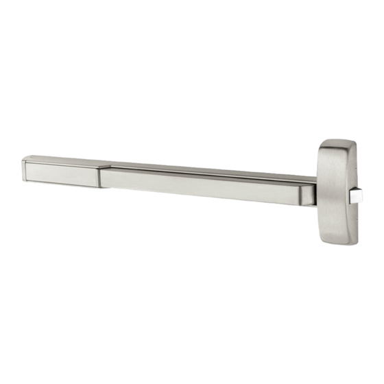
Installation Instructions
FM-PE8700 Series (12- and Standard)
Surface Vertical Rod Exit Devices
WARNING
This product can expose you to
lead which is known to the state of
California to cause cancer and birth
defects or other reproductive harm.
For more information go to www.
P65warnings.ca.gov.
1-800-727-5477 • www.sargentlock.com
Copyright © 2023, SARGENT Manufacturing Company. All rights reserved. Reproduction in whole or in part without the express written
permission of SARGENT Manufacturing Company is prohibited. Patent pending and/or patent www.assaabloydss.com/patents.
WARNING
Attention Installer: Improper
installation may result in damage
to the product and void the factory
warranty.
A8319-1 5/23
Advertisement

Related Manuals for Assa Abloy Sargent FM-PE8700 Series


Summary of Contents for Assa Abloy Sargent FM-PE8700 Series
- Page 1 Installation Instructions FM-PE8700 Series (12- and Standard) Surface Vertical Rod Exit Devices WARNING WARNING This product can expose you to Attention Installer: Improper lead which is known to the state of installation may result in damage California to cause cancer and birth to the product and void the factory defects or other reproductive harm.
- Page 2 FM-PE8700 Series Surface Vertical Rod Exit Device Installation Instructions Screw Chart TOTAL QTY DESCRIPTION WHERE USED SUPPLIED (4) CHASSIS CORNER MOUNTING HOLES #10-24 X 3/4" FLAT HEAD MACHINE SCREW (2) REAR MOUNTING PLATE #10-24 X 3/4" ROUND HEAD SOCKET SCREW (2) CHASSIS TO MOUNT RAIL #8-32 X 3/8"...
- Page 3 FM-PE8700 Series Surface Vertical Rod Exit Device Installation Instructions Screw Chart TOTAL QTY DESCRIPTION WHERE USED SUPPLIED (3) 653 BOTTOM STRIKE 1/4" SLEEVE ANCHOR (2) TOP ROD GUIDE (2) BOTTOM ROD GUIDE #10-24 X 1-1/2" OVAL HEAD MACHINE SCREW (4) CHASSIS COVER (2) END CAP (4) TOP CASE COVER #8-32 X 5/16"...
-
Page 4: Tools Needed
FM-PE8700 Series Surface Vertical Rod Exit Device Installation Instructions Tools Needed Support Block (Provided) Rail Cutting Guide (Provided) Before installation: Note: Please refer to trim and 1. Install mullion, if used. other installation instructions 2. Fit and hang door. provided in the box. 3. -
Page 5: Installation Instructions
FM-PE8700 Series Surface Vertical Rod Exit Device Installation Instructions Product Overview Top strike Interlock Shim Top case Top case cover Rail retainer bolt Rail shim Shim Top rod Shim End Cap Top rod guide Mounting Plate Insert retainer bolt "Lock Down Key" To operate: Depress push rail;... - Page 6 FM-PE8700 Series Surface Vertical Rod Exit Device Installation Instructions • With door closed, measure and mark 2-3/4” • With door closed, tape template for to locate the vertical reference center line of chassis / trim on inside of door, along vertical the chassis, top case, and bottom case.
- Page 7 FM-PE8700 Series Surface Vertical Rod Exit Device Installation Instructions 8 " THRU BOTH SIDES 2X #12-24 TAPPED HOLES THIS SIDE ONLY • Spot and drill all holes from inside of door. • If needed, prepare pockets for outside trim. See installation instructions supplied with trim for details.
- Page 8 FM-PE8700 Series Surface Vertical Rod Exit Device Installation Instructions Frame Cutout 4 " 8 " 2 " 16 " 16 " 16 " (4) #12-24 TAPPED HOLES ALIGN WITH C L OF VERTICAL DOOR STOP ROD EXIT DEVICE RECOMMENDED CUT-OUT IN FRAME FOR 659 TOP BOLT/STRIKE. THIS CUT OUT IS LARGE ENOUGH FOR FUTURE ADJUSTMENT.
- Page 9 FM-PE8700 Series Surface Vertical Rod Exit Device Installation Instructions Mount top strike, (4) #12-24 x 3/4” phillips flat head machine screws. Flat side of top bolt should be facing away from the door. Note: All four fasteners required. DO NOT TIGHTEN FULLY. •...
- Page 10 FM-PE8700 Series Surface Vertical Rod Exit Device Installation Instructions Remove the top case to expose the center hole on the Interlocking shim. Ensure the interlocking shim is aligned with the tracing from Step 6. Mark and tap center hole with #12-24 thread. A8319-1 5/23 1-800-727-5477 •...
- Page 11 FM-PE8700 Series Surface Vertical Rod Exit Device Installation Instructions Attach interlocking shim with (1) #12-24 x 3/4” flat head socket head screw. • Reinstall top case. • Check for top case and top strike engagement. • Tighten all screws. A8319-1 5/23 1-800-727-5477 •...
- Page 12 FM-PE8700 Series Surface Vertical Rod Exit Device Installation Instructions P700 Series ET Trim Chassis P700 Series Trim Position ET trim on door. Align spindle with bell housing. Thru-bolt chassis to ET trim with (2) 1/4-20 flat head screws. Use breaking lines to shorten shim to the needed rail size Refer to rail size listed on the box the device was •...
- Page 13 FM-PE8700 Series Surface Vertical Rod Exit Device Installation Instructions Rail cutting guide If the rail doesn’t need to be cut, continue to page 15 step 13. If the rail must be cut, follow these steps on page 13 and 14: Refer to the individual exit device installation instructions for rail cutting requirements / restrictions.
- Page 14 FM-PE8700 Series Surface Vertical Rod Exit Device Installation Instructions Rail cutting guide, continued. Cut line C. Ensure plastic insert support is installed under D. Wrap the rail and insert in masking tape, the cut line. as shown. Rail Cutting Guide CUT LINE Cut line Place the rail cutting guide over the masking tape and align it with the cut line.
- Page 15 FM-PE8700 Series Surface Vertical Rod Exit Device Installation Instructions Level rail shim on the door and use it as a template. Mark the slot centerlines shown and punch locations for threaded holes where the centerlines intersect. A8319-1 5/23 1-800-727-5477 • www.sargentlock.com Copyright ©...
- Page 16 FM-PE8700 Series Surface Vertical Rod Exit Device Installation Instructions Tracing from Step 13 Remove rail shim from door to expose tracing. Install rail retainer bolt (3/16” wrench). Drill and tap (2) holes as shown in door surface. (“I” drill with 5/16-24 tap for hole at the middle of the door, #7 drill with 1/4-20 tap for hole closer to hinge.
- Page 17 FM-PE8700 Series Surface Vertical Rod Exit Device Installation Instructions Depress chassis lift arm, and slide rail assemby with Install rail insert / shoulder bolt sub-assembly. Do not rail shim onto chassis. Ensure rail retainer bolt engages fully tighten shoulder bolt. properly with slot in rail shim and rail assembly.
- Page 18 FM-PE8700 Series Surface Vertical Rod Exit Device Installation Instructions Verify the rail is level and mark mounting holes, Drill and tap end cap bracket holes #10-24 using the bracket as a guide. (2 Places). Install end cap bracket using round head socket cap Attach rail assembly to chassis with (2) #8 truss #10-24 x 3/4”...
- Page 19 FM-PE8700 Series Surface Vertical Rod Exit Device Installation Instructions • Transfer vertical centerline to threshold. • Align bottom strike. • Mark and drill holes 1-5/8” to 1-3/4” deep for (3) 1/4” sleeve anchors. Note: No clearance in floor is required. Ensure stop is against the door.
- Page 20 FM-PE8700 Series Surface Vertical Rod Exit Device Installation Instructions Using the vertical reference line, with the bottom case as a template, align bottom case as shown. Mark (4) mounting hole locations. 16 " 8 " 16 " • Drill and tap top mounting holes for (2) #12-24 x 3/4” flat head socket screws, using 11/64”...
- Page 21 FM-PE8700 Series Surface Vertical Rod Exit Device Installation Instructions • Install (2) sex nuts from outside door surface. • Install (2) #12-24 x 3/4 socket head cap screws from inside (bottom holes). • Tighten screws with a 1/8” Allen wrench for the top, and 5/32”...
- Page 22 FM-PE8700 Series Surface Vertical Rod Exit Device Installation Instructions • Verify rail is not dogged (locked down). • Slide bottom rod into main slide, center chassis. • Thread bottom rod into bottom case until finger tight. • Adjust position until the center hole is aligned with the bottom slot in the main slide.
- Page 23 FM-PE8700 Series Surface Vertical Rod Exit Device Installation Instructions Drill and tap (2) #10-24 holes per rod guide. Attach rod guides and shims using (2) #10- 24 x 1-1/4” oval head screws per rod guide. A8319-1 5/23 1-800-727-5477 • www.sargentlock.com Copyright ©...
- Page 24 Install all covers using (14) #8-32 x 5/16” screws. Check for proper operation. 1-800-727-5477 • www.sargentlock.com Copyright © 2023, SARGENT Manufacturing Company. All rights reserved. Reproduction in whole or in part without the express written permission of SARGENT Manufacturing Company is prohibited. Patent pending and/or patent www.assaabloydss.com/patents. A8319-1 5/23...
Need help?
Do you have a question about the Sargent FM-PE8700 Series and is the answer not in the manual?
Questions and answers