
Subscribe to Our Youtube Channel
Related Manuals for Chicago Pneumatic CPM 10


Summary of Contents for Chicago Pneumatic CPM 10
- Page 1 Oil-injected rotary screw compressors People. Passion. Performance. CPM 10, CPM 15, CPM 20 Instruction book...
- Page 3 Chicago Pneumatic Oil-injected rotary screw compressors CPM 10, CPM 15, CPM 20 From following serial No. onwards: ITJ 00 00 01 Instruction book Original instructions Copyright notice Any unauthorized use or copying of the contents or any part thereof is prohibited.
-
Page 4: Table Of Contents
Instruction book Table of contents Safety precautions......................5 ........................... 5 AFETY ICONS ......................5 ENERAL SAFETY PRECAUTIONS ................... 6 AFETY PRECAUTIONS DURING INSTALLATION ....................7 AFETY PRECAUTIONS DURING OPERATION ................8 AFETY PRECAUTIONS DURING MAINTENANCE OR REPAIR General description...................... 11 ..........................11 NTRODUCTION ............................ - Page 5 Instruction book 3.10 ......................36 ALLING UP RUNNING HOURS 3.11 ....................... 37 ALLING UP MOTOR STARTS 3.12 .......................37 ALLING UP MODULE HOURS 3.13 ......................38 ALLING UP LOADING HOURS 3.14 ..................... 38 ALLING UP LOAD SOLENOID VALVE 3.15 ..................39 ALLING UP RESETTING THE SERVICE TIMER 3.16 ................
- Page 6 Instruction book ....................59 FILTER AND SEPARATOR CHANGE ......................61 TORAGE AFTER INSTALLATION ..........................61 ERVICE KITS ......................61 ISPOSAL OF USED MATERIAL Adjustments and servicing procedures..............62 ............................62 IR FILTER ............................63 OOLERS ..........................63 AFETY VALVE ....................65 ELT SET EXCHANGE AND TENSIONING Problem solving......................68 Technical data.......................72 ........................
-
Page 7: Safety Precautions
Instruction book Safety precautions Safety icons Explanation Danger to life Warning Important note General safety precautions 1. The operator must employ safe working practices and observe all related work safety requirements and regulations. 2. If any of the following statements does not comply with the applicable legislation, the stricter of the two shall apply. -
Page 8: Safety Precautions During Installation
Instruction book 9. If compressed air is used in the food industry and more specifically for direct food contact, it is recommended, for optimal safety, to use certified Class 0 compressors in combination with appropriate filtration depending on the application. Please contact your customer center for advice on specific filtration. -
Page 9: Safety Precautions During Operation
Instruction book 12. The electrical connections must correspond to the applicable codes. The machines must be earthed and protected against short circuits by fuses in all phases. A lockable power isolating switch must be installed near the compressor. 13. On machines with automatic start/stop system or if the automatic restart function after voltage failure is activated, a sign stating "This machine may start without warning"... -
Page 10: Safety Precautions During Maintenance Or Repair
Instruction book 6. Keep all bodywork doors shut during operation. The doors may be opened for short periods only, e.g. to carry out routine checks. Wear ear protectors when opening a door. On machines without bodywork, wear ear protection in the vicinity of the machine. 7. - Page 11 Instruction book 3. Use only genuine spare parts for maintenance or repair. The manufacturer will disclaim all damage or injuries caused by the use of non-genuine spare parts. 4. All maintenance work shall only be undertaken when the machine has cooled down. 5.
- Page 12 Instruction book Also consult following safety precautions: Safety precautions during installation Safety precautions during operation. These precautions apply to machinery processing or consuming air or inert gas. Processing of any other gas requires additional safety precautions typical to the application which are not included herein. Some precautions are general and cover several machine types and equipment;...
-
Page 13: General Description
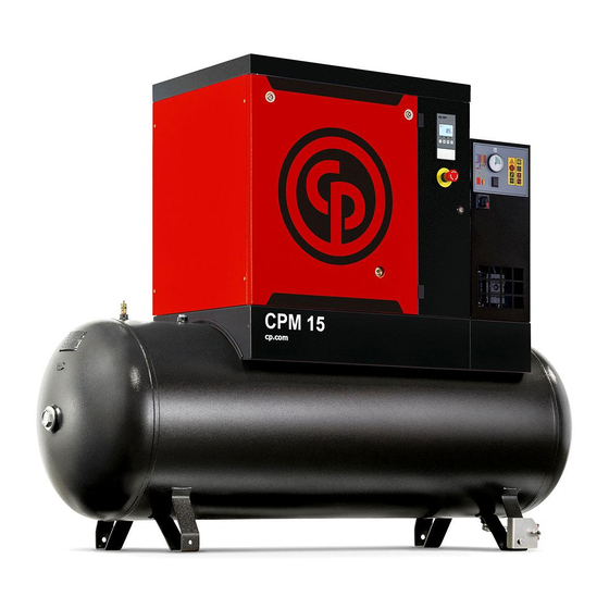
Tank-mounted model CPM 10, CPM 15, CPM 20 tank-mounted are supplied with an air receiver of 270 l (71.28 US gal / 59.40 Imp gal / 9.45 cu.ft) or 500 l (132 US gal / 110 Imp gal / 17.50 cu.ft). - Page 14 Instruction book Reference Designation Emergency stop button Air outlet Air receiver Manual condensate drain Dryer Dewpoint indicator (Only on units with dryer) Front open view, tank-mounted Reference Designation Oil cooler Oil filter Oil separator Oil separator tank 2920 7114 20...
- Page 15 Instruction book Rear open view, tank-mounted Air filter Reference Designation Compressor element Air filter 2920 7114 20...
-
Page 16: Air Flow
Instruction book Air flow Air flow, Tank-mounted Air drawn through filter (AF) and open inlet valve (IV) into compressor element (E) is compressed. Compressed air and oil flow into oil separator/tank (OT). The air is discharged via minimum pressure valve (Vp) towards the air outlet (AO). 2920 7114 20... - Page 17 Instruction book Air flow, Tank-mounted with dryer Air drawn through filter (AF) and open inlet valve (IV) into compressor element (E) is compressed. Compressed air and oil flow into oil separator/tank (OT). The air is discharged via minimum pressure valve (Vp), air receiver (AR) and air dryer (DR) towards the air outlet (AO). 2920 7114 20...
-
Page 18: Oil System
Instruction book Oil system Oil system Oil system, units with dryer 2920 7114 20... -
Page 19: Cooling System
Instruction book Air pressure in the oil separator tank (OT) forces the oil from the tank to compressor element (E) via oil cooler (Co) and oil filter (OF). Compressed air and oil flow into oil separator/tank (OT) where most of the oil is separated from the air by centrifugal action. The remaining oil is removed by oil separator (OS) and returns to the oil circuit via a separate line. -
Page 20: Regulating System
Instruction book Cooling system, units with dryer The cooling system of the version with dryer comprises oil cooler (Co), air receiver (AR) and fan (FN). The dryer (DR) has a separate cooling fan and an automatic condensate drain (see also section dryer). -
Page 21: Control Panel
Instruction book • Unloader (UA), including inlet valve (IV) and unloading valve (UV). • Loading solenoid valve (Y1). • The controller that regulates the compressor based on the pressure settings and readings of the pressure sensor. Loading As long as the working pressure is below the preset maximum, the solenoid valve is energised, allowing control air to the unloader: the inlet valve opens completely and the unloading valve closes completely. -
Page 22: Electrical System
Instruction book Control panel Control panel Reference Designation Electric cabinet ES 4000 Basic Controller Emergency stop button Electrical system Electrical components The electrical system comprises following components: 2920 7114 20... - Page 23 Instruction book Electric cubicle IEC Reference Designation Primary fuse, transformer of the control circuit F2–3 Fuses Motor overload relay Auxiliary circuit relay Delta contactor Line contactor Star contactor Transformer Terminal block of the control circuit Electrical diagram 2205 0126 00 Service diagram IEC The complete electrical diagram can be found in the electric cubicle.
-
Page 24: Protection Of The Compressor
Instruction book Protection of the compressor Safety valve on the compressor and on the vessel Reference Designation Function Safety valve To protect the air outlet system if the outlet pressure exceeds the opening pressure of the valve. 2920 7114 20... -
Page 25: Air Dryer
Instruction book Air dryer Air Dryer Wet compressed air enters the dryer and is further cooled by the outgoing, dried air (2). Moisture in the incoming air condenses. The air then flows through heat exchanger (1) where refrigerant evaporates, withdrawing heat from the air. The cold air then flows through condensate trap (4) which separates condensate from the air. -
Page 26: Controller
Instruction book Controller Controller Control panel Introduction In general, the controller has following functions: • Controlling the compressor; • Protecting the compressor; • Monitoring service intervals; • Automatic restart after voltage failure (made inactive); Automatic control of the compressor The controller maintains the net pressure between programmable limits by automatically loading and unloading the compressor. -
Page 27: Control Panel
Instruction book shutdown warning temperature, this will be indicated on the controller display before the shutdown temperature is reached. Shutdown If the compressor element outlet temperature exceeds the programmed shutdown level or the overload relay of the main motor trips, the compressor will be stopped. This will be indicated on the display of the controller. -
Page 28: Icons Used On The Display
Instruction book Reference Designation Function LED, Voltage on Indicates that the voltage is switched on. Start/stop button Keep pressed for 3 seconds to start compressor. Press to stop compressor if running. Use this button to go to previous screen or to end the current action. -
Page 29: Main Screen
Instruction book Function Icon Description Units Pressure unit (Mega Pascal) Pressure unit (pounds per square inch) Pressure unit (bar) Temperature unit (degree Centigrade) Temperature unit (degree Fahrenheit) Motor A time/delay parameter is displayed. NOTE: • x1000: ON if the displayed value is in thousands of •... -
Page 30: Main Function
Instruction book Main screen with temperature (stopped compressor) Main function To switch on the compressor, press start/stop button (3) for 3 seconds. The compressor starts and the status is shown: Screen with running compressor To stop the compressor, push start/stop button (3). The compressor unloads: Screen with unloading compressor When the unload time is elapsed, the compressor is stopped and the controller goes back to main screen:... - Page 31 Instruction book Main screen with pressure (stopped compressor) To enter the main menu (starting from the Main screen), press the enter button (7) for 3 seconds. The main menu is shown: First screen of main menu It is possible to scroll in the menu with the up or down buttons (4-8). To select one item push the enter button (7).
-
Page 32: Shutdown Warning
Instruction book Alarm reset Shutdown warning Description A shutdown warning will appear in the event of: • A too high temperature at the outlet of the compressor element. Compressor element outlet temperature • If the outlet temperature of the compressor element exceeds the shutdown warning level (factory set at 110˚C/ 230˚F), warning LED (5) is on. -
Page 33: Shutdown
Instruction book It remains possible to check the actual status of other parameters by pressing the enter button (7) for 3 seconds. Press button (3) to stop the compressor and wait until the compressor has stopped. The warning message will disappear as soon as the warning condition disappears. Shutdown Description The compressor will stop:... - Page 34 Instruction book Main screen with shutdown indication, element outlet temperature • The related pictograph will appear flashing. • Scroll Up or Down buttons (4-8) until the current element outlet temperature appears. Shutdown screen, element outlet temperature The screen shows that the temperature at the outlet of the compressor element is 117 ˚C. •...
-
Page 35: Service Warning
Instruction book Main screen with shutdown indication, motor overload • Contact your supplier for fault troubleshooting • When the shutdown condition has been solved, press the enter button (7) for 5 seconds. • When <rSt> appears on the display, the compressor can be restarted. Error pressure/temperature sensor In the event of an error of the outlet pressure sensor (PT20) or temperature sensor (TT11): •... - Page 36 Instruction book Blinking screen • Press Enter button (7) to enter the main menu. • Select <dAtA> and press Enter button (7) to enter the data menu. • Scroll (buttons 4-8) until <d.6> and the service symbol is shown. • Press enter button (7). •...
-
Page 37: Scrolling Through All Screens
Instruction book Scrolling through all screens Control panel General overview of the menu structure From the Main screen press the enter button (7) for 3 seconds to enter the Menu. You will find the following items: dAtA Data counters parameters. ProG Submenu of Regulation pressure, Timer, Display setting and Control setting. -
Page 38: Calling Up Running Hours
Instruction book Overview of the screens Menu item Submenu Digital input screen Designation <dAtA> <d.1> Calling up running hours. (Data) <d.2> Calling up motor starts. <d.3> Calling up module hours. <d.4> Calling up loading hours. <d.5> Calling up load solenoid valve. <d.6>... -
Page 39: Calling Up Motor Starts
Instruction book • Select <dAtA> and press Enter button (7) to enter the Data menu. • Scroll Up or Down buttons (4-8) until <d.1> and the motor stopped symbol is shown. • Press Enter button (7): the running hours are shown. The screen shows the unit used <x1000 hrs>... -
Page 40: Calling Up Loading Hours
Instruction book In the example shown, the screen shows the unit used <hrs> and the value <5000>: the controller module has been in service during 5000 hours. 3.13 Calling up loading hours Starting from the Main screen: • Press Enter button (7) for 3 seconds to enter the Main menu. •... -
Page 41: Calling Up/Resetting The Service Timer
Instruction book This screen shows the number of loading actions (x1 or - if <x1000> lights up - x1000). In the above example, the number of unload to load actions is 10100. 3.15 Calling up/resetting the service timer Starting from the Main screen: •... -
Page 42: Calling Up/Modifying Pressure Band Settings
Instruction book • Scroll Up or Down buttons (4-8) until <PrSL> is shown and then press Enter button (7). • Pressure band 1 (<SEL.1>) is shown. Scroll Up or Down buttons (4–8) to pressure band 2 (<SEL.2>). • Press Enter button (7) on the desired pressure band. 3.17 Calling up/modifying pressure band settings Starting from the Main screen: •... -
Page 43: Calling Up/Modifying The Unit Of Pressure
Instruction book 3.19 Calling up/modifying the unit of pressure The unit of pressure measurement can only be changed when the compressor is stopped. Starting from the Main screen: • Press Enter button (7) for 3 seconds to enter the Main menu. •... -
Page 44: Keyboard Lock
Instruction book 3.22 Keyboard lock Keep both Up and Down buttons pressed for more than 3 seconds to lock or unlock the keyboard. • The display will show the label <Loc> blinking for 3 seconds if the keyboard has been locked. -
Page 45: Installation
Instruction book Installation Installation proposal Outdoor/altitude operation If the compressor is installed outdoors or if the ambient temperature can be below 0˚C (32˚F), precautions must be taken. In this case, and also if operating at high altitude, consult your supplier. Moving/lifting The lifting bars are available as an option. - Page 46 Instruction book Lifting instructions Reference Designation Spacer bars to protect the body. Lifting straps: • Minimum length: 6 meter • ISO 4878 It is recommended to position the lifting straps this way. 2920 7114 20...
- Page 47 Instruction book Installation proposal Installation proposal Ref. Action Main power switch for the compressor (three-phase). Power supply cables need to be protected by suitable conduit. Main power switch for the dryer (single-phase). Power supply cables need to be protected by suitable conduit. Install the compressor on a solid, level floor suitable for taking its weight.
-
Page 48: Dimension Drawings
Instruction book Ref. Action Ventilation: the inlet grids and ventilation fan should be installed in such a way that any recirculation of cooling air to the compressor or dryer is avoided. The air velocity to the grids must be limited to 5 m/s (200 in/s). The required ventilation capacity to limit the temperature of the compressor room can be calculated from the following formula: = 0.92 N / ΔT... -
Page 49: Electrical Connections
Instruction book Electrical connections Always disconnect the power supply before working on the electrical circuit! General instructions Step Action Install an isolating switch near the compressor. Check the fuses and the setting of overload relay. See Settings for overload relay and fuses. - Page 50 Instruction book Ref. Description With all bodywork panels in place, push the start button. • If the sheet is pulled downwards: • Stop the compressor immediately and switch off the voltage. • Reverse two incoming electric lines and repeat the previous step. •...
-
Page 51: Operating Instructions
Instruction book Operating instructions Initial start-up Safety The operator must apply all relevant Safety precautions. General preparation Air receiver port Condensate drain 2920 7114 20... - Page 52 Instruction book Condensate drain valve on air receiver Step Action Consult the installation instructions (see Installation). Check that the electrical connections correspond to the local codes. The installation must be earthed and protected against short circuits by fuses in all phases. An isolating switch must be installed near the compressor.
- Page 53 Instruction book Step Action Check the oil level. The oil level sight-glass (SG) should be between 1/4 and 3/4 full. Start-up Start-up sheet Step Action Affix sheet (5) explaining the procedure for checking the motor rotation direction to the cooling air outlet of the compressor (consult Dimension drawings).
-
Page 54: Starting
Instruction book Starting Automatic drain Condensate drain valve on air receiver Dew point temperature gauge 2920 7114 20... - Page 55 Instruction book Starting the compressor Position of oil sight glass and filler plug Control panel Step Action Before starting, the oil level sight glass (SG) should be between 1/4 and 3/4 full. Switch on the voltage. Open air outlet valve. Push the start button (6).
-
Page 56: Stopping
Instruction book Step Action Regularly check the oil level. 10 to 15 minutes after stopping, the sight glass (SG) should be between 1/4 and 3/4 full. If the oil level is too low, stop the compressor, depressurise the oil system by unscrewing oil filler plug (FC) one turn and wait a few minutes. -
Page 57: Taking Out Of Operation
Instruction book Step Action Push the start/stop button (6) on the controller. The compressor will unload. When the unload time is elapsed, the compressor is stopped and the controller goes back to the main screen. To stop the compressor immediately in the event of an emergency, press button (S3). See section Control panel. - Page 58 Instruction book Oil filler plug This procedure should be carried out at the end of the compressor’s service life. Step Action Stop the compressor and close the air outlet valve . Switch off the voltage and disconnect the compressor from the mains. Depressurise the compressor by opening plug (3) one turn.
-
Page 59: Maintenance
Instruction book Maintenance Preventive maintenance schedule Warning Before carrying out any maintenance, repair work or adjustments, proceed as follows: • Stop the compressor. • Switch off the voltage and open the isolating switch. • Close the air outlet valve and open the manual condensate drain valves. •... -
Page 60: Drive Motor
Instruction book Period (1) Running hours Operation “ “ Have the safety valve tested. “ “ Have the operation of sensors, electrical interlockings and components checked. “ “ Have the temperature shutdown switch tested. “ “ Inspect the air receiver. The air receiver must no longer be used and must be replaced if the wall thickness is less than the minimum value, specified in the technical documentation of the air receiver. -
Page 61: Oil Specifications
Instruction book Oil specifications Never mix oils of different brands or types as they may not be compatible and the oil mix will have inferior properties. A label, indicating the type of oil filled ex-factory, is stuck on the air receiver/oil tank. It is strongly advised to use the recommended lubricants. - Page 62 Instruction book Location of oil filter and separator Step Action Run the compressor until warm. Stop the compressor, close the air outlet valve and switch off the voltage. See Stopping. Depressurise the air receiver by opening drain valve (8). Depressurise the compressor by unscrewing filler plug (2) one turn to permit any pressure in the system to escape.
-
Page 63: Storage After Installation
Instruction book Storage after installation If the compressor is stored without running from time to time, consult your supplier as protective measures may be necessary. Service kits Service kits For overhauling and for preventive maintenance, a wide range of service kits is available. Service kits comprise all parts required for servicing the component and offer the benefits of genuine parts while keeping the maintenance budget low. -
Page 64: Adjustments And Servicing Procedures
Instruction book Adjustments and servicing procedures Air filter Changing the air filter Air filter Procedure: Step Action Stop the compressor, close the air outlet valve and switch off the voltage. Remove the front panel and the top panel of the compressor housing. Unscrew the filter cover (AF) and remove the filter element. -
Page 65: Coolers
Instruction book Coolers Step Action Keep oil cooler (Co) clean to maintain the cooling efficiency. Stop the compressor, close the air outlet valve and switch off the voltage. Remove any dirt from the oil cooler (Co) with a fibre brush. Safety valve Condensate drain valve 2920 7114 20... - Page 66 Instruction book Oil filler plug Testing The valve can be tested on a separate compressed air line. Before removing the safety valve, stop the compressor (see section Stopping), close the air outlet valve, switch off the voltage, open drain valves (4) (tank-mounted units) and the manual drain valve (5) (if fitted - on floor-mounted units) and unscrew filler plug (3) one turn to permit any pressure in the system to escape.
-
Page 67: Belt Set Exchange And Tensioning
Instruction book Belt set exchange and tensioning Read the warning in the Preventive maintenance schedule section. Checking the belt tension Step Action Stop the compressor, close the air outlet valve and switch off the voltage Remove the front door and the internal panel. The force and deflection varies with the power of the unit, and with the total running hours of the belt. - Page 68 Instruction book Tensioning of the belts must be performed with specific dedicated tooling. Adjusting the tension of the drive belts Step Action Stop the compressor, close the air outlet valve and switch off the voltage. Remove the front door, the internal panel, the top cover and the pulley protection. Loosen the 4 bolts (2) by one turn.
- Page 69 Instruction book Replacing the drive belts Step Action The belts (3) must be replaced as a set, even if only one of the belts is worn. Only use genuine belts. Stop the compressor, close the air outlet valve and switch off the voltage. Remove the front door, the internal panel, the top cover, the pulley protection and the left side panel.
-
Page 70: Problem Solving
Instruction book Problem solving Control panel Air outlet valve 2920 7114 20... - Page 71 Instruction book Oil filler plug Condensate drain valve on air receiver 2920 7114 20...
- Page 72 Instruction book Attention Use only authorised parts. Any damage or malfunction caused by the use of unauthorised parts is not covered by Warranty or Product Liability. Apply all relevant Safety precautions during maintenance or repair. Before carrying out any maintenance or repair work on the compressor: push the stop button (6).
- Page 73 Instruction book Condition Fault Remedy Cooler clogged Clean cooler Compressor element (E) out of Consult your supplier order 2920 7114 20...
-
Page 74: Technical Data
Instruction book Technical data Electric cable size Attention The voltage on the compressor terminals must not deviate more than 10% from the nominal voltage. It is however highly recommended to keep the voltage drop over the supply cables at nominal current below 5% of the nominal voltage (IEC 60204-1). If cables are grouped together with other power cables, it may be necessary to use cables of a larger size than those calculated for the standard operating conditions. -
Page 75: Reference Conditions And Limitations
Instruction book Reference conditions and limitations Reference conditions Air inlet pressure (absolute) Air inlet pressure (absolute) 14.5 Air inlet temperature ˚C Air inlet temperature ˚F Relative humidity Working pressure bar(e) Compressor data Working pressure Compressor data Limitations Maximum working pressure bar(e) Compressor data Maximum working pressure... - Page 76 Instruction book Frequency Nominal motor power rating. Dryer power consumption at full load, units with dryer. 0.475 0.474 1.32 1.32 Oil capacity US gal 0.84 Sound pressure level (ISO 2151 - 2004) db(A) 11kW / 15HP 11kW / 15HP Temperature of air leaving outlet valve (ambient +) ˚C approx., tank mounted units.
- Page 77 Instruction book Sound pressure level (ISO 2151 - 2004) db(A) 2920 7114 20...
-
Page 78: Instructions For Use
Instruction book Instructions for use Oil separator vessel The vessel can contain pressurised air. This can be potentially dangerous if the equipment is misused. This vessel must only be used as a compressed air/oil separator tank and must be operated within the limits specified on the data plate. No alterations must be made to this vessel by welding, drilling or other mechanical methods without the written permission of the manufacturer. -
Page 79: Guidelines For Inspection
Instruction book Guidelines for inspection Guidelines On the Declaration of Conformity / Declaration by the Manufacturer, the harmonised and/or other standards that have been used for the design are shown and/or referred to. The Declaration of Conformity / Declaration by the Manufacturer is part of the documentation that is supplied with this compressor. -
Page 80: Pressure Equipment Directives
Instruction book Pressure equipment directives Components subject to 97/23/EC Pressure Equipment Directive Components subject to 97/23/EC Pressure Equipment Directive greater than or equal to category safety valves. See the spare parts book for part numbers. Overall rating The compressors conform to PED smaller than category II. 2920 7114 20... -
Page 81: Declaration Of Conformity
Instruction book Declaration of conformity Typical example of a Declaration of Conformity document (1): Contact address: International Compressor Distribution NV Boomsesteenweg 957 B-2610 Wilrijk (Antwerp) Belgium (2): Applicable directives (3): Standards used On the Declaration of Conformity / Declaration by the Manufacturer, the harmonized and/or other standards that have been used for the design are shown and/or referred to. - Page 84 People. Passion. Performance. www.cp.com...
Need help?
Do you have a question about the CPM 10 and is the answer not in the manual?
Questions and answers