
Related Manuals for Chicago Pneumatic CPF Series


Summary of Contents for Chicago Pneumatic CPF Series
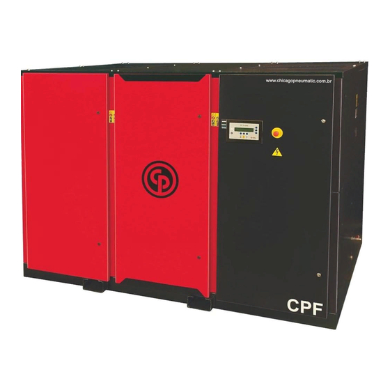
- Page 1 Oil-injected rotary screw compressors People. Passion. Performance. CPF 200-125 460/220V-60Hz - YD BRY190070/UTO-1 BRY190156/ACA-1 Instruction manual...
- Page 2 Compressor Instruction Manual CPF-150, CPF-175, CPF-200 Copyright Statement Any non-authorized use or copy of its contents or any part thereof is prohibited. This refers especially to trademarks, model names, part numbers and data. This manual is valid for compressors with serial number greater than BQD108496. Visit us on: www.chicagopneumatic.com...
- Page 3 STORAGE, CONSERVATION AND TRANSPORT CONDITIONS Introduction Conservation after installation The non-painted surface of all out-of-service compressors, Run the unit at least twice a week, for a minimum of 30 whether installed or waiting installation, is subject to oxidation minutes and operate the load/relief system a few times. and corrosion.
- Page 4 Effectiveness of these warranties is conditioned to immediate written communication of the defect verified by the Buyer to Chicago Pneumatic, and any intervention on the product or equipment by the Buyer or third parties must not be done, under penalty of voiding the warranty.
-
Page 5: Table Of Contents
3.11 Regulation menu ......24 6.3.2 Chicago Pneumatic CP-46 ... 51 3.12 Event history menu . -
Page 6: Safety Precautions
Safety precautions Precautions during installation The machine must only be lifted using suitable 1.1 Safety icons equipment and in accordance with applicable safety regulations. Loose or pivoting parts must be securely Explanation fastened before lifting. It is strictly forbidden to dwell or stay in the risk zone under a lifted load. -
Page 7: Safety Precautions During Operation
The electrical connections must correspond to the must only be performed by authorized, trained and applicable codes. The machines must be earthed and specialized technicians. protected against short circuits by fuses in all phases. A The compressor is not considered capable of producing lockable power isolating switch must be installed near breathable air. -
Page 8: Safety Precautions During Maintenance Or Repair
Precautions during maintenance or repair against air pollution and possible contamination of breathing air. Always wear safety glasses. Do not remove any of or tamper with the sound-damping Use only the correct tools for maintenance and repair material. work. 10. Never remove or tamper with the safety devices, guards Use only genuine spare parts. - Page 9 12. Whenever there is an indication or any suspicion that Also consult following safety precautions: Safety an internal part of a machine is overheated, the machine precautions during operation and Safety precautions shall be stopped but no inspection covers shall be during maintenance.
-
Page 10: General Description
General description 2.1 Introduction CPF-150, CPF-175 and CPF-200 models are single-stage, oil-injected screw, gearbox driven by an electric motor with sound- insulated bodywork. The models with “S” abbreviations are air-cooled, and those with “SW”, water-cooled. The compressors are available for a maximum working pressure of: 7, 8, 10 or 13 bar (e) They essentially feature: •... -
Page 11: Regulating System
2.2 Regulating system Flow diagram Flow diagram Reference Designation To air cooler To/from oil cooler... -
Page 12: Special Features
Regulating system The compressor is controlled by ES4000 controller (1). The controller maintains the net pressure within programmable limits by automatically loading and unloading the compressor, according to the air consumption. It also protects the compressor and monitors components subject to service. Unloading If the air consumption is less than the air output of the compressor, the net pressure increases. -
Page 13: Graphic Controller
Graphic controller Air-cooled compressors will also be stopped in the event of overload of the fan motor. 3.1 Controller Before remedying, consult the Safety precautions. Shutdown warning A shutdown warning level is a programmable level below the shutdown level. If one of the measurements exceeds the programmed shutdown warning level, this will also be indicated to warn the operator before the shutdown level is reached. -
Page 14: Control Panel
3.2 Control panel Detailed description Function keys of the controller Reference Designation Function Function Shows icons and operating conditions. Automatic operation symbol Indicates that the controller is automatically controlling the compressor: the compressor is loaded, unloaded, stopped LED, automatic operation and restarted depending on the air consumption and the limitations programmed in the controller. -
Page 15: Icons Used
3.3 Icons used Status icons Function Icon Function Compressor status When the compressor is stopped, the icon stands still. When the compressor is running, the icon is rotating. Motor stopped Running unloaded Running loaded Machine control mode Local start/stop Remote start/stop LAN control Automatic restart after Automatic restart after voltage failure is active... - Page 16 Main screen view Value lines preview icon Graphic preview icon General icons No communication/network problem Invalid Input icons Icon Description Pressure Temperature Digital input Special protection Input icons Icon Drain Filter Engine Description Compressor element (LP, HP etc.) Dryer Cooler Frequency converter...
- Page 17 Expansion module failed Network problem General alarm Menu icons Icon Description Inputs Outputs Guards (Shutdown warnings) Counters Test Regulation (Settings) Service Event history (saved data) Access key / User password Network Setpoint Information Week timer General...
-
Page 18: Main Screen
Scroll arrows Icon Description Down 3.4 Main screen Function The main screen is the screen automatically displayed when the voltage is switched on and one of the buttons is pressed. It is automatically turned off after a few minutes if no button is pressed. Generally, 5 different main screen views can be chosen: 1. - Page 19 • Section B shows status icons. The following types of icons When Chart (High resolution) is selected, the chart displays are displayed in this field: the variation of the selected input (in this case, the pressure) per minute. The actual value is also displayed. The screen •...
-
Page 20: Accessing Menus
3.5 Accessing menus Procedure On the main screen (see Main Screen): Description • Move the cursor to the Menu button and press the Enter When the voltage is switched on, the main screen automatically button. displays (see Main screen section): •... -
Page 21: Outputs Menu
Selecting another input signal as the main chart signal With the Modify button active (light gray background on the screen above), press Enter on the controller. A screen similar to the following will appear: (1): Set as main chart signal 3.7 Outputs menu Menu icon, Outputs The first item in the list is highlighted. -
Page 22: Counters
Figure text Outputs Fan Motor Blow-off General Shutdown Automatic Operation • The screen displays a list of all outputs, with their respective icons and readings. Figure text If an output is in warning or shutdown, the original icon is replaced, respectively, by the warning or shutdown icon. Counters Running Hours 3.8 Counters... -
Page 23: Service Menu
Press Enter: • Using the scroll buttons, move the cursor to the Service icon (see section below). Three options are available: • Local control • Press the Enter button. The following screen is displayed: • Remote control • LAN control Figure text After selecting the intended control mode, press Enter on the Service... - Page 24 Example of service level (A): Modifying a service plan The numbers shown on the left are the scheduled service Depending on operation conditions, service intervals may intervals. For service interval A, the scheduled number of need to be modified. To do so, use the scroll buttons to select running hours is 4000 hours (top row, green) and the scheduled the value to modify.
-
Page 25: Regulation Menu
History Figure text The History screen lists all past service actions, sorted by Regulation date. The date at the top is the date of the most recent service Unloading pressure 1 action. To see the details of a completed service action (for Loading pressure 1 example, service level, running hours or real time hours), use Unloading pressure 2... -
Page 26: Week Timer Menu
Function • To set timed switching commands for the net pressure range. To access data from last shutdown and last emergency stop. • Four different week schemes can be set. Procedure • A cycle of weeks can be set; one week cycle is a 10-week sequence. - Page 27 • A new warning window will appear. Select an action from this list with the scroll buttons on the controller. Then press Enter to confirm. Week Action Schemes Week Action Scheme 1 Week Action Scheme 2 Monday Week Action Scheme 3 Actions Week Action Scheme 4 Remove...
- Page 28 Monday Start-up Save Modify • A warning window will appear. scroll button or to change the hour value. Use the scroll button or to change the minutes. Monday Are you sure? Save Modify • Press Escape to exit this window. The action is displayed Monday under the day for which it is planned.
- Page 29 Week Cycle Week 1 Week Action Scheme 1 Week Action Scheme 2 Week Action Scheme 3 Modify • Checking the Week Timer status. Use the Escape button on the controller to return to the Week Timer main menu. Select Week Timer status. Week Timer Week Action Schemes Week Cycle...
-
Page 30: Test Menu
Week Timer Week Action Schemes Remaining Running Time 3.14 Test Menu Test Menu Week Timer Week Action Schemes Week Cycle Function Status • To perform a display test, i.e. to check that display and LEDs are still intact. Remaining Running Time Procedure •... -
Page 31: Modification Of General Parameters
3.16 General Menu • The safety valve may only be tested by authorized personnel and must be protected by a safety code. Menu icon, General • Select the display test item and press the Enter button. A screen appears to inspect the display; At the same time, all LEDs are lit. -
Page 32: User Password Menu
• A screen similar to the one above appears with a selection • Select the Activate button and press the Enter button. bar over the first item (Language). Use the navigation • Then complete the User Password and press the Enter button ... -
Page 33: Programmable Parameters
• 1: You can change a basic set of parameters. • 2: You can view and modify additional parameters. • The Access Level can be changed through the Modify button. A warning window will be prompted to enter an Access Key. 3.19 Programmable Parameters Parameters: relief / load pressures Minimum... - Page 34 Assistance Plan The built-in service timer gives a service warning message after a prescheduled time period has elapsed. See also the Maintenance program section. Contact your supplier if a timer parameter needs to be modified. See Access/Modification section of the service timer parameters. Ranges cannot exceed nominal ranges and must logically match.
-
Page 35: Start-Up
3.20 Start-up 3.21 During operation Procedure Notes For the position of the air outlet valve and drain The operator should employ all relevant safety connections, see the Introduction section. precautions. See also the Troubleshooting section. Removing the front panel (service panel) during operation will automatically shut down the unit after a certain period of time, depending on the compressor version. -
Page 36: Automatic Restart
3.23 Stop Checking the oil level Regulator Oil level sight glass position ES 4000 Advanced Control Panel Check the oil level regularly. During operation, the oil level must be between the lower section and center of the sight glass Step Action (Gl). -
Page 37: Removal From Service
3.24 Removal from service Procedure Step Action Stop the compressor and close the air outlet valve. Turn off the power and disconnect the compressor from the power supply. If available, open the condensate drain valve(s) (Dm). Close and depressurize the air network section connected to the outlet valve. -
Page 38: Installation
Installation 4.1 Dimensional drawing Compressor dimensions Dimensional CPF-150... - Page 39 Dimensional CPF-175 and CPF-200...
-
Page 40: Installation Suggestions
Installation suggestions Example of compressor room Example of a compressor room for air refrigerated CPF compressors... - Page 41 (maximum recommended = 0.1 bar) p = Absolute the pressure drop caused by the cooling air outlet pressure at compressor outlet, in bar(a) Qc = ducts. Consult Chicago Pneumatic. Compressor free air throughput, in l/s For British/American units: Remove the plastic plugs (if supplied) from...
-
Page 42: Electric Diagrams
4.3 Electric Diagrams See electrical diagram 1093 1387 35 that is included in the machine CD. 4.4 Cable size, fuses and circuit breaker settings Attention Sizing performed in accordance with NBR 5410 for the following conditions: Local regulations will apply if more stringent than the values proposed below; Insulated conduits or unipolar cables in conduit over the wall;... -
Page 43: Pictographs
4.5 Pictographs Ref. Designation 21 Tightening torques for steel (Fe) or brass (CuZn) screws Automatic condensate drain 22 See Instruction Manual before performing lubrication. Automatic condensate drain for oil/water separator (OSD type) Manual condensate drain 23 Turn off the power before removing the protective cover inside the electrical compartment 24 Lubricate joints, screw the filters and tighten by hand Stop the compressor prior to perform any maintenance... -
Page 44: Operating Instructions
Operating instructions If the compressor has not been used in the last 6 months, it is recommended to increase the 5.1 Initial start lubrication of the compressor element before starting. Fill the compressor element as described The operator should employ all relevant safety in the Oil Change section (paragraph Filling the precautions. -
Page 45: Before Starting
If the direction of rotation of the fan motor is wrong, consult your Chicago Pneumatic Customer Center. Run the compressor for a few minutes and check if it operates normally. -
Page 46: During Operation
5.4 During operation 5.5 Display check Warning Warning The operator should employ all relevant safety Before carrying out any maintenance, repair or precautions. adjustment, stop the compressor, press the emergency stop button and switch off the voltage. Close the air In case of oil leaks inside or outside the machine, outlet valve and open manual condensate drain valve. -
Page 47: Manual Load/Relief
5.6 Manual load/relief 5.7 Stop Control panel Notice After pressing the stop button (11), the compressor operates in relief for 30 seconds. The compressor stops after this time. During this time, a start command is ignored. After stopping, the compressor is prevented from starting within a programmable time (20 seconds). -
Page 48: Removal From Service
5.8 Removal from service Use only the oil specified by the manufacturer. Make sure to completely depressurize the tank Turning off the compressor before opening the drain plug or filler plug. At the end of the compressor operation cycle, proceed as This tank and other pressurized parts are designed follows: and built to ensure an operational life cycle of over 20 years and an infinite number of pressure... -
Page 49: Conservation After Installation
Maintenance 5.10.3 Conservation after installation Run the unit at least twice a week, for a minimum of 30 6.1 Preventive maintenance program minutes and operate the load/relief system a few times. Warning Stop the unit, close the outlet valve and open the condensate drains (after the air cooler and condensate Before any maintenance, repair or adjustment separator manual). - Page 50 List of Tasks for CPF150-200 (CPVS) compressors MAINTENANCE TASKS POINTS PERIOD ACTIVITIES Check work pressure setting Check the oil level and top it up, if needed. Daily Check operation of condensate drains Check temperatures and pressures Check operation of the admission valve Internally and externally clean the unit Externally clean oil and air coolers 2000 hours or...
-
Page 51: Motors
Check the pressure drop when the compressor is running under load and preferably with a stable working pressure. Damaged hoses must be replaced immediately. Service contracts Chicago Pneumatic Customer Centers have a wide range of service contracts tailored to your needs: • An Inspection Plan • A Preventive Maintenance Plan •... -
Page 52: Oil Specifications
6.3.3 CP-46 F Run the compressor until warm. Stop the compressor, Chicago Pneumatic CP-46 F - commonly used in compressors close the air outlet valve and switch off the voltage. applied to food, pharmaceutical and other sector companies. Wait a few minutes and depressurize the system by... -
Page 53: Storage After Installation
Remove the filler plug and fill the air tank with oil until Service kits contain all parts required to service the equipment the level reaches the filler neck. and offer the benefit of genuine Chicago Pneumatic parts, Tighten the filler plug (FC). maintaining lower maintenance costs. All service kits are listed in the corresponding List of Spare Parts. -
Page 54: Troubleshooting
It may be necessary to reset the display after troubleshooting: press the "Reset" (2) key; the message "Todas as Funções de Proteção OK" (All Protection Features OK) will be displayed, and then the compressor can be restarted. Excessive oil consumption Request compressor inspection to the Authorized Chicago Pneumatic Technical Assistance... - Page 55 Condition Problem Solution Request compressor inspection to the Discharge pipe of condensate trap Check and correct, if necessary. Authorized Chicago Pneumatic Technical clogged. Assistance Malfunction of the condensate trip Remove the float assembly, clean and float valves. check. Condition Problem...
-
Page 56: Technical Data
Technical data Data for 7 bar (100 psi) CPF compressors of 60 Hz Units CPF-150 CPF-175 CPF-200 Maximum working pressure, CPF Pack bar(e) Maximum working pressure, CPF Pack psig 107.3 107.3 107.3 Nominal working pressure bar(e) Nominal working pressure psig Motor shaft speed r/min 1780... -
Page 57: Instructions For Using The Air-Oil Separator Vessel
Instructions for using the air-oil separator vessel This vessel may contain pressurized air and may be potentially dangerous if the equipment is misused. It should only be used as an air-oil separator and must be operated within the limits specified on the data plate. No change must be made to the vessel by welding, drilling or other mechanical methods without the written consent of the manufacturer. -
Page 58: Environmental Information
10 Environmental information Check the Environmental Information file recorded on the manual CD provided with the Chicago Pneumatic equipment. This file has guidance on environmental aspects involved in use of Chicago Pneumatic equipment. - Page 59 NOTES...
- Page 60 NOTES...
- Page 61 NOTES...
- Page 62 NOTES...
- Page 63 NOTES...
- Page 64 Chicago Pneumatic Brasil LTDA. Rua São Paulo, 147 - Alphaville Empresarial - Barueri - São Paulo - Brazil Phone: (011) 2189-3900 CNPJ: 51.609.568/0001-45 Visit us on: www.chicagopneumatic.com...
Need help?
Do you have a question about the CPF Series and is the answer not in the manual?
Questions and answers