Table of Contents
Advertisement
"Copyright 2009, Chicago Pneumatic
Any unauthorized use or copying of the contents or any part of this book is
prohibited. This applies in particular to trademarks, model denominations, part
numbers and drawings."
No. 1310 3012 08
2009-06
Chicago Pneumatic Portable Compressor
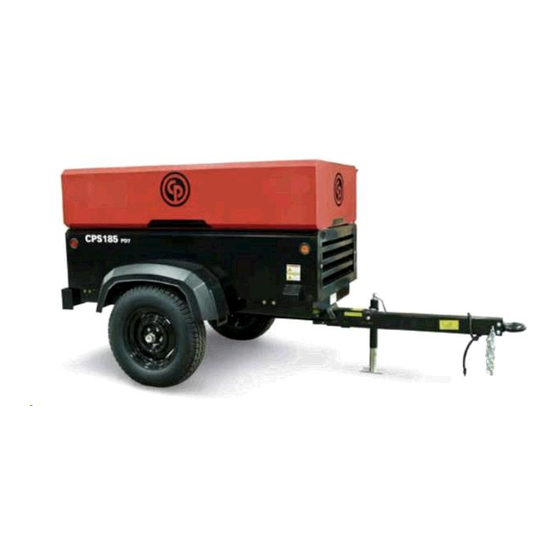
CPS185
PD7
Instruction Book
1310 3012 08 Ed. 0 2009-06
Advertisement
Table of Contents

Related Manuals for Chicago Pneumatic CPS 185 PD7


Summary of Contents for Chicago Pneumatic CPS 185 PD7
- Page 1 Chicago Pneumatic Portable Compressor CPS185 Instruction Book 1310 3012 08 Ed. 0 2009-06 “Copyright 2009, Chicago Pneumatic Any unauthorized use or copying of the contents or any part of this book is prohibited. This applies in particular to trademarks, model denominations, part numbers and drawings.”...
- Page 2 Engine serial no.: Service plan: First start-up date: Selected Lubricants Compressor: Capacity: Printed Matter Nos. Chicago Pneumatic instruction book / rev: Chicago Pneumatic logbook: Chicago Pneumatic parts list / rev: Engine parts list: Local Chicago Pneumatic Representative Name: Address: Telephone:...
-
Page 3: Table Of Contents
Contents Safety Precautions for Portable Compressors Introduction General Safety Precautions Safety during use and operation Safety During Maintenance and Repair Tool Applications Safety Batteries Ether fuel Systems Pressure vessels Safety valve 1.10 Injury Prevention Leading Particulars Description of Safety Pictograms Used in this Manual General Description Main Parts Air Flow (see Fig. -
Page 4: Safety Precautions For Portable Compressors
1.1 Introduction The policy of Chicago Pneumatic is to provide the users of their equipment with safe, reliable and efficient products. Factors taken into account are among others: - the intended and predictable future use of the products, and the environments in which they are expected to operate, - applicable rules, codes and regulations, - the expected useful product life, assuming proper service and maintenance. -
Page 5: Safety During Use And Operation
18 Safety devices shall be tested as described in the maintenance schedule of the instruction book(s) to determine that they are in good operating condition. 19 Never use flammable solvents or carbon tetrachloride for cleaning parts. Take safety precautions against toxic vapors when cleaning parts in or with cleaning products. -
Page 6: Safety During Maintenance And Repair
11 Never move a unit when external lines or hoses are connected to the outlet valves, to avoid damage to valves and/or manifold and hoses. 12 Never refill fuel while the unit is running. Keep fuel away from hot parts such as air outlet pipes or the engine exhaust. Do not smoke when fueling. -
Page 7: Batteries
13 Never use a screwdriver or any other tool near a live wire or electrical component. Plastic covering of handles is for comfort and grip only. They are not intended to act as insulation if such is not clearly marked by the manufacturer. 14 Never strike a hammer against a hardened object;... -
Page 8: Safety Valve
1.9 Safety valve All adjustments or repairs are to be done by an authorized representative of the valve supplier. Following checks must be carried out: A check of the opening of the lifting gear,1 or 2 times a year. This can be done by lifting the ring or lever. A check of the set pressure once a year according to the local regulations, if required. -
Page 9: Leading Particulars
The compressor/engine unit is supported by rubber buffers in the frame. The standard CPS 185 PD7 is equipped with a non-adjustable drawbar with a towing eye and road lighting. As an option, the unit can be equipped with electric or hydraulic braking systems. -
Page 10: Main Parts
2.3 Main Parts AR/OS Fig 2.3 Main parts of CPS 185 PD7 Air Filter Engine Cooling Fan Starter Motor Engine Air Filter Compressor Fuel Filler Cap Oil Cooler Air Receiver Engine Oil Filler Cap Oil Filter Engine Air Outlet Valve... - Page 11 Compressor Regulating System (Load Condition) Fig. 2.4 Compressor Regulating System Air Filter Engine Cooling Fan Regulating Valve Air Filter Compressor Flow Nozzle (Minimum Scavenge Line Air Receiver Pressure) Speed Regulator Air Outlet Valve Compressor Oil Filling Plug Safety Valve BDV Blow Down Valve Flow Restrictor Temperature Switch Compressor Element...
-
Page 12: Air Flow (See Fig. 2.4)
2.4 Air Flow (see Fig. 2.4) The system comprises: Air filter AR/OS Air receiver/oil separator Compressor element UA/UV Unloader assembly with unloader valve Blow-down valve Minimum pressure valve Loading Valve Air drawn through the airfilter (AF) into the compressor element (CE) is compressed. At the element outlet, compressed air and oil pass into the air receiver/oil separator (AR/OS). -
Page 13: Continuous Regulating System
2.6 Continuous regulating system (see Fig. 2.4) The system comprises: Regulating valve Unloader assembly Speed regulator The compressor is provided with a continuous regulating system. This system is provided with a blow-down valve (BDV) which is integrated in the unloader assembly (UA). The valve is closed during operation by outlet pressure of the compressor element and opens by air receiver pressure when the compressor is stopped. -
Page 14: Electrical System
2.7 Electrical System 2.7.1 Circuit Diagram 12V DC 10A F1 P2 + K5 87 K1 86 Temp GENERAL ALARM K2 30 Figure 2.7 Circuit diagram Circuit breaker K3 Relay S4 Lamp test switch Alternator K4 Relay S5 Temperature switch Battery K5 Relay (Compressor) Temperature alarm lamp... - Page 15 2.7.2 Description (see Fig. 2.7) Operation of the electric circuit In detail Start button S1 position 1: Line 2 on 12V contact K3 closed (30-87), lamp H2 is on. K4 excites contact K4 (30-87). Thermocontact element S5 normally closed, K1 excites contact K1 (30-87). Use of preheat: Start button S1 position 1 press pushbutton S8, energizes relay K5 (87-30) and provides power to the glowplug.
-
Page 16: Operating Instructions
3.1.1 Drawbar Preparations for Towing (see Figs. 3.1A-C) Chicago Pneumatic XAS185 compressors may be supplied to a customer with a folded drawbar (see Fig. 3.1A). The drawbar is positioned in it’s upright position for shipping purposes only. When the compressor is received by the end customer, the drawbar will need to be put into it’s operating position. - Page 17 Fig. 3.1B Drawbar Fig. 3.1C Drawbar 3.1.2 Parking Instructions (see Fig. 3.2) When parking a compressor, secure prop (1) or nose wheel to support the compressor in a level position. Place the compressor as level as possible; however, it can be operated temporarily in an out-of-level position not exceeding 15 ° . If the compressor is parked on sloping ground, immobilize the compressor by placing wheel chocks in front of or behind the wheels.
-
Page 18: Before Starting
3.2 Before Starting If the compressor is to be connected to a common compressed air system, fit an appropriate check valve between compressor outlet and air system. Observe the right mounting position/direction! Before initial start-up, prepare battery for operation if not already done. See section 4.7. With the compressor standing level, check the level of the engine oil. -
Page 19: Maintenance
Service Paks include all genuine parts needed for normal maintenance of both compressor and engine. Service Paks minimize downtime and keep your maintenance budget low. You may order Service Paks from your local Chicago Pneumatic dealer. 4.2 Preventive Maintenance Schedule For The Compressor The schedule contains a summary of the maintenance instructions. -
Page 20: Lubrication Oils
Gen Oil M 15W-40 Additional equipment is needed to run the compressor below 18°F. Please contact Chicago Pneumatic for more information about Cold Weather Packages. Operation of compressor in ambient temperatures lower than 18°F (-8°C) without the correct type of oil will void your warranty and may result in element failure and/or fire. -
Page 21: Cleaning Coolers
In this case, contact Chicago Pneumatic. Run the compressor until warm. Close the outlet valve(s) and stop the compressor. Wait until the pressure is released through the automatic blow-down valve. Unscrew the oil filler plug (FP) one turn. This uncovers a vent hole, which permits any pressure in the system to escape. -
Page 22: Storage
If the compressor is going to be stored without running from time to time, protective measures must be taken as described In a separate Service Bulletin (ASB), which may be obtained on request. Consult Chicago Pneumatic. 4.7 Service Kits A service kit is a collection of parts to fit a specific repair or rebuilding task. -
Page 23: Adjustments And Servicing Procedures
Adjustments and Servicing Procedures 5.1 Adjustment of the Continuous Regulating System (See Fig. 5.1) Fig. 5.1 Compressor Regulating System The working pressure is determined by the tension of the spring in the regulating valve (RV). This tension can be increased to raise the pressure and decreased to lower it by turning the adjusting wheel clockwise and counter-clockwise respectively. -
Page 24: Air Filter Engine/Compressor
Vacuator valve 5.2.1.1 Recommendations The Chicago Pneumatic air filters are specially designed for the application. The use of non-genuine air filters may lead to severe damage of engine and/or compressor element. Never run the compressor without air filter element. New elements must also be inspected for tears or punctures before installation. -
Page 25: Air Receiver
Fig. 5.3 Vacuum indicator Air filter contamination indicator Reset button Red indicator 5.3 Air Receiver The air receiver is tested according to official standards. Regularly have inspections carried out in conformity with local regulations. 5.4 Safety Valve All adjustments or repairs are to be done by an authorized representative of the valve supplier. Following checks must be carried out: - a check of the opening of the lifting gear, twice a year. -
Page 26: Problem Solving
Problem Solving 6.1 Problem Solving Chart Use the chart on the following pages to help solve mechanical problems. It is assumed that the engine is in good condition, that there is adequate fuel flow to the filter and injection equipment, and compressor/engine maintained with the recommended oil. - Page 27 Problem Possible faults Corrective actions Discharged or defective Check electrolyte level and charge battery. If no cells are 1. Lamps (H1, H2) do not battery. shorted and battery is discharged, trace cause and light up when switching correct. (S1) to position 1. Loose battery cable(s) or oxidized terminals.
- Page 28 Check the maximum speed, service the Engine does not run at maximum fuel filter. speed. Have element removed and inspected Oil separator element (OS) clogged. by an Chicago Pneumatic Service representative. 12. No air output. Drive coupling broken. Consult Chicago Pneumatic. 13. Pressure rises during See faults 10.
-
Page 29: Technical Specifications
-Relative air humidity Free air delivery is measured according to ISO 1217 ed. 3 1996 annex D which corresponds to American ANSI PTC9. With a tolerance of :+/- 5% 25 l/s<FAD<250 l/s Engine CPS 185 PD7 Make ..........................Perkins Model .......................... - Page 30 Dimensions Overall length (including towbar) in/(mm) ..125/(3200) Overall width in/(mm) ....60/(1524) Overall height in/(mm) ....57/(1448) Gross weight (wet), approximately lb/(kg) ....2400/(1091) Gross weight (dry), approximately lb/(kg) ....2240/(1018) Technical Information Sound pressure level ....................dB(A) at 23ft <76 Wheel nut(s) torque ....................
Need help?
Do you have a question about the CPS 185 PD7 and is the answer not in the manual?
Questions and answers