Table of Contents
Advertisement
Quick Links
Advertisement
Table of Contents

Related Manuals for Chicago Pneumatic CPS 750


Summary of Contents for Chicago Pneumatic CPS 750
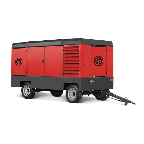
- Page 1 CPS 750 Instruction Manual for Portable Compressors English...
-
Page 3: Instruction Manual
Instruction Manual for Portable Compressors CPS 750 Printed matter N° 1310 3012 02 CHICAGO PNEUMATIC - COMPRESSORS LLC 01/2009... - Page 4 Copyright 2008, Chicago Pneumatic Compressors LLC, RockHill SC USA. Any unauthorized use or copying of the contents or any part thereof is prohibited. This applies in particular to trademarks, model denominations, part numbers and...
-
Page 5: Table Of Contents
Instruction Manual Table of contents SAFETY PRECAUTIONS ..................9 Introduction ....................... 9 General safety precautions ................10 Safety during transport and installation ............... 12 Safety during use and operation ................. 13 Safety during maintenance and repair..............15 Tool applications safety..................16 Specific safety precautions ................ - Page 6 CPS 750 4.6.2 Engine oil ....................52 Oil level check ....................53 4.7.1 Check engine oil level ................... 53 4.7.2 Check compressor oil level ................53 Oil and oil filter change ..................54 4.8.1 Engine oil and oil filter change ............... 54 4.8.2...
- Page 7 Instruction Manual 8.3.4 Design data ....................88 DATAPLATE ....................90 LEGISLATION ....................91 10.1 Parts, subjected to Pressure Equipment Directive 97/23/EC, cat. II and above ..91 10.2 Parts, subjected to Simple Pressure Vessel Directive87/404/EC......91 10.3 Parts, subjected to cat. I and covered by the Machine Directive 89/392/EC ..... 91 10.4 Parts, subjected to art.
- Page 8 CPS 750 1310 3012 02...
-
Page 9: Safety Precautions
Introduction The policy of Chicago Pneumatic is to provide the users of their equipment with safe, reliable and efficient products. Factors taken into account are among others: • the intended and predictable future use of the products, and the environments in which they are expected to operate, •... -
Page 10: General Safety Precautions
Chicago Pneumatic. The manufacturer does not accept any liability for any damage arising from the use of non-original parts and for modifications, additions or conversions made without the manufacturer’s approval in writing. - Page 11 Instruction Manual The supervisor, or the responsible person, shall at all times make sure that all instructions regarding machinery and equipment operation and maintenance are strictly followed and that the machines with all accessories and safety devices, as well as the consuming devices, are in good repair, free of abnormal wear or abuse, and are not tampered with.
-
Page 12: Safety During Transport And Installation
CPS 750 Safety during transport and installation To lift a unit, all loose or pivoting parts, e.g. doors and towbar, shall first be securely fastened. Do not attach cables, chains or ropes directly to the lifting eye; apply a crane hook or lifting shackle meeting local safety regulations. -
Page 13: Safety During Use And Operation
12 Never remove a filler cap of the cooling water system of a hot engine. Wait until the engine has sufficiently cooled down. 13 Never refill fuel while the unit is running, unless otherwise stated in the Chicago Pneumatic Instruction Book (AIB). Keep fuel away from hot parts such as air outlet pipes or the engine exhaust. - Page 14 CPS 750 14 All doors shall be shut during operation so as not to disturb the cooling air flow inside the bodywork and/or render the silencing less effective. A door should be kept open for a short period only e.g. for inspection or adjustment.
-
Page 15: Safety During Maintenance And Repair
If any sound-damping material is damaged, replace it to prevent the sound pressure level from increasing. 14 Use only lubricating oils and greases recommended or approved by Chicago Pneumatic or the machine manufacturer. Ascertain that the selected lubricants comply with all applicable safety regulations, especially with regard to explosion or fire-risk and the possibility of decomposition or generation of hazardous gases. -
Page 16: Tool Applications Safety
CPS 750 18 Disconnect –battery-clamp before starting electrical servicing or welding (evt. turn battery-switch in “off” position). 19 When repair has been completed, the machine shall be barred over at least one revolution for reciprocating machines, several revolutions for rotary ones to ensure that there is no mechanical interference within the machine or driver. - Page 17 Instruction Manual Pressure vessels (according to directive 87/404/EEC annex II § 2) Maintenance/installation requirements: The vessel can be used as pressure vessel or as separator and is designed to hold compressed air for the following application: • pressure vessel for compressor, •...
-
Page 18: Leading Particulars
CPS 750 Leading particulars General description The CPS 750 is a silenced, single-stage, oil-injected screw compressor, built for a nominal effective working pressure of 7.0 bar (102 psi). • Engine The compressor is driven by a liquid-cooled diesel engine. The engine’s power is transmitted to the compressor element through a heavy-duty coupling. - Page 19 Instruction Manual • Toolbox For the basic unit the max. allowed weight in the toolbox is 90 kg (198 lb). For the full option unit (incl. aftercooler, reheater, etc.) the max. allowed weight in the toolbox is 20 kg (44 lb). •...
-
Page 20: Markings And Information Labels
CPS 750 Markings and information labels Dangerous outlet gases. Danger, heat flat. Electrocution hazard. Chicago Pneumatic mineral compressor oil. Chicago Pneumatic synthetic compressor oil. Chicago Pneumatic mineral engine oil. Manual. Read the instruction manual before working on the battery. Reset fuse. - Page 21 Instruction Manual Service every 24 hours. Warning! Part under pressure. Do not stand on outlet valves. Start-Stop indication of switch. Do not run the compressor with open doors. Lifting permitted. Use diesel fuel only. 5.75 bar Tyre pressure. (83 psi) Sound power level in accordance with Directive 2000/14/EEC (expressed in dB (A)).
-
Page 22: Main Parts
CPS 750 Main parts Reference Name Alternator AFce Air Filter (compressor element) Air Filter (engine) Air Filter Sensor Air Outlet Valves Air Receiver Battery Circuit Breaker Compressor Element Control Panel Coolant Tank Control Unit Data Plate 1310 3012 02... - Page 23 Instruction Manual Reference Name DPeo Drain Plug Engine Oil DPoc Drain Plug Oil Cooler Drain Plug Radiator Engine Oil Level Dipstick Engine Exhaust Pipe Emergency Stop FCeo Filler Cap (engine oil) FCft Filler Cap (fuel tank) Filler Cap (coolant) Fuel Filter Caterpillar FFpc Fuel Prefilter Caterpillar Fuel Level Gauge...
-
Page 24: Regulating System
CPS 750 Regulating system 2.4.1 Overview Reference Name AFce Air Filter (compr. element) Air Filter (engine) Air Filter Sensor Air Outlet Valves Air Receiver Breather Nozzle Blow Off Valve BVof By-pass Valve (oil filter) 1310 3012 02... - Page 25 Instruction Manual Reference Name Coupling Compressor Element Check Valve DPar Drain Plug (air receiver) DPcv Drain Plug (check valve) DPosv Drain Plug (oil stop valve) Engine FPco Filler Plug (oil compressor element) Flow Restrictor Loading Valve Minimum Pressure Valve Oil Cooler OFce Oil Filter (compressor element) Oil Level Gauge...
-
Page 26: Air Flow
CPS 750 2.4.2 Air flow Air drawn through the airfilter (AFce) into the compressor element (CE) is compressed. At the element outlet, compressed air and oil pass into the air receiver/oil separator (AR/OS). The check valve (CV) prevents blow-back of compressed air when the compressor is stopped. In the air receiver/oil separator (AR/OS), most of the oil is removed from the air/oil mixture;... -
Page 27: Oil System
Instruction Manual 2.4.3 Oil system The lower part of the air receiver (AR) serves as oil tank. Air pressure forces the oil from the air receiver/oil separator (AR/OS) through the oil cooler (OC), the oil filters (OFce) and the oil stop valve (OSV) to the compressor element (CE). When the compressor is stopped and / or there is no pressure in the system, the oil stop valve (OSV) prevents the oil from flowing back into the compressor element. -
Page 28: Continuous Regulating System
CPS 750 2.4.4 Continuous regulating system The compressor is provided with a continuous regulating system and a blow-off valve (BOV) which is integrated in the unloader assembly (UA). The valve is closed during operation by outlet pressure of the compressor element and opens by air receiver pressure when the compressor is stopped. - Page 29 Instruction Manual If the air consumption is equal to or exceeds the maximum air output, the engine speed is held at maximum load speed and the throttle valve (TV) is fully open. If the air consumption is less than the maximum air output, air receiver pressure increases and the regulating valve supplies control air to throttle valve (TV) to reduce the air output and holds air receiver pressure between the normal working pressure and the corresponding unloading pressure.
-
Page 30: Electric System
CPS 750 Electric system Circuit diagram (9822 0937 15) J3/P3-8 J3/P3-7 J3/P3-40 J3/P3-20 J3/P3-21 J3/P3-22 24VDC J3/P3-9 1310 3012 02... - Page 31 Instruction Manual C1Spare I/O (female contacts) D1Diode F1Fuse 15A F2Fuse 100A G1Battery G2Battery G3Alternator K0Relay Starter motor K1Relay, Aux. Starter K2Relay, Air inlet heater V+ 5VDC LS1Level Switch, Coolant level V+ 24VDC LT1Level sensor (capacitive), Fuel level M1Starter motor N1Compressor Control Module V+ 5VDC V+ 24VDC N2Engine Control Module (Caterpillar)
-
Page 32: Operating Instructions
CPS 750 Operating instructions Parking, towing and lifting instructions Safety precautions The operator is expected to apply all relevant 1 Safety precautions. Attention • Before putting the compressor in to use, check the brake system as described in section 5.5.1 Brake shoe adjustment. -
Page 33: Parking Instructions
Instruction Manual 3.1.1 Parking instructions When parking a compressor, secure the jockey wheel (1) to support the compressor in a level position. Place the compressor as level as possible; however, it can be operated temporarily in an out-of-level position not exceeding 15°. If the compressor is parked on sloping ground, immobilize the compressor by placing wheel chocks (available as option) in front of or behind the wheels.. -
Page 34: Towing Instructions
CPS 750 3.1.2 Towing instructions Label on towbar, towing instructions Before towing the compressor, ensure that the towing equipment of the vehicle matches the towing eye or ball connector. The towbar should be as level as possible and the compressor and towing eye end in a level position. -
Page 35: Lifting Instructions
Instruction Manual 3.1.3 Lifting instructions Lifting eye When lifting the compressor, the hoist has to be placed in such a way that the compressor, which must be placed level, will be lifted vertically. Keep lifting acceleration and retardation within safe limits. Preferably use the lifting eye (1) after opening the small door (2). -
Page 36: Before Starting
CPS 750 Before starting Step Action Before initial start-up, prepare battery for operation if not already done. See section 4.13.3 Recharging a battery. With the compressor standing level, check the level of the engine oil. Add oil, if necessary, to the upper mark on dipstick. Also check the engine coolant level. -
Page 37: Starting / Stopping
Instruction Manual Starting / Stopping Safety precautions Do not disconnect power supply to control box in any way when the control box is switched on. This will cause memory loss. Do not switch off the circuit breaker when the control box is switched on. This will cause memory loss. -
Page 38: Control Panel
CPS 750 3.3.1 Control panel Control panel Reference Name Emergency stop Display (2 rows, 40 characters / row) Pressure gauge Fuel level gauge LOAD Load-Noload button Stop button Start button ON/OFF Power ON/OFF switch 1310 3012 02... -
Page 39: During Operation
Instruction Manual 3.3.2 During operation The doors must be closed during operation and may be opened for short periods only. Regularly carry out following checks: That the regulating valve (RV) is correctly adjusted, i.e. starts decreasing the engine speed when reaching the preset working pressure in the receiver. -
Page 40: Power On/Off
CPS 750 3.3.3 Power ON/OFF Switch the machine on by switching the “ON/OFF” switch to the position “ON”. The instrument panel will now perform a brief selftest. The display will show: The machine is ready for starting. The operator can modify certain settings by pressing and holding the button “0”, and pressing the button “LOAD”. -
Page 41: Starting
Instruction Manual Use the buttons “I” and “0” to scroll upwards and downwards respectively. Press the button “LOAD” to enter a menu or to confirm a new parameter setting. The down-arrow on the left hand indicates that the operator can scroll downwards. Pressing the button “LOAD”... -
Page 42: Warming Up
CPS 750 A starting attempt will last 60 seconds max. To cool down the starting motor, the system will wait 1 minute max. before undertaking the next attempt, meanwhile do not leave the compressor. Press the button “0” to prevent the system from undertaking any starting attempts after the first or second starting attempt. -
Page 43: Loading
Instruction Manual The warm-up time setting is 5 minutes max. There will be no warming up if the coolant temperature has already reached 40 °C (104 °F). The display will show: After warming up the engine will run idle at an air receiver pressure of approx. 2 bar (29 psi). The engine rpm is shown on the display. -
Page 44: Stopping
CPS 750 The display will show: If the button “LOAD” is pressed after warming up, the compressor immediately will enter the load status. The pressure will rise till it reaches the setting. The engine rpm is shown on the display. The status is indicated as UNLOAD when the valves are shut. -
Page 45: Shut Downs
Instruction Manual The remaining time is shown in the display: Meanwhile the air receiver is depressurised. Switch the “ON/OFF” switch to the position “OFF”. Do not push Emergency Stop during cool down process. 3.3.8 Shut downs There are several parameters that are continuously watched. When one of these parameters exceeds its specified limit the compressor will shut down immediately. -
Page 46: Emergency Stop
CPS 750 3.3.9 Emergency stop In case of an emergency, pressing the red emergency button immediately stops the machine. By turning the emergency button, the system is reset. The display shows: 3.3.10 Warnings A warning will be generated when: • Air filters: The air filters need cleaning. -
Page 47: Maintenance
Service Paks include all genuine parts needed for normal maintenance of both compressor and engine. Service Paks minimize downtime and keep your maintenance budget low. Order Service Paks at your local Chicago Pneumatic dealer. Service kits A service kit is a collection of parts to fit a specific repair or rebuilding task. -
Page 48: Storage
CPS 750 Storage Run the compressor regularly, e.g. twice a week, until warm. Load and unload the compressor a few times to operate the unloading and regulating components. Close the air outlet valves after stopping. If the compressor is going to be stored without running from time to time, protective measures must be taken. - Page 49 50 hours after Every 6 months Yearly or every initial start-up or every 500 1000 hours hours supplied with Service pak CPS 750 unit 1310 3126 07 1310 3126 08 Engine oil level Check Compressor oil level Check Coolant level...
- Page 50 500 hours is only valid when using GENOIL 15W40. Check additive concentration every 500 h. Change coolant every 1000 h. Use Chicago Pneumatic oil filters, with by-pass valve, as specified in the parts list. Replace the fuel filters regularly. Gummed or clogged filters mean fuel starvation and reduced engine performance.
-
Page 51: Oil Specifications
Instruction Manual Oil specifications It is strongly recommended to use Chicago Pneumatic branded lubrication oils for both compressor and engine. High-quality, mineral, hydraulic or synthesized hydrocarbon oil with rust and oxidation inhibitors, anti- foam and anti-wear properties is recommended. The viscosity grade should correspond to the ambient temperature and ISO 3448, as follows:... -
Page 52: Engine Oil
CPS 750 4.6.2 Engine oil GENOIL from Chicago Pneumatic is the ONLY oil tested and approved for use in all engines built into Chicago Pneumatic compressors and generators. Extensive laboratory and field endurance tests on Chicago Pneumatic equipment have proven GENOIL to match all lubrication demands in varied conditions. -
Page 53: Oil Level Check
Instruction Manual Oil level check 4.7.1 Check engine oil level Also consult the Engine Operation Manual for the oil specifications, viscosity recommendations and oil change intervals. For intervals, see 4.5 Preventive maintenance schedule for the compressor. Check engine oil level according to the instructions in the Engine Operation Manual and if necessary top up with oil. -
Page 54: Oil And Oil Filter Change
When operating in high ambient temperatures, in very dusty or high humidity conditions, it is recommended to change the oil more frequently. In this case, contact Chicago Pneumatic Oil filters Run the compressor until warm. Close the outlet valve(s) (1) and stop the compressor. -
Page 55: Topping Up The Compressor Oil
Instruction Manual Clean the filter seat on the manifold, taking care that no dirt drops into the system. Oil the gasket of the new filter element. Screw it into place until the gasket contacts its seat, then tighten one half turn only. Fill the air receiver until the pointer of the oil level gauge is in the upper part of the green area. -
Page 56: Coolant Specifications
A sudden release of pressure from a heated cooling system can result in personal injury from the splash of hot coolant. It is strongly recommended to use Chicago Pneumatic branded coolant. The use of the correct coolant is important for good heat transfer and protection of liquid-cooled engines. -
Page 57: Gencool Eg
Chicago Pneumatic compressors and generators. Chicago Pneumatic's GENCOOL EG extended life coolant is the new range of organic coolants purpose designed to meet the needs of modern engines. GENCOOL EG can help prevent leaks caused by corrosion. -
Page 58: Handling Gencool Eg
CPS 750 4.9.2 Handling GENCOOL EG GENCOOL EG should be stored at ambient temperatures, while periods of exposure to temperatures above 35°C (95°F) should be minimized. GENCOOL EG can be stored for a minimum of 5 years in unopened containers without any effect on the product quality of performance. -
Page 59: Coolant Check
• Check the pH value of the coolant using a pH-measuring device. • The pH-meter can be ordered from Chicago Pneumatic with part number 2913 0029 00. • Typical value for EG = 8.6. • If the pH-level is below 7 or above 9.5, the coolant should be replaced. -
Page 60: Topping Up/Replacing Coolant
CPS 750 4.11 Topping up/replacing coolant • Verify if the engine cooling system is in a good condition (no leaks, clean,...). • Check the condition of the coolant. • If the condition of the coolant is outside the limits, the complete coolant should be replaced (see section 4.11.3 Replacing the coolant). -
Page 61: Topping Up Without Draining From The Cooling System
Instruction Manual 4.11.1 Topping up without draining from the cooling system The quantity of GENCOOL EG Concentrate to be topped up can be estimated with the following formula and/or graph: Corrections concentrate in measured system towards 50% volume by using GENCOOL EG Concentrate PN: 1626 2257 00 Example: Total volume coolant =... -
Page 62: Topping Up After Limited Quantity Draining From The Cooling System
CPS 750 4.11.2 Topping up after limited quantity draining from the cooling system The quantity of GENCOOL EG Concentrate to be topped up after draining a calculated volume from the cooling system, can be estimated with the following formula and/or graph:... -
Page 63: Replacing The Coolant
• Flush twice with clean water. Used coolant must be disposed or recycled in accordance with laws and local regulations. • From the Chicago Pneumatic Instruction book, determine the amount of GENCOOL EG required and pour into the radiator top tank. -
Page 64: Cleaning Coolers
CPS 750 4.12 Cleaning coolers Compressor oil cooler (1) and engine liquid cooler (2) and intercooler (3) Keep the coolers (1), (2) and (3) clean to maintain the cooling efficiency. Remove any dirt from the coolers with a fibre brush. Never use a wire brush or metal objects. -
Page 65: Electrolyte
Instruction Manual 4.13.1 Electrolyte Read the safety instructions carefully. Electrolyte in batteries is a sulphuric acid solution in distilled water. The solution must be made up before being introduced into the battery. Always pour the sulphuric acid carefully into the distilled water; never pour the water into the acid. -
Page 66: Adjustments And Servicing Procedures
CPS 750 Adjustments and servicing procedures Adjustment of the continuous regulating system The working pressure is determined by the tension of the spring in the regulating valve (RV). This tension can be increased to raise the pressure and decreased to lower it by turning the adjusting wheel clockwise and anti-clockwise respectively. -
Page 67: Air Filters Engine / Compressor
Dust trap cover Safety cartridge Filter element Filter housing Vacuator valve The Chicago Pneumatic air filters are specially designed for the application. The use of non-genuine air filters may lead to severe damage of the engine and/or compressor elements. 1310 3012 02... -
Page 68: Cleaning The Dust Trap
CPS 750 5.2.2 Cleaning the dust trap Air filter To remove dust from the dust trap pinch the vacuator valve (1) several times. 5.2.3 Replacing the filter element and the safety cartridge Air filter The instructions apply to one air filter and should be repeated for both air filters engine and air filters compressor. -
Page 69: Air Receiver
Instruction Manual Step Action Discard the filter element when damaged. A dirty safety cartridge (3) is an indication of a malfunctioning filter element. Replace the filter element and the safety cartridge at the same time. New elements should be inspected for tears and punctures before installation. The safety cartridge cannot be cleaned. -
Page 70: Fuel System
CPS 750 Fuel system 5.3.1 Fuel system - Drain Fuel filter Fuel Pre-filter Step Action Open bowl drain valve (1), operate pump (2) and pump water out. Close drain valve (1). 1310 3012 02... -
Page 71: Fuel System - Prime
Instruction Manual 5.3.2 Fuel system - Prime Fuel leaked or spilled onto hot surfaces or electrical components can cause a fire. To help prevent possible injury, turn the “ON/OFF” switch in position “OFF” when changing fuel filters or water separator elements. Clean up fuel spills immediately. Prime the fuel system in order to fill the fuel filter. - Page 72 CPS 750 • Switch the “ON/OFF” switch to position ”ON”. The instrument panel will now perform a brief selftest. See section 3.3.3 Power ON/OFF. • Push the start button and the starter motor will automatically try to start the engine, see section 3.3.4 Starting.
-
Page 73: Replacing Filter Elements
Instruction Manual 5.3.3 Replacing filter elements Fuel filter AC Fuel Pre-filter Step Action Drain fuel from the bowl. Remove filterelement (2) and separate bowl (1) from element. Apply film of gas oil to bowl seat. Screw bowl (1) to new element (2) tightly by hand. Apply film of gas oil to new element seal. -
Page 74: Safety Valve
CPS 750 Safety valve All adjustments or repairs are to be done by an authorized representative of the valve supplier. Following checks must be carried out: • A check of the opening of the lifting gear, twice a year. This can be done by screwing the cap of the valve anti-clockwise. -
Page 75: Brake Adjustment
Instruction Manual Brake adjustment Before jacking up the compressor, connect it to a towing vehicle or attach a weight of minimum 50 kg (110 lb) to the towbar. 5.5.1 Brake shoe adjustment Brake shoe adjustment Check the thickness of the brake lining. •... - Page 76 CPS 750 Brake shoe adjustment re-establishes the brake lining-to-drum clearance and compensates for lining wear. Step Action Lift and support the compressor. Make sure that all brakes (overrunbrake and hand brake) are off. The brake cables must be free from tension.
-
Page 77: Problem Solving
If air leaks from the hose, remove and inspect loading valve. Replace damaged or worn O-rings. Oil separator element clogged. Have element removed and inspected by an Chicago Pneumatic Service representative. Air intake throttle valve remains partially Remove air filters, air intake manifold and closed. - Page 78 CPS 750 Problem: Pressure in air receiver rises above maximum and causes safety valve to blow. Possible faults Corrective actions Regulating valve (RV) opens too late or its Dismantle and inspect parts. ball valve spring is broken. Air leaks in regulating system.
- Page 79 Oil stop valve malfunctioning. Remove and inspect valve. Oil separator element (OS) clogged. Have element removed and inspected by an Chicago Pneumatic Service representative. Alternator precautions Never reverse the polarity of the battery or the alternator. Never break any alternator or battery connections while the engine is running.
-
Page 80: Available Options
CPS 750 Available options Support A rigid support mounted version for rough construction conditions with the possibility to be mounted on a truck. The installation allows the unit to be put on and taken off the truck daily. It is possible to handle the unit with a forklift. - Page 81 Instruction Manual Reheater For applications with a need for dry unsaturated air or where ambient conditions cause risk of freezing tools a reheater can be installed. The reheater can only be installed in combination with the after cooler pack and will increase air discharge temperature close to a+60°C. Spark arrestor The spark arrestor option prevents burning particles leaving the exhaust system.
-
Page 82: Technical Specifications
CPS 750 Technical specifications Torque values 8.1.1 For general applications Torque values The following tables list the recommended torques applied for general applications at assembly of the compressor. For hexagon screws and nuts with strength grade 8.8 Thread size Torque value (Nm) Torque value (lbf.ft) -
Page 83: For Important Assemblies
Instruction Manual 8.1.2 For important assemblies Assemblies Torque value (Nm) Torque value (lbf.ft) Wheel nuts 200-290 148-214 Bolts, axle/bottom 80 +/- 10 59 +/- 7 Bolts, towbar/beams 205 +/- 20 151.29 +/- 15 Bolts, towing eye/towbar 80-90 59-66 Bolts, lifting eye/beams 205 +20 151.29 +15 Bolts, engine/drive housing (M12) -
Page 84: Settings Of Shutdown Switches And Safety Valves
CPS 750 Settings of shutdown switches and safety valves Settings Designation CPS 750 Engine oil pressure bar(e) Engine coolant temperature °C °F Compressor temperature °C °F Safety valve opening pressure: - EC type bar(e) 13.5 Safety valve opening pressure: - ASME type bar(e) 14.1... -
Page 85: Limitations
Instruction Manual 8.3.2 Limitations Designation CPS 750 Minimum effective receiver pressure bar(e) Maximum effective receiver pressure, bar(e) compressor unloaded Maximum ambient temperature at sea level °C °F Minimum starting temperature °C °F Minimum starting temperature, with coldstart °C equipment °F... - Page 86 CPS 750 1310 3012 02...
-
Page 87: Performance Data
Instruction Manual 8.3.3 Performance data At reference conditions, if applicable, and at normal shaft speed, unless otherwise stated. Designation CPS 750 Engine shaft speed, normal and r/min 2100 maximum Engine shaft speed, compressor r/min 1300 unloaded Free air delivery US gal/s 91.1... -
Page 88: Design Data
CPS 750 8.3.4 Design data Compressor element Designation Number of compression stages Engine Designation CPS 750 Make Caterpillar Type C6.6 ACERT Coolant Liquid Number of cylinders Bore 4.13 Stroke 4.95 Swept volume US gal 1.74 Imp gal 1.45 cu.in Output according to SAE J1995 at normal shaft speed 195.8... - Page 89 Instruction Manual Compressor Designation CPS 750 Capacity of compressor oil system US gal 12.9 Imp gal 10.8 cu.ft Net capacity of air receiver 63.5 US gal 16.8 Imp gal cu.ft Capacity of fuel tanks US gal 76.3 Imp gal 63.6 cu.ft...
-
Page 90: Dataplate
CPS 750 Dataplate 1310 3012 02... -
Page 91: Legislation
Instruction Manual Legislation 10.1 Parts, subjected to Pressure Equipment Directive 97/23/EC, cat. II and above Safety valve: cat. IV Designation CPS 750 Set pressure: - EC type bar(e) 13.5 Set pressure: - ASME type bar(e) 14.1 Design temperature °C °F 10.2... - Page 92 CPS 750 1310 3012 02...
Need help?
Do you have a question about the CPS 750 and is the answer not in the manual?
Questions and answers