Table of Contents
Advertisement
Quick Links
Advertisement
Table of Contents

Related Manuals for Spectra MKS-11


Summary of Contents for Spectra MKS-11
- Page 1 MKS-11 “SPECTRA” SEARCH DOSIMETER-RADIOMETER Operating Manual...
-
Page 3: Table Of Contents
CONTENTS 1 DESCRIPTION AND OPERATION .......... 3 1.1 P ..............3 URPOSE OF USE 1.2 T ..........4 ECHNICAL SPECIFICATIONS 1.3 D ..........12 ELIVERY KIT OF THE DEVICE 1.4 D ........ 13 ESIGN AND PRINCIPLE OF OPERATION 1.5 L ............ - Page 4 The MKS-11 “SPECTRA” search dosimeter-radiometer is designed in the following modifications: - MKS-11 G “SPECTRA” is designed to measure the ambient dose equivalent rate of gamma radiation and X-rays, the ambient dose equivalent of gamma radiation and X-rays, and identify gamma radionuclides by their amplitude spectra;...
-
Page 5: Description And Operation
• Identify the type of radionuclides by their amplitude gamma spectra; • Store amplitude gamma spectra and events in the nonvolatile memory. The device is designed under ANSI N42.48-2008. The device is used to detect and localize radioactive and nuclear... -
Page 6: Technical Specifications
1.2 Technical specifications 1.2.1 Key specifications are presented in Table 1.1. Table 1.1 Measure- Name ment Standardized value unit Total measurement and 0.01…10 display range of photon- ionizing DER: μSv/h From built-in: 0.01 to 50 -SGDU 50 to 10 -GMC Measurement and display μSv 0.1…9.9·10... - Page 7 Table 1.1 (continued) Measure- Standardized Name ment unit value Main relative permissible error limit when measuring photon- ionizing radiation DER and DE from the GMC at 0.95 confidence probability ( Energy range of detected 0.02 … 3.00 photon-ionizing radiation Energy dependence of the device’s readings when measuring photon-ionizing ±25...
- Page 8 Table 1.1 (continued) Measure Standardized Name ment value unit Calibration time by the level 2 … 90 of gamma background Response time to over 10 times change of photon- 0.25 ionizing radiation DER Operating supply voltage of the device from a lithium- polymer battery Continuous operation of the device when powered from the...
- Page 9 1.2.2 The photon-ionizing radiation sensitivity of ( Cs) CsI(Tl) scintillation detector is at least 400 (cps)/(µSv/h). Note. At the request of the user, the sensitivity can be changed to a value of not less than 200 (cps)/(μSv/h). The neutron radiation sensitivity while using the LiI(Eu) scintillation detector is equal to: - At least 1.2 ±...
- Page 10 1.2.5 The safety threshold level is adjusted in the format XXX.YY in µSv/h or mSv/h. The minimum safety threshold level may not be less than 0.3 µSv/h. The device notifies on exceeding of this threshold level with light (red), vibration, or sound signals "Safety threshold exceeding".
- Page 11 - Change settings by the administrator; - Clear the device’s flash memory; - Identification results. 1.2.12 The nonvolatile memory stores up to 20,000 records of registered event, as well as 250 full gamma spectra. 1.2.13 The device can identify the following gamma radionuclides: •...
- Page 12 U and decay products. 1.2.14 The library can be expanded up to 128 radionuclides via “Spectra Reader” software in a separate order. 1.2.15 Data communication between the device and the PC is done via USB. 1.2.16 The device displays signs of the low battery.
- Page 13 1.2.24 The device is resistant to electromagnetic fields of radio- frequency range in accordance with DSTU IEC 61000-4-3:2007 in the frequency range from 80 to 1000 MHz at intensity of 10 V/m (test level 3). 1.2.25 The quasi-peak value of the radio interference field intensity at a distance of 3 m from the device does not surpass the values for class B equipment according to DSTU EN 55011:2014.
-
Page 14: Delivery Kit Of The Device
1.3 Delivery kit of the device 1.3.1 The units and maintenance documentation are included with the device and presented in Table 1.2. Table 1.2 – Delivery kit Item Type Q-ty Note MKS-11 “SPECTRA” search ВІСТ.412139.006-07 MKS-11GN dosimeter- ВІСТ.412139.006-08 MKS-11G radiometer... -
Page 15: Design And Principle Of Operation
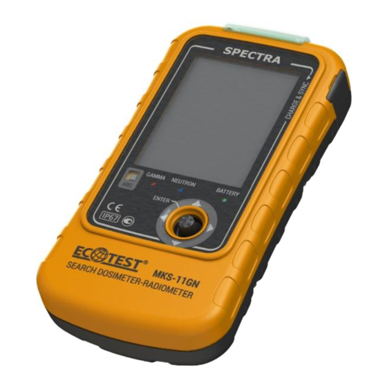
1.4 Design and principle of operation 1.4.1 General information, design overview 1.4.1.1 Appearance of the device is shown in Figure 1. Figure 1 – Appearance of the device... - Page 16 The device is structurally designed as a shape derivative of rectangular parallelepiped with flat planes being replaced with surfaces of large radii of curvature with rounded edges. The body is dustproof, waterproof, made of plastic. The device has upright working position. The ingress protection rating is –...
- Page 17 If DER exceeds 50 µSv/h by gamma channel, GDUh is automatically turned off, and the DER value is calculated from GDUl that runs continuously. The DPM consists of the nonvolatile memory, which stores the event log files, saved gamma spectra, and a library of spectra.
-
Page 18: Labeling And Sealing
1.5 Labeling and sealing 1.5.1 The upper cover and the panel of the device is inscribed with the name and a symbol of the device, the ingress protection rating and the manufacturer’s trademark. 1.5.2 The lower cover of the device contains the factory serial number and the date of manufacture. -
Page 19: Proper Use Of The Device
2 PROPER USE OF THE DEVICE 2.1 Operating limitations Operating limitations are presented in Table 2.1. Table 2.1 – Operating limitations Operating limitation Limitation parameters 1 Ambient air from –20 to 50 °С temperature Up to 100 % at 35 °С temperature, 2 Relative humidity non-condensing 3 Gamma radiation... - Page 20 2.2.3 List of possible troubles and troubleshooting 2.2.3.1 The list of possible troubles and troubleshooting is presented in Table 2.2. Please record the possible troubles in the table of Annex A of the Operating Manual. Table 2.2 – Possible troubles and troubleshooting Trouble, its manifestation Probable trouble Troubles-...
-
Page 21: Use Of The Device
HS failed - failure of a high-sensitivity gamma radiation detector; LS failed - failure of low-sensitivity gamma radiation detector; TS failed - temperature sensor malfunction; NS failed - neutron detector failure; In the event of any of these faults, please return the device to the manufacturer for repair. - Page 22 2.3.1.6 In the event of contamination, the device is subject to decontamination by wiping its surfaces by a gauze swab moistened with a standard decontaminating agent. 2.3.1.7 Disposal of the device should be performed according to DSTU 4462.3.01:2006, DSTU 4462.3.02:2006, and Laws of Ukraine On Environmental Protection and On Waste.
- Page 23 2.3.2.3.1 Vibration and sound signals: "Quantum", a sequence of short beeps that indicate the intensity of registered gamma quanta or neutrons. Signal frequency is proportional to the count rate of gamma quanta or neutrons. Signal "Quantum" can be enabled or disabled only when the intensity histograms of gamma and neutron channels are displayed.
- Page 24 icon that is totally green with no flashing "background" inside it indicates that the calibration is completed. Note 1. Calibration by the level of gamma background is done automatically when switching the device on, exiting the identification mode, or as required by the user. Calculation of the search sigma threshold level of the alarm is performed regardless of the operating mode of the device.
- Page 25 When you connect the device via the USB-cable to the PC (if the device was switched on), the device automatically switches off and goes to the charging mode. Run the "Spectra Reader" software and enter the correct password to switch to the mode of data communication with the PC.
- Page 26 2.3.3.1 Switching the device on and entering the measurement mode To switch the device on, hold down the central joystick button for at least 3 seconds. A backlit graphical color display (hereinafter - the display) indicates that the device is on, and then it will show information about the device and the producer’s trademark (Fig.
- Page 27 Operation in the "Administrator" mode is different in that you can change those device settings that directly affect its operation (thresholds levels of alarm triggering by gamma and neutron channels coupled with the time and date of the device). To enter the "Administrator"...
- Page 28 2.3.3.3 The mode of DER measurement and display by gamma and neutron channels As you log in as a "User" or as an "Administrator", the device enters the mode of DER measurement and indication by gamma and neutron channels. The "DER" label in the upper left corner of the display indicates that the device is in this mode.
- Page 29 neutrons count rate is surpassed, the icons alternately appear in the relevant area, whereas actuation of both alarms makes alternately appear. Light, sound, and/or vibration alarm also turns on according to the device’s settings. On exceeding of the set threshold level of alarm triggering by the safety level, the icon appears, and light, sound, and/or vibration alarm also turns on according to the device’s settings.
- Page 30 The display of random DER counts or intensity count rate by the neutron channel for less than 24 seconds without actuation of the neutron alarm threshold is very common and should not be considered. 2.3.3.4 The mode that displays intensity histograms by gamma and neutron channels To go to the mode of intensity histograms by gamma and neutron channels, move the device’s joystick to the left or to the right...
- Page 31 In the upper left corner of the histograms, there is a figure that demonstrates the current dimension of the histogram, and each point within its field on the vertical axis indicates the 1/10 of this value (Fig. 7). Note. In the absence of a neutron radiation source in the environment, the intensity histogram of neutron radiation will not be seen on the display since the common background radiation has no neutron component.
- Page 32 pulse count rate is followed by sound, the icon – that sound is absent. Short presses of the central joystick button, when sound of pulse count rate is enabled, initiates recalibration of the sounding rate relative to the current pulse count rate, which make it possible to distinguish sounds when the device approaches a radiation source and switch sound from the mode of continuous signal to a distinct periodic one.
- Page 33 The accumulated dose and the time since when the device is switched on appear on the display. If sigma threshold for gamma radiation exceeds the set level of alarm triggering, the icons alternately appear in the corresponding area. If the threshold level of alarm triggering by neutrons count rate is exceeded, the icons appear in sequence in that area.
- Page 34 (Fig. 9): • Start identification: launches the identification process • Saved spectra: allows you to view the saved spectra. To go to the desired menu item, move the device’s joystick up or down until this option is highlighted with a cursor, and then press the central joystick button to confirm that you want to go to this item.
- Page 35 2.3.3.6.1 Identification of radionuclides The device contains a library of 32 radionuclides capacity. The library can be expanded up to 128 radionuclides via “Spectra Reader” software in a separate order. Imporatnt! Before starting the identification process, make sure that the gamma radiation DER from the radionuclide under study is greater than 0.3 μSv/h, otherwise the identification process will not...
- Page 36 To start the process of identification of radionuclides, go to "Start identification", and the screen below will open (Fig. 11): Figure 11 – Radionuclides identification process This screen shows the following data: At the top of the screen, there is the ambient dose equivalent rate;...
- Page 37 2.3.3.6.2 Completing the identification process After automatic or forced stop of the identification process the following screen appears (Fig 12): Figure 12 – Identification process completion This screen shows the following data: At the top of the screen, there is the ambient dose equivalent rate;...
- Page 38 To read the gamma spectra and delete them from the device’s memory, use the "Spectra Reader" software (2.3.3.7).
- Page 39 2.3.3.6.3 Expert Mode Expert Mode allows you to analyze an accumulated spectrum in detail and view the peaks found. To go to the Expert Mode, select "Expert Mode" during identification of radionuclides. The Expert Mode screen appears (Fig. 13): Figure 13 – Expert mode This screen displays the following: At the top of the screen you can the ambient dose equivalent rate;...
- Page 40 – returns to a standard spectrum scale, – scales the spectrum up or down. Moving the device’s joystick to the right increases scaling by the energy, to the left - decreases. Moving the joystick up increases scaling by amplitude gamma spectrum, down - decreases (Fig. 14): Figure 14 –...
- Page 41 Figure 15 – Spectrum move mode – allows you to view a particular spectrum channel. As you move the device’s joystick to the right moves the cursor five pixels of the display rightwards, to the left - five display pixels leftwards. Move the device’s joystick up to move the cursor one display pixel rightwards, down - one display pixel leftwards (Fig.
- Page 42 To stop the identification process, wait for the auto completion or select "Stop ID". 2.3.3.6.4 Viewing saved spectra You can view spectra saved in the device’s memory by switching to the "Saved spectra" item in the mode of radionuclides identification. The following window opens:...
- Page 43 Figure 18 – Viewing the list of saved spectra This window contains the list of spectra saved in the device’s memory. If the number of saved spectra is too big for simultaneous display in the field, move the device’s joystick down as many times as required to go down the list and view them (Fig.
- Page 44 Managing viewing and the way of data display is identical to operation in expert mode in the process of radionuclides identification. 2.3.3.7 The mode of the device setup To switch to the setup mode, move the device’s joystick to the left or to the right (depending on the current operating mode of the device).
- Page 45 • Location - setting the device's navigation receiver, • Measurements – setting thresholds of the alarm triggering and measurements saving, • Time&Date – setting time and date, • Device Info – information about the device and the manufacturer, • Device off – switching off the device. To switch to the required item of settings, move the device’s joystick up or down until this item becomes highlighted by the cursor, then press the central joystick button to confirm switching...
- Page 46 Each item of the setup menu contains icons , (but for "Device Info" item) and responsible for settings saving and returning to the previous menu without saving settings respectively. To select the desired icon, move the device’s joystick up or down until this icon becomes highlighted with green cursor (for example, ), then press the central joystick button to confirm.
- Page 47 • Backlight timeout - makes it possible to set the following display backlight time: 15 s, 30 s, 60 s, 120 s, 300 s or continuous backlight. 2.3.3.7.2 Sound “Sound” item contains the following settings (Fig. 22): Figure 22 – Setting sound signals •...
- Page 48 2.3.3.7.3 Vibration “Vibration” item contains the following settings (Fig. 23): Figure 23 – Setting vibration signals • ON Vibro – makes it possible to enable or disable vibration signals when switching the device on and off; • Key Vibro – makes it possible to enable or disable vibration during manipulations with the device controls;...
- Page 49 2.3.3.7.4 Light “Light” item contains the following settings (Fig. 24): Figure 24 – Setting light signals • On Light – makes it possible to enable or disable light signals when switching the device on and off; • Alarm Light– makes it possible to enable or disable the light alarm triggered by exceeding the threshold level of radiation;...
- Page 50 2.3.3.7.5 Language “Language” item makes it possible to change the data display language on the device display (Fig. 25): Figure 25 – Setting the language 2.3.3.7.6 Location “Location” item contains the following settings (Fig. 26): Figure 26 – Setting the parameters of navigation receiver •...
- Page 51 • Location info - makes it possible to switch to viewing the current data of navigation receiver, namely, time, date, coordinates, number of satellites currently found by the device (SIU), as well as information on whether these coordinates are reliable (Fig. 27). Figure 27 –...
- Page 52 To read and clear the events from the device’s memory use the "Spectra Reader" software.
- Page 53 2.3.3.7.8 Time and Date “Time and Date” item contains the following settings (Fig. 29): Figure 29 – Setting time and date parameters • Current time – allows setting the current time; • Current date – allows setting the current date. IMPORTANT! The option to configure "Current time"...
- Page 54 2.3.3.7.9 About the device "About the device" item contains information about the device model, version of its proprietary software, serial number, and information about the device’s manufacturer (Fig. 30). Figure 30 – About the device This item also contains the "Change password" subitem that allows you to change the password to enter in the "Administrator"...
- Page 55 • Enter password - enter the current password in this field. (Default password is «0000»); • Enter new password - enter a new password in this field; • Repeat new password - reenter the new password in this field. 2.3.3.8 Energy calibration Calibration of the device by the energy allows using a calibration sample containing Th radionuclide, compensate for aging of the...
- Page 56 Figure 32 – "Energy calibration" mode 2.3.3.8.2 Wait until the calibration is completed. The following messages may appear on the display of the device: "Calibration successful" – which means that the device correctly identified all the given photopeaks of the calibration sample and successfully performed compensation of the measuring path (Fig.
- Page 57 - "Calibration failed" – which means that the device could not correctly detect the photopeaks of the calibration sample or cannot perform compensation of the measuring path (Fig. 34). Please, contact the manufacturer in this case. Figure 34 – "Calibration failed" - "Calibration failed High DER"...
- Page 58 IMPORTANT! Smooth operation of "Spectra Reader" SW requires installation of at least OS Windows 7 on the PC. To install the driver and "Spectra Reader" SW you might need to login in the OS of your PC as the "Administrator". In case of complications, please contact your system administrator who supports your PC.
- Page 59 "ST Microelectronics Virtual COM Port". COM-port (COM__) number specified opposite the device is used to select the login window to "Spectra Reader" SW in the "COM-port" field. If you connect the device to the same USB-port of the PC each time, the number of its COM-port does not change.
- Page 60 2.3.3.9.3 Events reading After starting the "Spectra Reader" SW, the "Events" tab opens, which allows managing the events saved in the device’s memory. In the upper left corner of the "Events" tab a serial number of the connected device is highlighted in the format "Ser.number ХХХХХХХХ", where ХХХХХХХХ...
- Page 61 2.3.3.9.4 Working with the readout events After successful reading of the events from the device, they are displayed in the "List of Events" field of the "Events" tab (Fig. 38). Figure 38 – Readout events Select the required event in the "List of events" field. The information it contains is displayed rightwards below the "Events Filter"...
- Page 62 IMPORTANT! If the events were not saved on the PC’s hard drive (or removable disk drive), they are not subject to recovery after removal from the device’s memory. The upper right corner of the "Events" tab contains the following buttons of the events control: - saving all events to the PC’s hard drive in the .dat format (including those that are not displayed according to filters);...
- Page 63 • Cursor - allows channel-by-channel preview of the selected spectra, • Filter by date - you can select a date of spectra saving in this field to be displayed in the list after reading from the device.
- Page 64 2.3.3.9.6 Working with read spectra After successfully reading spectra from the device, they will appear in the in the "Spectra List" field of "Spectra" tab (Fig. 41). Figure 41 - Image of spectra Select the necessary entry in the "Spectra list" field by the date and time of creation.
- Page 65 If you need to sort the loaded spectra, you may set the time interval in the field of filtering by date to display spectra, which creation date falls within this interval. You should check the box opposite fields "from"...
- Page 66 2.3.3.9.7 Library of nuclides "Library of nuclides" tab allows you to manage the library of radionuclides saved in the device’s memory (Fig. 42). Figure 42 – "Library of nuclides" tab There is a field of radionuclide libraries viewing downloaded from a file in the left part of this tab. The right part of this tab contains the following buttons: •...
- Page 67 2.3.3.9.8 Managing libraries of radionuclides To download a new library in the device first read it into the "Spectra Reader" SW from a file in .bn format. Library file is provided by the device manufacturer in a separate order. Click "Read library from file" button to open the following window (Fig.43):...
- Page 68 Choose the directory where the file with the library is located and click "Open". You will see the following window (Fig.44): Figure 44 – Library of nuclides read from file A list of radionuclides contained in the read file appears in the field of viewing libraries of radionuclides in the following format: ITEМ...
- Page 69 Important! Previous library must be cleared from the device’s memory before loading a new one; otherwise, an appropriate warning appears when you try to download. 2.3.3.9.9 Settings "Settings" tab allows configuring the device operation parameters and change its PIN code (Fig. 45). Figure 45 –...
- Page 70 • Software update - allows you to enter the firmware update mode. 2.3.3.9.10 PIN code change To change the PIN code of access to "Spectra Reader" SW and login as the "Administrator" in the device, click on the "Change PIN code" button on the right side of the "Settings" tab.
- Page 71 Figure 46 – PIN code change 2.3.3.9.11 Software update IMPORTANT! Ensure uninterrupted power to your PC throughout the software update process. Click the "Software Update" button to open the following window (Fig. 47):...
- Page 72 Figure 47 – Confirmation of the firmware change of the device After confirmation the following window will appear (Fig. 48): Figure 48 – Switch the device in the boot mode. To switch the device to the boot mode, you need to press and hold the "OK"...
- Page 73 Figure 49 – The device in the boot mode After switching the device to the boot mode, click the "OK" button in the program window (Fig. 48). Select the directory where the firmware file in .bin format is located (Fig. 50). Figure 50 –...
- Page 74 As soon as you choose the correct file, the process of firmware of the device will begin displaying the update progress (Fig. 51) Figure 51 - Firmware update progress IMPORTANT! Do not remove the USB cable until the boot process is complete (Fig. 52) Figure 52 - Software update completed.
- Page 75 2.3.3.7.12 Completion of operation in the mode of data communication with PC After completion of operation and exiting the "Spectra Reader" SW, the device automatically turns off and switches to the charging mode until it is disconnected from the PC.
-
Page 76: Technical Maintenance
3 TECHNICAL MAINTENANCE 3.1 Technical maintenance of the device 3.1.1 General guidelines The list of operations during technical maintenance (hereinafter – the TM) of the device, the order of priority and features at different stages of the device use is shown in Table 3.1. Table 3.1 - List of operations during technical maintenance Type of technical maintenance during... - Page 77 3.1.2 Safety measures TM safety measures fully comply with safety measures presented in OM 2.3.1. 3.1.3 TM procedure of the device 3.1.3.1 External examination Examination of the device should be performed in the following order: а) check the condition of the device’s surfaces, the integrity of seals, absence of scratches, traces of corrosion, and surface damage of coating;...
-
Page 78: Verification Of The Device
3.2 Verification of the device 3.2.1 Devices should be verified during operation (periodic verification at least once a year) and after repair according to verification methods, which are determined by regulations of the central executive body, which ensures the formation of state policy in the field of metrology and metrological activities, or by national standards. - Page 79 3.2.3 Verification operations During verification the operations presented in Table 3.2 should be performed. Table 3.2 - Verification operations Verification Operation technique No. 1 External examination 3.2.4.1 2 Testing 3.2.4.2 3 Calculation of the main relative 3.2.4.3 permissible error limit during gamma radiation DER measurement 4 Checking the ability to identify the 3.2.4.4...
- Page 80 Table 3.3 Regulatory documents or technical Name specifications УПГД-3Б Ambient dose equivalent rate of gamma standard radiation in the range from 0.1 to µSv/h. equipment Energy range from 59 kеV to 1.25 MeV. Main relative permissible error limit of gamma radiation DER and DE – 4 % with confidence probability of 0.95 УКПН-1М...
- Page 81 3.2.5 Verification conditions 3.2.5.1 Verification should be carried out under the following conditions: - ambient air temperature within (20±5) °С; - relative air humidity within (65±15) %; - atmospheric pressure from 84 kPa to 106.7 kPa; - natural gamma radiation background should not exceed 0.25 µSv/h;...
- Page 82 3.2.6.2.3 Place the device in the УКПН-1М carriage holder so that the mechanical center of neutron beam coincides with the one of the device’s neutron detector. Place the УКПН-1М carriage holder with the device in the position, where neutron radiation from Pu-Be ensures pulse count rate from the neutron detector within a 10 –...
- Page 83 (3.1) 3.2.6.3.2 Place the УПГД-3Б carriage holder with the device in the position, where gamma radiation DER from the Cs source is =(10.0 0.1) µSv/h. After the device has been exposed to H radiation, wait for 5 s and proceed to take five measurements of gamma radiation DER with a 10 s interval.
- Page 84 S - a relative root-mean-square deviation of measurement result calculated by the formula: − − (3.4) 3.2.6.3.3.2 Calculate the limit of residual systematic error of measurement results by the formula ...
- Page 85 3.2.6.3.4 Perform operations 3.2.6.3.2, 3.2.6.3.3 for gamma = (8.0 0.8) mSv/h. Set the safety H radiation DER threshold equal to 6 mSv/h. Make measurements in 60 s after the beginning of irradiation at 60 s interval. 3.2.6.3.5 The device is acknowledged to have passed the verification test if the main relative permissible error at measurement for each level of gamma radiation DER does not H ...
- Page 86 3.2.6.5 Determination of the main relative permissible error limit of gamma radiation DE measurement by the built-in GMC. 3.2.6.5.1 To determine the main relative permissible error limit of gamma radiation DE measurement by the built-in GMC, do the following: 3.2.6.5.2 Switch on the device and log in in the “Administrator”...
- Page 87 (3.10) where t - the limit of the main relative permissible error of the measurement of the gamma DE exposure time, which must be not exceed 5%, is calculated by the formula: ...
-
Page 88: Certificate Of Acceptance
4 CERTIFICATE OF ACCEPTANCE The MKS-11_____ “SPECTRA” Search Dosimeter-Radiometer ВIСТ.412139.006_____, with _________________________ serial number is verified and accepted for use. Date of manufacture ____________________________ QCD Representative: _______________________ Stamp here (signature) 5 PACKING CERTIFICATE The MKS-11_____ “SPECTRA” Search Dosimeter-Radiometer ВIСТ.412139.006_____ with ___________________________ serial number is packed by the PE “SPPE “Sparing-Vist Center”... -
Page 89: Warranty
6 WARRANTY 6.1 The manufacturer guarantees the conformity of the device with the technical requirements if the customer observes the guidelines on its use, shipping and storage presented in the OM ВIСТ.412139.006-02 НЕ. 6.2 The warranty period of use of the device shall terminate and be of no further effect in 24 months after the date of putting it into operation or after the warranty period of storage terminates. -
Page 90: Repair
7 REPAIR 7.1 In case of failure or troubles during the warranty period of the device, the user should contact the supplier in his/her country. Warranty and post-warranty repair should be done only by the manufacturer at the following address: PE “SPPE “Sparing-Vist Center”... -
Page 91: Storage
8 STORAGE 8.1 The devices should be stored in the packing box under conditions 1 (Л) according to GOST 15150-69 standard in heated and ventilated storehouses with air-conditioning at the ambient air о С and relative humidity up to 80 % at temperature from +5 to +40 о... -
Page 92: Shipping
9 SHIPPING 9.1 Packed devices may be shipped by any kinds of closed transport vehicles under the conditions 4 (Ж2) (with temperature limitations in the range of – 25 о С to +50 о С) according to GOST 15150-69 and rules and standards effective for each means of transport. -
Page 93: Annex А
ANNEX А TROUBLE RECORD DURING USE... -
Page 94: Annex B
ANNEX B PERIODIC VERIFICATION OF MAIN SPECIFICATIONS Verified specification Date of measurement Year of 20 Year of 20 Year of 20 Standardized Name value Main ±(15+1/ H relative permissible H where - is error during a measured value gamma radiation of gamma... -
Page 95: Annex C
ANNEX C INFORMATION ABOUT DEVICE REPAIR... -
Page 96: Annex D
ANNEX D STORAGE Date Position, name and signature of Storage conditions of placing in of removing the responsible storage from storage person... -
Page 97: Annex E
ANNEX E PUTTING IN PROLONGED STORAGE AND REMOVAL FROM STORAGE Date of Name of the Date, position removal enterprise in charge Storage and signature of from of putting or method the responsible prolonged removing from person storage prolonged storage... -
Page 98: Annex F
ANNEX F VERIFICATION AND INSPECTION RESULTS Position, name Verification and signature of Verification or Date or inspection the person inspection result type responsible for inspection...
Need help?
Do you have a question about the MKS-11 and is the answer not in the manual?
Questions and answers