Advertisement
ISL68134-31P-EV1Z
Evaluation Board Quick Start User Guide
Description
The ISL68134-31P-EV1Z evaluation board provides users a
method of evaluating the
ISL68134
Included on the board is a high-performance transient load
generator capable of replicating the type of high di/dt loads
typical of today's high current ASICs.
The ISL68134 is combined with the ISL99227 Smart Power
Stage (SPS) to provide a highly efficient power solution
capable of delivering up to 135A.
While the user may opt to evaluate the solution based on the
Intersil default configuration, custom configurations are easily
created using PowerNavigator™.
Specifications
This board has been configured and optimized for the following
operating conditions:
• 0.6V to 1.8V output range. Up to 3.05V with BOM change
• 3+1 phase: 135A + 30A
• Input range from 5V to 16V
UG095 Rev 0.00
October 4, 2016
digital multiphase device.
USER'S MANUAL
Key Features
• 0.5% V
regulation accuracy
OUT
• PMBus interface, AVSBus interface
• 3% I
telemetry accuracy
OUT
• Onboard transient load to facilitate testing
• ATX or bench supply connections for input sources
Related Literature
• For a full list of related documents please visit our website
-
ISL68134
product page
Ordering Information
PART NUMBER
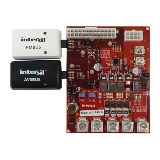
ISL68134-31P-EV1Z ISL68134 evaluation board, 3+1 dual output
(EVB, PMBus adapter, AVSBus adapter, two USB
cables)
UG095
Rev 0.00
October 4, 2016
DESCRIPTION
Page 1 of 8
Advertisement
Table of Contents

Subscribe to Our Youtube Channel
Related Manuals for Renesas ISL68134-31P-EV1Z


Summary of Contents for Renesas ISL68134-31P-EV1Z
- Page 1 UG095 Evaluation Board Quick Start User Guide Rev 0.00 October 4, 2016 Description Key Features The ISL68134-31P-EV1Z evaluation board provides users a • 0.5% V regulation accuracy method of evaluating the ISL68134 digital multiphase device. • PMBus interface, AVSBus interface Included on the board is a high-performance transient load •...
- Page 2 PHASE FAULT# TWARN ISL99227 PVCC TMON PWM3 IMON 0.1µF 2x22µF CSRTN3 REFIN BOOT 0.1µF 470pF PHASE SALRT FAULT# TMON1 VOUT1 470pF CONFIG RGND1 VSEN 1 FIGURE 1. ISL68134-31P-EV1Z BLOCK DIAGRAM UG095 Rev 0.00 Page 2 of 8 October 4, 2016...
- Page 3 ISL68134-31P-EV1Z FIGURE 2. CONNECTIONS UG095 Rev 0.00 Page 3 of 8 October 4, 2016...
-
Page 4: Functional Description
ISL68134-31P-EV1Z Functional Description Transient Load The ISL68134-31P-EV1Z provides a convenient method to The transient load on this board is attached to VOUT1 and is evaluate the performance of Intersil’s family of digital capable of >100A and >200A/µs for output voltage down to 1V. -
Page 5: Default Configuration Settings
ATX_ON switch. 6. Launch PowerNavigator™. Device should be discovered by PowerNavigator™. Select “Open Existing Project” (Figure FIGURE 5. LAUNCH PowerNavigator™ 7. Select ISL68134-31P-EV1Z and then click “START”. FIGURE 7. POWER MAP 10. Begin Testing. UG095 Rev 0.00 Page 5 of 8... - Page 6 ISL68134-31P-EV1Z ISL68134-31P-EV1Z Evaluation Board AVSBUS PMBUS CONNECTOR CONNECTOR TRANSIENT LOAD VOUT1 INPUT VOUT0 12V BENCH INDUCTORS SUPPLY INPUT AND SPS FIGURE 8. TOP SIDE TRANSIENT LOAD ISL68134-31P-EV1Z OUTPUT CAPACITANCE FIGURE 9. BOTTOM SIDE UG095 Rev 0.00 Page 6 of 8...
-
Page 7: Typical Performance Curves
ISL68134-31P-EV1Z Typical Performance Curves Unless otherwise noted: V = 12V, f = 500kHz, APD disabled, T = +25°C ± <3% DEVIATION C1 20mV/DIV TEST CONDITIONS: = 12V = 1V = ~4800µF = 500kHz 50A STEP AT 100A/µs 0.8VOUT 1VOUT C2 200mV/DIV 1.2VOUT... - Page 8 10. It is the responsibility of the buyer or distributor of Renesas Electronics products, or any other party who distributes, disposes of, or otherwise sells or transfers the product to a third party, to notify such third party in advance of the contents and conditions set forth in this document.
Need help?
Do you have a question about the ISL68134-31P-EV1Z and is the answer not in the manual?
Questions and answers